XCHARGE C6EU User manual

C6EU SERIES
Installation and Operation
Manual
ENGLISH


Copyright | C6EU SERIES Installation and Operation Manual, Version 1.6 1
Copyright
XCHARGE reserves all rights to this document and to the information and topics contained
in it. This also applies to any possible claims to copyright or patents. Forwarding and/or
the duplicating of this document without the express permission of XCHARGE is forbidden.
Changelog
Date Changed by Version Changes
2020-02-20 Alex Sheng 0.1
2020-04-06 Benjamin Tange 0.9 Minor changes and formatting
2020-06-30 Benjamin Tange 0.91 Minor changes, corrections in tech data
2020-07-10 Alex Sheng 1.0 Change the rendered picture
compatible with credit card payment.
Corrections in tech data
2020-09-22 Heather Xue 1.1 Installation instruction with stainless
steel frame (Section 4.3.2)
2021-01-22 Alex Sheng 1.2 Minor changes in 3.8 curve
2021-02-07 Ethan Sun 1.3 Edit Fault diagnosis and error code
2021-02-07 Alex Sheng 1.4 Minor changes in stainless steel frame
(Section 4.3.2)
2021-02-09 Stephan
Nusseck
1.5 Updated optional 250 A CCS cable and
minor corrections in tech data
2022-05-24 Alex Zhang 1.6 Updated optional 300 A CCS cable and
200kW power output

2Copyright | C6EU SERIES Installation and Operation Manual, Version 1.6
Catalogue
Changelog ............................................................................................................................. 1
1. Introduction and Safety Information ........................................................................... 4
1.1 Preface ....................................................................................................................... 4
1.2 Proper Usage ............................................................................................................. 4
1.3 Intended document user........................................................................................... 4
1.4 Important safety instructions ................................................................................... 5
1.5 Important signs ......................................................................................................... 6
2. Product Description ...................................................................................................... 8
2.1 System overview........................................................................................................ 8
2.2 Charging connector system .................................................................................... 10
3. Technical Data............................................................................................................. 11
3.1 Nameplate ............................................................................................................... 11
3.2 Electrical data.......................................................................................................... 11
3.3 Mechanical data ...................................................................................................... 12
3.4 Environmental data................................................................................................. 13
3.5 Technical Standards................................................................................................ 13
3.6 Electrical Diagram ................................................................................................... 14
3.7 Function Structure of C6EU..................................................................................... 15
3.8 C6EU Power Curve................................................................................................... 16
4. Installation................................................................................................................... 18
4.1 Required space for placing and maintaining ......................................................... 18
4.2 Installation warnings............................................................................................... 19
4.3 Construction Foundation........................................................................................ 19
4.3.1 Concrete Foundation........................................................................................... 19
4.4 Power supply and power cable............................................................................... 21
4.5 Packaging and Unpacking....................................................................................... 22
4.5.1 Packaging............................................................................................................. 22
4.5.2 Unpacking............................................................................................................ 23
4.6 Positioning and wiring ............................................................................................ 23
4.7Verification of measurement values....................................................................... 26

Copyright | C6EU SERIES Installation and Operation Manual, Version 1.6 3
5. Commissioning and operation ................................................................................... 27
5.1 Power up.................................................................................................................. 27
5.2 Display and usage.................................................................................................... 27
5.2.1 Display and usage................................................................................................ 27
5.2.2Control Panel ....................................................................................................... 28
5.3 Charging process ..................................................................................................... 28
5.4 Indicator lights......................................................................................................... 31
6. Fault diagnosis ............................................................................................................ 31
7. Maintenance................................................................................................................ 34
7.1 Cleaning of the cabinet ........................................................................................... 34
7.2 Anti-dust net replacement ...................................................................................... 34
8. Contact Information.................................................................................................... 36

4Copyright | C6EU SERIES Installation and Operation Manual, Version 1.6
1. Introduction and Safety Information
1.1 Preface
This manual describes the features and functions as well as installation, operation and
maintenance of the XCHARGE C6EU hyper charger.
Due to the high technical modularity and the different customer requirements there are
various variants, which differ in the maximum output power, the installed charging cables
and connectors as well as display. The components shown in this guide are all example
graphics. The illustrations and explanations refer to a typical version of the device. The
design of your device may differ from description in manual. Please read this document
carefully and adapt to the realistic.
1.2 Proper Usage
This product is a high-power EV supply equipment (EVSE) for recharging electric vehicles
(EVs) using the fixed cable and CCS Combo 2 (CCS2) and/or CHAdeMO connectors.
When any loss or damage occurs due to improper use or unauthorized modification of the
product, XCHARGE SHALL NOT be liable for the product, the purchaser or third parties. The
same is also valid if the maintenance provided by XCHARGE is not strictly complied.
The installation requires a planning with care and can only be carried out by qualified
personnel (electricians).
1.3 Intended document user
This document is intended for:
•Customers who purchased a C6EU, or are in the process of ordering and want to
know in more detail about installation and maintenance;
•Contractors who are responsible for site preparation and/or installation of a C6EU
Contractors who, as a qualified electrician, perform the installation,
commissioning, maintenance or repair of the XCHARGE C6EU charging station.
Requirements for the electrician:
•Knowledge of the relevant safety and accident prevention regulations;
•Knowledge of electrotechnical regulations;
•knowledge of national regulations;
•Ability to recognize risks and avoid dangers.

Copyright | C6EU SERIES Installation and Operation Manual, Version 1.6 5
1.4 Important safety instructions
WARNING
(Safety instructions on a risk with medium risk level! Failure to comply can result in death
or serious injury)
1. Please confirm the voltage and current level before installation.
2. The entire installation process needs to be conducted by qualified personnel.
3. Please do not operate in the cloudy, rainy weather or similar conditions may causing
possible leakage.
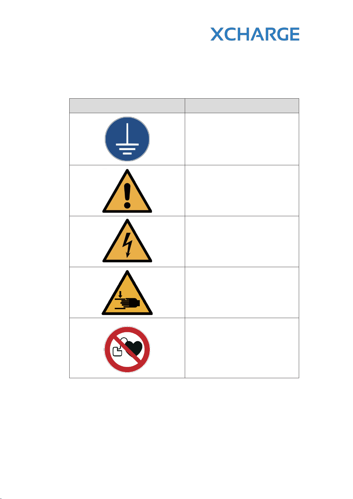
4. DC charging station must be earthed properly.
5. Do not install or use the charging station closed to flammable, explosive materials or
steam.
6. Without qualified personnel, do not try to open, disassemble, or modify the charging
station.
7. The use of charging stations may affect or damage some medical or implantable
electronic equipment, such as cardiac defibrillators, pacemakers, etc.
ATTENTION
(Safety instructions on a risk with a low degree of risk! Non-compliance can lead to minor to
moderate injury)
1. Please use this product in cool and ventilated environment.
2. Before installing or cleaning the charging station, power supply must be shut down.
3. Please use the charging station within the parameters range as specifications
addressed.
4. Do not use the charging station with non-charging purpose or others not supporting
CCS2 or CHAdeMO charging standard vehicles.
5. If defectives are found, such as cracking, wear, inoperable parts or other damage, stop
using the charging station immediately and call the customer service.
6. Do not use the charging station when exposing to heavy rain, thunder, heavy snow or
other severe weather conditions may causing damage to station and personal property.
7. Please be careful when transporting the charging station. Avoid strong external shocks.
Do not drag, twist or step on the charging station to prevent damage to any parts. At any
time, avoid and prevent damage to the charging station from moisture, liquids and
foreign objects. Do not use if water is present or station is suspected of being damaged
or corrosive. Do not touch the charging station, charging cable and charging connector
with wires, tools, or other sharp objects.
8. If EV is covered by external protection hood, do not use charging station.
9. Do not start and drive your EV when socket is still connected. The user is responsible for
the damage to the EV and charging station caused by former addressed case.

6Copyright | C6EU SERIES Installation and Operation Manual, Version 1.6
1.5 Important signs
According to ISO7010 and other similar standards, the operating, warning and prohibition
signs below are stuck to the C6EU and are also used in the manual.
Warning Signs Description
Earthing
Connect an earth terminal to the ground
General Warning Sign
Identify a hazard which could result in
damage to the operator, machinery,
other equipment and/or pollution
Electricity Hazard
Warning of electrical voltage
Crushing of Hands
Touching the device may result in hand
injury
No access for people with active
implanted cardiac devices
Table 1.5.1 Warning Signs

Copyright | C6EU SERIES Installation and Operation Manual, Version 1.6 7
These signs below are also used on the nameplate of C6EU.
Signs Description
Note Documentation
Note all documentation, which are
supplied with the product
WEEE Symbol
Do not dispose of the product with
domestic waste. Please follow the valid
disposal regulations in the installation
site for electronic waste.
CE Mark
Table 1.5.2 Other signs on the nameplate

8Copyright | C6EU SERIES Installation and Operation Manual, Version 1.6
2. Product Description
2.1 System overview
Table 2.1.1 Housing and exterior elements
AHD/Touch screen, diameter 22.5 cm
(HMI) ELED Indicator
BEmergency button FCharging connector
CControl panel with RFID/Credit card
reader GCable management
system
DAir inlet HAir outlet
E
F
G
H

Copyright | C6EU SERIES Installation and Operation Manual, Version 1.6 9
This manual is valid for all the C6EU Versions, which are shown below in Table 2.1.2. and
Table 2.1.3.
Type Max. output
power
Max. output
DC current
Power
module
(30kW)
CCS Combo 2
connector
CHAdeMO
connector
C6EU-060-JC 60kW 200A 2200/250Ax1 125Ax1
C6EU-120-JC 120kW 400A 4200/250Ax1 125Ax1
C6EU-120-CC 120kW 400A 4200/250Ax2 N/A
C6EU-150-JC 150kW 500A 5200/250Ax1 125Ax1
C6EU-150-CC 150kW 500A 5200/250Ax2 N/A
Table 2.1.2 Type of C6EU in 30kW steps
Type
Max.
output
power
Max.
output DC
current
Power
module
(40kW)
CCS Combo 2
connector
CHAdeMO
connector
C6EU-080-CC 80kW 250A 2200/250/300Ax2 N/A
C6EU-120-CC 120kW 500A 3200/250/300Ax2 N/A
C6EU-160-CC 160kW 500A 4200/250/300Ax2 N/A
C6EU-200-CC 200kW 500A 5200/250/300Ax2 N/A
Table 2.1.3 Type of C6EU in 40kW steps
Notes:
•All the double-connector versions work in the smart mode: the whole output
power of charger is distributed over two connectors averagely or by one
connector at the proper charging voltage level. For each side the output current
can also be limited as requested;
•You can recognize the different types of C6EU through the first eight letters in its
SN number, for example in SN number “C6E12JC20IQBHUVPW” the type is C6EU-
120, up to 120kW output with CCS and CHAdeMO connector;
•Touch or non-touch screen is optional for all these kinds of C6EU.
Figure 2.1 Rendering of C6EU

10 Copyright | C6EU SERIES Installation and Operation Manual, Version 1.6
2.2 Charging connector system
CHAdeMO CCS Combo 2 (CCS2)
Table 2.2 Structure sketch of charging connectors: CHAdeMO and CCS 2

Copyright | C6EU SERIES Installation and Operation Manual, Version 1.6 11
3. Technical Data
3.1 Nameplate
Figure 3.1.1 Nameplate template
Nameplate contains all the necessary information includes:
•Product type and serial number;
•Input power and wiring parameter;
•DC rated output voltage, current and power;
•Manufacturing date;
•Markings.
3.2 Electrical data
Input
Input voltage range 3 phase 400 VAC ± 10% 50 Hz
Power factor > 99% at nominal output power
Efficiency 95% at nominal output power
DC output CCS2 (C)
Maximum output power 200 kW
Output voltage range 200 – 1000 VDC (Combo-2)
Maximum output current 200 ADC or 250 ADC or 300 ADC continuously (CCS 2)
THD < 5 % (50-100% of rated output power)

12 Copyright | C6EU SERIES Installation and Operation Manual, Version 1.6
DC output CHAdeMO (J)
Maximum output power 60 kW
Output voltage range 50 – 500 VDC (CHAdeMO)
Maximum output current 125 ADC (CHAdeMO)
THD < 5 % (50 -100% of rated output power)
General
DC connection standard IEC 61851-1:2011, IEC 61851-23:2014, IEC 61851-24:2014,
IEC 62196-3:2014, ISO 15118, DIN 70121-2014, CHAdeMO 2.0
DC cable length 3.2m; optional 5 / 7 / 10 m (with cable management system)
DC connector type CCS 2 / CHAdeMO
RFID system ISO 14443 A&B / ISO 15693 / ISO18092 / ECMA-340
Table 3.2.1 Electrical data of C6EU
3.3 Mechanical data
Mechanical Data
Dimensions (H x W x D)
1750 mm x 615 mm x 740 mm
1981 mm x 764 mm x 872 mm (with cable management
system)
Weight 325 (60 kW) - 395 kg (200 kW)
Volume 0.75m3
Dimensions including packaging 2100 mm x 850 mm x 900 mm
Weight including packaging 375 (60 kW) - 450 kg (200 kW)
Weight concrete foundation Min. 450 kg
Mechanical impact protection IK10
Table 3.3.1 Mechanical data of C6EU

Copyright | C6EU SERIES Installation and Operation Manual, Version 1.6 13
3.4 Environmental data
Environmental Data
Ground load bearing At least 450 kg
Ingression protection IP 54
Temperature range – Operation - 25 °C to + 50 °C,
- 40 °C to 55 °C (optional, with additional heat pump)
Temperature range – De-rating + 50 °C to +70 °C
Temperature range – Storage - 40 °C to + 80 °C
Operating Relative Humidity 5 % to 95 %, no condensing on the surface
Storage Relative Humidity 95 %, no condensing on the surface
Humidity Up to 95% no condensation on the surface
Operational noise level <65 dB in rated output power
Atmospheric Pressure 79 KPa - 106 KPa
Altitude 2000 m (maximum altitude without power derating)
Network GSM/WCDMA/LTE/4G/LAN
Table 3.4.1 Environmental data of C6EU
3.5 Technical Standards
The C6EU products were already approved by TÜV Rheinland according to the technical
standards below:
Technical Standards
Healthy, safety and general
requirements
EN 50385: 2017
EN 61851-1: 2011
EN 61851-23: 2014
EN 61851-24: 2014
EMC
IEC 61851-21:2018
EN 301 489-1 V2.2.0 (2017-03)
EN 301 489-3 V2.1.1 (2017-03)
EN 301 489-52 V1.1.0 (2016-11)
Radio
EN 300 330 V2.1.1 (2017-02)
EN 301 511 V12.5.1 (2017-03)
EN 301 980-1 V11.1.1 (2016-07)
EN 301 980-2 V11.1.2 (2017-08)
Table 3.5.1 Technical standard of C6EU

14 Copyright | C6EU SERIES Installation and Operation Manual, Version 1.6
3.6 Electrical Diagram
Figure 3.6.1 Electrical connection diagram
Figure 3.6.2 Fans’ control diagram
Notes:
The diagram was already approved by TÜV Rheinland according to Standard EN 61851-
23. For different types of C6EU the size of cable in the electrical connection diagram is
variable.

Copyright | C6EU SERIES Installation and Operation Manual, Version 1.6 15
3.7 Function Structure of C6EU
The Figure 3.7.1 below introduces the structure of C6EU from basic to sophisticated
functions.
Figure 3.7.1 C6EU function structure

16 Copyright | C6EU SERIES Installation and Operation Manual, Version 1.6
3.8 C6EU Power Curve
Type Power Curve (V/I)
C6EU 60kW
C6EU 120kW

Copyright | C6EU SERIES Installation and Operation Manual, Version 1.6 17
C6EU 150kW
C6EU 200kW
Table 3.8.1 C6EU power curve

18 Copyright | C6EU SERIES Installation and Operation Manual, Version 1.6
4. Installation
The product will be delivered to a warehouse by logistic company and handed over to
the customer. Normally XCHARGE is not responsible for the transport of charger to final
installation location.
4.1 Required space for placing and maintaining
The space that C6EU needs is calculated as follows:
•Vertical view: 740 mm x 615mm;
•Front and backside 0.8 meter to open the front door;
•Right and left 1.0 meter to facilitate maintenance personnel to replace the
connector cable.
The construction area is shown in the picture below.
Figure 4.1 Construction area
<- min. 0.8 m ->
<- min. 0.8 m ->
<- min. 1.0 m ->
<- min. 1.0 m ->
Other manuals for C6EU
1
This manual suits for next models
8
Table of contents
Other XCHARGE Batteries Charger manuals