XIEGU G90 User manual

XIEGU G90 CHEAT SHEET 1
This cheat sheet is intended to augment the current G90 user manual and reflects the G90’s functionality in version 1.71 of its
firmware. Significant changes with V1.71 are indicated this way. See the full V1.71 release notes at the end of this document. Note
there are a few versions of the G90 user manual so the page numbers cited here may vary depending on the manual you have.
11/1/19 KE8WO
BASIC
CONTROLS AND
BUTTONS
Power Button
Power on or off the G90 and
turn the display off
Longer press to power on the G90
Longer press to power off the G90
A short press will turn off the G90 display, but the radio continues to operate. A short press or
using any other G90 control will restore the display.
“Vol”
This rotary control sets the
audio output level from the
speaker or headphones.
Note: press this control to route the audio signal to headphones or other audio device plugged into
the headphone icon jack on the left side of the G90.
Unmarked Lower
Left Rotary Control
(‘MFC’)
This is a multifunction
control (‘MFC’) used for a
variety of purposes.
New in V1.71: Set DSP filter
center frequency and
bandwidth.
.A short press of the MFC begins a DSP filter configuration process:
With the first MFC press, a display of "Cxxx"("xxx" is the center freq) with a
vertical green line at the center allows using the MFC to set the filters center
frequency.
With the second MFC press a display of "Bxxx"("xxx" is the bandwidth) with two
vertical green lines at the sides allows using the MFC to set the filter’s bandwidth.
The last press of the MFC completes the process.
Note: A short MFC press allowed setting the squelch in the prior firmware release. This is
no longer available. See the long MFC button press Squelch level setting below.
Long press the MFC to bring up 5 choices that may be selected for basic use when the MFC is
rotated: Rotate the tuning control to select the desired choice from the five. Press the ‘CMP’ button to
save the selection. The choices are:
100 KHZ frequency step size. This allows quickly adjusting the received frequency in
100KHZ steps with the tuning control. This 100KHZ step size is fixed. This is the initial,
default setting for the MFC.
Squelch level setting. This brings up the squelch level setting where the tuning control can
select the desired squelch setting. Pressing the tuning control saves the squelch setting,
PO Level … quickly adjust the power output level with the tune control. Then press the tune
control to save the power setting.
Key Speed … use the tune control to set the CW keying speed. Press the tune control to
save the setting.
FFT Scale … use the tune control to set the base line of the FFT display up or down, Press
the MFC three times to complete this new FFT scale setting.

XIEGU G90 CHEAT SHEET 2
Right Unmarked
Rotary Control
(‘Tuning’)
This is a multifunction control
(‘Tuning’) used for a variety
of purposes.
The usual use for this control is for tuning the G90’s frequency. Pressing the control cycles the
tuning rate from 10 HZ, 100 HZ, 1 KHZ and 10 KHZ per click of the tuning knob. The tuning step
behavior is changed to from left to right.
A long press of this control has no effect.
In many other functions being used, a press of the tuning knob will complete the other function
and return the G90 to normal receiving.
Top ‘MODE’ and
‘BAND’ Buttons.
Used to select the mode or
band
Use the Mode Left or Right buttons to scroll through the six supported modes.
Use the Band Left or Right button to scroll through the ten supported amateur frequency bands.
FUNC Button
This button is used to initiate
a second function for other
buttons or controls. It also
allows detailing the G90’s
‘System Menu’.
Several new functions
added in V1.71
A short press turns on the amber LED below the button and initiates the second function by
some other button or control. These are detailed elsewhere.
A long press of this button will bring up the ‘System Menu’ to allow configuring various aspects of
the G90’s operation. See page 30 of the current User Manual. In each case use the ‘VM’ button
to step through the ten options. When making a change to one of the ten, press the ‘CMP’ button
to save the settings and exit.. Here is a brief overview of the options:
1. Handle Up / Down button .. this allows setting the function of the hand held mic’s up / down
button’s. Rotate the tuning control to select from: Freq CH +/-, Band +/-, or Volume +/-.
2. Handle F1 .. this allows assigning a function to the hand held mic’s ‘F1’ button. Rotate the
tuning control to select from PRE/ATT, SPLT (Split operation), NB (noise blanker), COMP
(speech compressor), or AGC
3. Handle F2 .. this allows assigning a function to the hand held mic’s ‘F2’ button. Rotate the
tuning control to select from the same choices as shown above for the ‘F1’button.
4. LCD BL .. rotate the tuning control to specify the desired brightness of the display from 10%
to 100%.
5. AUX IN Volume .. use the tuning control to specify the desired ACC port’s Aux In volume
from 0 to 15 (bigger is louder)
6. AUX OUT Volume use the tuning control to specify the desired ACC port’s Aux Out volume
from 0 to 15 (bigger is louder)
7. RCLK (reference clock) Tune. Rotate the Tuning Control to select the desired negative
or positive value.
8. Band Stacking Mode. Select ‘Ham Band’ or ‘Full Band’.
9. G90 on / off beeping sound. Select ‘Enable’ or ‘Disable’.
10. Version .. merely displays the G90’s current versions of the ‘APP’ and ‘BASE software. No
changes, etc. are possible.
Note: Items 1,2 and 3 can be very useful to provide some functions that normally you have to use
those especially hard to press bottom buttons to activate that function.
New in V1.71: Factory
Reset G90
To complete a factory reset of the G90 press and hold the "FUNC" key and power on the G90. Then
press the "PRE" key to confirm the reset or press the "VM" key to cancel the reset.

XIEGU G90 CHEAT SHEET 3
‘MW .MC’Button
This button is used to store a
current VFO’s frequency
and related G90 settings
into a memory location. It is
also used to clear a memory
location
There are memories from 00 to 63
Adjust the Tuning control to select the desired memory channel.
Press ‘MW.MC’ button again to save the value.
You must use memory 00 first .. there after use any of the memories
Press ‘FUNC’ then ‘MW.MC’ to clear a memory
See page 28 of the current G90 user manual for a good explanation of managing the G90
memories.
‘TUNE’ Button
This button is used to control
the G90 antenna tuner
feature.
A short press just enables the tuner to be used. But the actual antenna tuning is not initiated.. so
the tuner is at its setting when it last actually completed a tuning action. An antenna icon is
turned on in the display.
A long press enables the tuner and initiates the tuner to tune the antenna for the current band
and frequency. The tuner is left enabled and the antenna icon is turned on in the display.
‘POW’ Button
This button is used to specify
the G90’s output power, in
watts, from 1 to 20. It also
supports a scan of the
antennas SWR curve.
A short press allows the tuning control to select the desired G90 watts. Then press the tuning
control to save the setting. Press the ‘POW’ button again and use the Tuning control to select the
‘SWR THR’ SWR Threshold of 1.8 to 3.6. Press the Tuning control to end the sequence.
A long press of the ‘POW’ button initiates the scan of the current antenna’s SWR vs. frequency
plot. This scan is of the antenna without the tuner in the circuit. The scan is continuous until
halted with the ‘VM’ button. During the scan the ‘PRE’ button may be pressed to specify 1 to 5
KHZ as the scan bandwidth step size.
‘KEY’ Button
This button is used to
configure the G90 for CW
operation.
Each short press allows setting the CW keying parameters from this list: Keying speed, M/L/R
selection, Mode A or B, QSK on or off, QSK Time or Dot: Dash Ratio, Use the tuning control to
set the desired value and the press the tuning control to save the setting.
A long press of the KEY button will change the bottom portion of the display where the G90 will
attempt to decode and display the characters as CW is being received. Another long press will
turn it off. Note that the CW decoder feature is very sensitive to precise tuning and perhaps the
current filter settings. When close to being tuned properly the amber LED to the right of the
tuning control may or may not blink in time with the CW note.
See page 24 of the current G90 user manual.
‘LOCK’ Button
This button controls display’s
brightness and locking the
various G90 buttons and
controls.
Short presses will cycle the G90’s display intensity through five levels of brightness.
A long press will lock the G90’s controls and display a lock icon indicating the lock status.
Another long press will unlock the G90. All controls and buttons, other than the Lock button, are
disabled.
See page 22 of the G90 user manual for more information on using the bottom 5 function
buttons.

XIEGU G90 CHEAT SHEET 4
“PRE” Button
Control front end signal levels
(Preamplifier and
Attenuator)
Press “PRE” repeatedly to cycle though these settings (see the icon in the display):
“P” the preamp is on, providing a boost of the received signals. This is more useful in the higher
frequency bands. Using it on the lower frequency bands may tend to just raise the noise more
the desired signal.
‘A’ the input signal is attenuated by some amount. Using the attenuator is appropriate when the
desired signal is quite large. It will help to reduce the background noise and possible interference
of weaker, nearby stations.
No icon … neither the Preamp or attenuator is active.
Note: The current manual does not specify the levels, in db,, that the preamp or attenuator provides.
“CMP” Button
Press this button to turn on or
off the speech compressor
feature
The speech compressor functions to somewhat process normal speech frequencies into a
narrower band to have the effect of boosting the effective output RF power. Somewhat at the
expense of intelligibility.
Applicable only in the LSB, USB or AM modes. Can also be used in the data modes but probably
not desired.
See a microphone like icon when the speech compressor is on
“NB” Button
Press this button multiple
times to control the noise
blanker feature (Pulse
Interference Feature).
The noise blanker is mostly intended to help reduce repetitive pulse type of noise interference.
Pushing the button multiple times cycles through the following options:
‘NB SW’ .. use the main tuning control to select On or Off
‘NB Level’ .. use the main tuning control to select 0 to 10. Lower numbers will tend to mute the
receiver.
‘NB Width’ .. use the main tuning control to select 0 to 10. Higher values will tend to mute the
receiver.
Press the tuning control to end this process at any point.
“AGC” Button
Press this button multiple
times to control the
Automated Gain Control
(AGC) feature of the G90.
AGC is a feature to attempt to keep the audio levels produced by the G90 at a constant level.
There are four possible settings:
‘AGC-F’ is a fast AGC response to fast changing signals.
‘AGC-S’ is a slower AGC response to changing signals.
‘AGC-A’ allows the G90 to automatically select the AGC response time required by the current
signals being received.
‘AGC—‘ is the AGC feature turned off
New in v 1.71: Adjust RF
Gain
Long press the AGC button.
A submenu of ‘RF Gain’ appears
Use the Tuning Control to select the desired RF Gain level of 0% to 100%.
Press the Tuning Control to save the selection. The initial value is 50%

XIEGU G90 CHEAT SHEET 5
“V/M” Button
Press this button to switch
between ‘VFO’ mode and
“Memory” mode.
Memory mode will display ‘CH nn’ in the display .. where ‘nn’ is the memory channel number..
Rotate the main tuning knob to rapidly cycle through any previously stored memory channels.
See page 28 of the G90 user manual for a good description of using the G90 memory features.
How to write the contents of a Memory Channel to the VFO so you can tune or adjust the
frequency and other parameters.
1. Press the V/M key and choose a stored frequency.
2. Short press the FUNC key
3. Short press the A/B key (writes contents of MC to VFO - both VFOs)
4. Short press the V/M key (returns to VFO mode) now with MC contents displayed and tunable.
FUNC Button and
then “POW”
This button sequence allows
selecting the Mic Gain and
Input source.
‘Input’ ,, use the volume control to select ‘Line’ (the ACC port) or ‘Mic’. Press ‘POW’
‘Mic Gain’ .. use the Volume control to select the gain from 0 to 20. Press the volume control to
end this selection process.
FUNC Button and
the “KEY”
This button sequence allows
selecting the CW side tone
volume and frequency.
‘CW Volume’ .. Use the Volume control to select the desired CW side tone volume from 0 to 15.
You will hear the level in the speaker as you rotate the Volume control.
Press ‘POW’ and then set the Volume control to set the desired side tone frequency.
Press the Tuning control to end the sequence.
FUNC Button and
then “LOCK”
New in v 1.71: Adjust FFT
Averaging
Press the FUNC button and then the LOCK button
A SCALE submenu appears
Use the Tuning control to select the desired FFT averaging count from 1 to 10.
Press the Tuning control to save the value
FUNC Button and
then “PRE”/ “ATT”
Button
Does nothing
FUNC Button and
then “CMP”/ “F-L”
Button
This button sequence allows
selecting the low limit of the
filter bandwidth for received
signals.
Turn the Tuning control to set the desired filter limit.
Press the “CMP/”F-L” again to save the value
See page 26 of the current G90 user manual for a good description of setting the lower cutoff
frequency of the filter.
FUNC Button and
then “NB”/ “F-H”
Button
This button sequence allows
selecting the upper limit of
the filter bandwidth for
received signals.
Turn the Tuning control to set the desired filter limit.
Press the “NB/”F-H” again to save the value
See page 26 of the current G90 user manual for a good description of setting the upper cutoff
frequency of the filter.
Note: There is apparently some interaction of the filters settings with the cw sidetone frequency.
FUNC Button and
then “AGC”/ “SPL”
Button
This button sequence allows
setting up the G90 to use
VFO A and VFO B in a split
frequency operation.
See page 23 of the current G90 user manual for a good description of how to use this feature. You
will see an icon on the left side of the display between the VFO A and VFO B when this split
operation is in use.

XIEGU G90 CHEAT SHEET 6
Press and hold the
“VM” Button
This button sequence allows
entering a call sign that is
briefly displayed when the
G90 is powered on,
See page 29 of the current G90 user manual for a good description of how to use this feature.
FUNC Button and
then press the
Volume Control
This button sequence allows
turning on and configuring
the VOX feature (Voice
Operated Transmission)
After pressing this button sequence, the VOX options appear on the display.. The options are:
‘VOX’ .. Rotate the Tuning control to select VOX on or off. If on, then a VOX icon appears on the
display. Press the Volume control. Or just press the Tuning control to end this VOX set up if you
are only turning VOX off or on.
‘VOX Gain’ .. Rotate the Volume Control to set the VOX Gain to from 0 to 100. Press the Volume
control.
‘ANTI-VOX’ .. Rotate the Volume Control to set the Anti VOX Gain to from 0 to 100. Press the
Volume control.
‘VOX DLY’ .. Rotate the Volume Control to set the VOX Delay to from 0 to 2 seconds in .1
second increments. Press the Volume control to end the VOX configuration.
See page 16 of the G90 user manual. VOX also usable with using AF In via the ACC port.
Set up for digital
modes
Notes:
Digital modes require that the audio in and audio out signals to and from the G90 is by way of the
rear ‘ACC’ connector.
Once set up, you may need to adjust ‘Aux In’ and/or the ‘Aux Out’ G90 volumes for proper
operation.
You may also need to adjust the PC’s audio in and/or audio out levels for proper operation.
Some PC interfaces, like the SignaLink USB, has controls to ease this.
In most cases, set up the CAT portion of the digital program being used to specify using the CAT
‘PT’T’ command to activate the G90’s transmit action. Setting up CAT and the G90 for VOX
mode will likely also work .. But not detailed here.
The G90’s side ‘CAT’ (computer control of the G90) connector and cable implements a subset of
the common ICOM civ communications protocol. The author has had success with these CAT
settings far common digital mode programs (though not all tested in transmit mode):
oWSJT-X: Omnirig (Using IC756Pro)
oHDSDR: Omnirig (Using IC756Pro)
oHam Radio Deluxe: IC7000
oFldigi: Hamlib & X108G
oFlrig: IC7100 (very noisy on disconnect)
oJS8Call: Omnirig (Using IC756Pro)
See the G90 manual for the ACC port Mini-Din 8 pins. Just three pins are used: Aux AF IN. Aux
AF Out and Ground
See pages 27, 30 and 31 of the current G90 manual

XIEGU G90 CHEAT SHEET 7
Set Audio input as
‘Line’
Press ‘FUNC’ then ‘POW’
1. Press ‘POW’ to display ‘Input’. Rotate Main Tuning knob to select ‘Line’.
2. Press ‘POW’ to display ‘MIC Gain’. Rotate Main Tuning knob to select desired Mic Gain level 0 to
20. Higher is more gain.
3. Press Rotate Main Tuning knob to complete the set up.
Note: Later use these steps to switch Mic back to the handheld Mic as the input to resume voice
operations.
Set desired audio
‘Aux In Volume’
Press and hold ‘FUNC’
1. Press ‘V/M’ button several times to display ‘5. Aux In Volume’
2. Rotate Main Tuning knob to select desired Aux In level 0 to 15. Higher is more gain.
3. Press ‘NB’ to save the value set
4. Press ‘AGC’ button to exit
Set desired audio
‘Aux Out Volume’
Press and hold ‘FUNC’
1. Press ‘V/M’ button several times to display ‘6. Aux Out Volume’
2. Rotate Main Tuning knob to select desired Aux Out level 0 to 15. Higher is more gain.
3. Press ‘NB’ to save the value set
4. Press ‘AGC’ button to exit
Set ‘USB’ mode
Repeatedly press one of the
top ‘Mode’ buttons until USB
is selected
USB is typically the mode for data communications.
Insure the speech
compressor is off
Press the ‘CMP’ to clear the
small microphone icon from
the top of the display.
Leaving the compressor on may cause unknown distortions in the data signals being transmitted by
the G90.
Set up for Using
the I/Q Port
The I/Q port data stream may
be used to reproduce the
G90’s spectrum and waterfall
on an external PC’s larger
display.. Depending on the
sound card sample rate, the
spectrum may be at least
twice what is seen on the
G90’s display.
Notes:
The I/Q port on the back panel of the G90 provides a low level baseband output centered on the
frequency that the G90 is currently tuned to.
An I/Q output is frequently associated with an SDR based radio, such as the G90.
The G90 I/Q is via the stereo 3.5 mm port and is a low level AC signal on the order of 50 or so
millivolts or 100 millivolts peak to peak
See below for an example PC screen displaying the I/Q frequency spectrum from a G90.
Requirement
Stereo Sound Card Input On
Computer
The I/Q is a two channel signal and hence the computer sound input must be stereo or two
channels as well. This may be marked as a stereo mic input or line input
Note that most commonly found sound cards, whether it be internal to the computer or an
external USB sound card, is a mono, single channel input. If you attempt to use a mono input,
you may well get some semblance of it working but the spectrum will likely look like the two sides
being a mirror image of each other.
Examples of reported usable lower cost USB sounds that work and have stereo inputs are:
oStarTech USB Sound Card w/ Stereo Mic –ICUSBAUDIO2D (Amazon $25.99)
oStarTech USB Sound Card w/ Stereo Line Input - ICUSBAUDIO7D) (Amazon $32.36)
oOptimal Shop USB 2.0 External Sound Card w/ Stereo Line Input (Amazon $14.59)
oOnly the StarTech ICUSBAUDIO2D supports 96 KHZ sampling . The other two models
are limited to 48 KHZ. 96 KHZ is preferred for the displayed spectrum to be 96 KHZ
wide.

XIEGU G90 CHEAT SHEET 8
Requirement
Stereo Jumper Cable
The cable used to connect the G90’s back panel I/Q output port to the sound card’s input port
must be a good quality cable with a stereo 2 channel 3.5 mm male plug on each end.
Requirement
SDR I/Q Program on PC
The computer must have a program capable of sampling the I/Q data from the sound card and
then displaying it on the computer’s display.
Two known usable computer programs are: “HDSDR” and “SDR#”. Each may be found by
searching the Internet and you will also find good details on using them. They have a learning
curve … beyond the scope of this document.
A few key points on these programs usage:
oAssuming you are using a Windows computer, you will likely need to drill down in the
PC’s sound settings to see the micro phones advanced settings to select your USB port
being used and the 2 channel sample rate desired.
oSelect your sound card and the I/Q as the input signal source for HDSDR or SDR#
oSelect the desired bandwidth / sample rate to be used
oSelect ‘Run’ to begin the display
A sample rate of 48,000 will yield a spectrum the same width as the G90’s front panel display, +/-
24 KHZ
A sample rate of 96,000 will yield a spectrum double the width of the G90’s front panel display,
+/- 48 KHZ or nearly 100 KHZ!
Both the HDSDR and SRD# programs are CPU resources intensive .. Especially SDR#. An
older, slower PC may get bogged down.
Sample HDSDR
Screen With a Good
Spectrum
Using ICUSBAUDIO2D
sound card
Sampling at 48 KHZ
G90 tuned to 7250 KHZ
and HDSDR also tuned to
7250 KHZ
Receiving a LSB voice
signal
G90 CAT cable not
connected
A good example of a
clean spectrum display.

XIEGU G90 CHEAT SHEET 9
Sample HDSDR
Screen With Noise
Same setup as above
example
But G90 CAT cable also
plugged in to a USB port
Narrow noise pulses
spaced exactly every 1
KHZ
Other broad noise pulses
are unknown.
Note: Below is an example of a computer spectrum display of the G90 IQ signal. Very noisy. Ferrites
on the power supply and signal leads did not help this. However, an inexpensive Ground Loop
Isolator in series with the IQ output and sound card input did remove 95% of this noise for the author
to result in a display much like the one above. The noise remaining is from the switching type of
power supply used and is minor.

XIEGU G90 CHEAT SHEET 10
Full release notes
for firmware V1.71
New Features:
1.RF GAIN: Long press "AGC" key to access.Rotate main knob to change its value. Note:"RF GAIN" won't affect the S-Meter
and FFT Scale.
2.Tuning Steps behavior is changed(from left to right)
3.DSP filter Center/Bandwidth mode
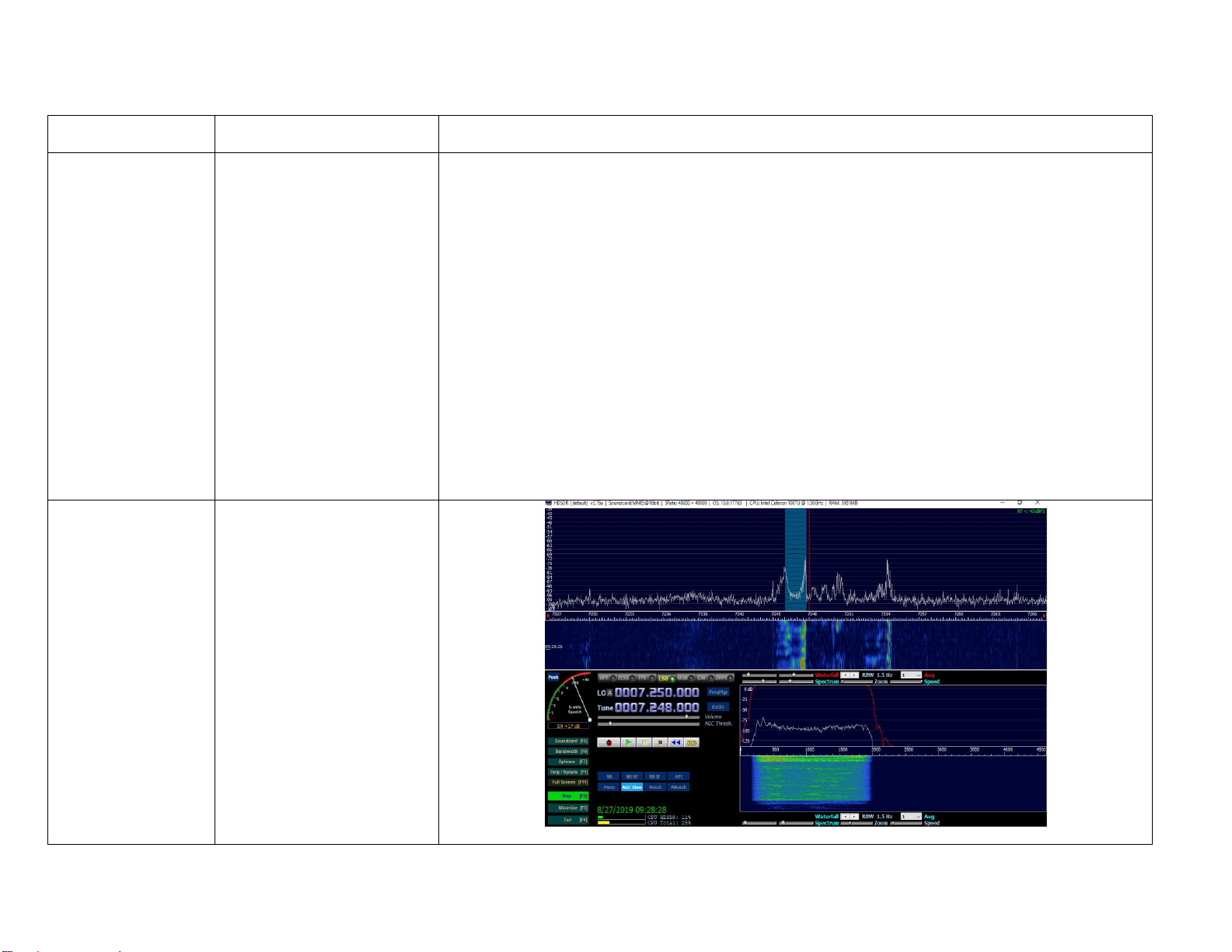
Short press USER-Knob(the bottom-left one):
Select filter center->Select filter bandwidth->Select USER-define->Loop back
When f-center is selected:Title will be "Cxxx"("xxx" is the center freq);a vertical green line showed up at
the middle of the orange area
When f-bandwidth is selected:Title will be "Bxxx"("xxx" is the bandwidth);two vertical green lines showed up
at the both sides of the orange area
4.Reset to factory settings
Press and hold "FUNC" key and turning the rig on to get access.
Press "PRE" key to confirm;press "VM" key to cancel
5.Main ref-clock fine tuning
Long press "FUNC" key and entering system menu,at item "7.RCLK Tune:"
If this parameter is messed up,just set it to "0",it neither damage the rig nor degrade the performance
6.Band stack mode
Long press "FUNC" key and entering system menu,at item "8.Band Stack Mode:"
it can be set as:HAM Band;Full Band
7.Power ON/OFF beeping
Long press "FUNC" key and entering system menu,at item "9.ON/OFF Beep:"
it can be set as:Disable;Enable
8.FFT averaging
2nd function of "LOCK" key,range can be in 1~10
Fixing and Optimization:
1.RX audio distortion caused by AGC;also AGC time constant is more longer(approximately,100ms@fast;1000ms@slow)
2.Cant power off when FFT Scale is too small
3.The DSP-filter icon sometimes don't draw correctly
4.2nd function menu behavior(menu or title at the multiple function display area):
Main display(DSP-filter icon)->2nd function title1->2nd function title 2->...2nd function title n->Loop back
5.Optimized NB algorithm(by the way,NB is not avaliable any more in AM mode in this version)
6.FFT SCALE can be saved at each band
7.Optimized APC algorithm
8.Optimized High SWR protection algorithm
9.Optimized RF output power detect algorithm(more accurate)
10.AM TX output power is down to 1/4 of the set power
11.Optimized voice comp algorithm
Other manuals for G90
10
Table of contents
Other XIEGU Transceiver manuals