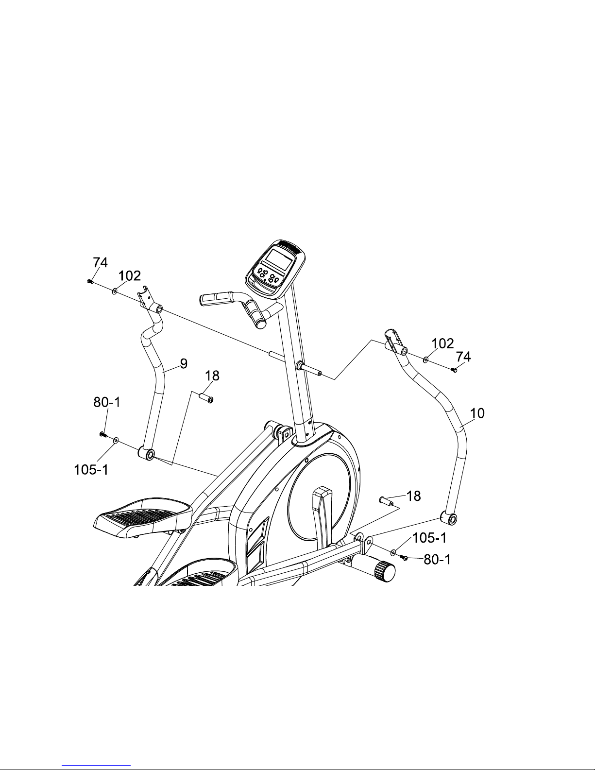
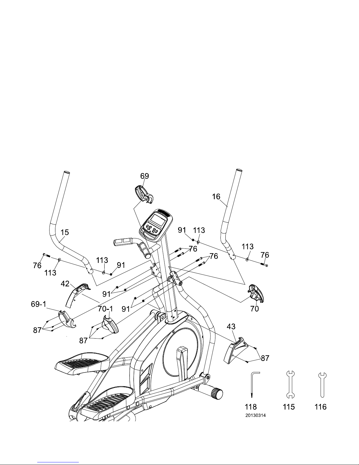
Xterra XTR0003 CARDIOFIT 2000 User manual

PLEASE CAREFULLY READ THIS ENTIRE MANUAL BEFORE OPERATING YOUR NEW ELLIPTICAL
CARDIOFIT 2000
ELLIPTICAL
OWNER’S MANUAL
- XTR0003 -

1
WARNING
-
Read all instructions before using this appliance.
■
Do not operate elliptical on deeply padded, plush or shag carpet. Damage
to both carpet and elliptical may result.
■
Keep children away from the elliptical. There are obvious pinch points and
other caution areas that can cause harm.
■
Keep hands away from all moving parts.
■
Never operate the elliptical if it has a damaged cord or plug. If the elliptical
is not working properly, call your dealer.
■
Keep the cord away from heated surfaces.
■
Do not operate where aerosol spray products are being used or where
oxygen is being administered. Sparks from the motor may ignite a highly
gaseous environment.
■
Never drop or insert any object into any openings.
■
Do not use outdoors.
■
To disconnect, turn all controls to the off position, then remove the plug
from the outlet.
■
Do not attempt to use your elliptical for any purpose other than for the
purpose it is intended.
■
The pulse sensors are not medical devices. Various factors, including the
user’s movement, may affect the accuracy of heart rate readings. The
pulse sensors are intended only as exercise aids in determining heart rate
trends in general.
■
Wear proper shoes. High heels, dress shoes, sandals or bare feet are not
suitable for use on your elliptical. Quality athletic shoes are recommended
to avoid leg fatigue.
SAVE THESE INSTRUCTIONS - THINK SAFETY!
CAUTION!! Please be careful when un-packing the carton.
CARDIOFIT 2000 XTR0003_Ver.A
Safety Hints

2
Assembly Pack Check List
STEP 1.
#104-1 Ø 8.7× 20 × 1.5T
Flat Washer
(2pcs)
#112. 3/8" × 23 × 1.5T
Curved Washer
(2pcs)
#80-1 5/16" × 15m/m
Button Head Socket Bolt
(2pcs)
#96. 3/8"
Cap Nut
(2pcs)
#77. 3/8" × 3"
Carriage Bolt (2pcs)
#82. M5 × 15m/m
Phillips Head Screw
(4pcs)
S
TEP
2
.
#105. 5/16" × 23 ×1.5T
Flat Washer
(4pcs)
#113. 5/16" × 23 × 1.5T
Curved Washer
(2pcs)
#80. 5/16" × 15m/m
Button Head Socket Bolt
(6pcs)
#111. 5/16" × 1.5T
Split Washer
(6pcs)
#84. M5 × 10m/m
Phillips Head Screw
(4pcs)

3
STEP
3
.
#102. Ø 8.7× 20 ×1.5T
Flat Washer
(2pcs)
#74. 5/16" × 15m/m
Hex Head Bolt
(2pcs)
STEP
4
.
#76. 5/16" × 1-3/4"
Hex Head Bolt
(6pcs)
#113. 5/16" × 23 ×1.5T
Curved Washer
(4pcs)
#91. 5/16" × 7T
Nyloc Nut
(6pcs)
#87. Ø3.5 × 12m/m
Sheet Metal Screw
(8pcs)
Assembly Pack Check List

4
Assembly Pack Check List
TOOLS
#116. 12 mm Wrench (1pcs)
#115. 13 &14 mm Wrench (1pcs)
#118. Combination 5mm Allen Wrench
& Phillips Head Screw Driver (1pcs)

5
STEP 1 Front Stabilizer and Connecting Arm Assembly
1. Install the Front Stabilizer(14) on the front stabilizer holding plate at the bottom of
the main frame with the transportation wheels facing forward and secure them with
2pcs of 3/8" × 3" Carriage Bolts(77), 2pcs of 3/8" × 23m/m × 1.5T Curved
Washers(112) and 2pcs of 3/8" Cap Nuts(96) by using 13.14m/m Wrench(115).
2. Secure 2pcs slide wheel cover (65) on left and right pedal arm (5) with four M5 ×
15m/m Phillips Head Screws (82) by using Combination M5 Allen Wrench &
Phillips Head Screw Driver (118).
3. Insert the shaft on left connecting arm (7) to the bushing on left pedal arm (5) and
secure with 1pcs 5/16" × 15m/m Button Head Socket Bolt (80-1) together with
1pcs Ø8.7 × 20 ×1.5T Flat Washer (104-1) by using Combination M5 Allen Wrench
& Phillips Head Screw Driver (118). Do it the same way for right connecting arm (8)
and right pedal arm (5).
Assembly Instructions

6
STEP 2 Console Mast Assembly
1. Use cable tie to guide the 1150m/m Computer Cable(36) through Console Mast(11)
and then pull out of the console holding plate, and Insert the console mast into
main frame and secure with 6pcs of 5/16" × 15m/m Button Head Socket Bolts(80),
6pcs of 5/16" × 1.5T Split Washers(111), 4pcs of 5/16" × 23m/m × 1.5T Flat
Washers(105) and 2pcs of 5/16" × 23m/m × 1.5T Curved Washers(113) by using
Combination M5 Allen Wrench & Phillips Head Screw Driver(118) .
2. Take off the cable tie which ties the Computer Cable(36) and plug in the
connectors of the Computer cable and the two Handpulse W/Cable Assemblies(40)
on the Console. Secure the Console on the Console Assembly(35) with 4pcs of
M5 × 10m/m Phillips Head Screws(84) by using Combination M5 Allen Wrench &
Phillips Head Screw Driver(118). Pay attention to Avoiding scratching the cables.

7
STEP 3 Handle Bar Assembly
1. Install the Lower Handle Bar (L) (9) in the left shaft of Console Mast(11) and the
Lower Handle Bar (R) (10) in the right shaft of Console Mast(11), and secure them
with 2pcs of 5/16" × 15m/m Hex Head Bolts(74) and 2pcs of Ø8.7 × 20m/m × 1.5T
Flat Washers(102) by using 12m/m Wrench(116).
2. Release rod end shafts (18) which are on left and right connecting arms. Connect
the connecting arm with lower handle bar and secure with rod end shafts (18) and
the screw by using Combination M5 Allen Wrench & Phillips Head Screw Driver
(118) and 12m/m_Wrench(116).

8
STEP 4 Connecting Arm Assembly
1. Connect the Swing Arm (L) (15) to the left Lower Handle Bar and connect the
Swing Arm (R) (16) to the right Lower Handle Bar, and secure them with 6pcs of
5/16" ×1-3/4" Hex Head Bolts(76),4pcs of 5/16" × 23m/m × 1.5T Curved
Washers(113) and 6pcs of 5/16" × 7T Nyloc Nuts (91) by using 12m/m
Wrench(116) 13.14m/m Wrench(115).
2. Put the Front Handle Bar Cover (L) (69) and the Rear Handle Bar Cover (L) (69~1)
together on the left Handle Bar and secure with 3pcs of Ø3.5 × 12m/m Sheet
Metal Screws(87) by using Combination M5 Allen Wrench & Phillips Head Screw
Driver(118). Repeat the same procedure for the right side.
3. Connect the Console Mast Cover (L)(42) and the Console Mast Cover (R)(43)
together on the Console Mast and secure with 2pcs of Ø3.5 × 12L_Sheet Metal
Screw(87) by using Combination M5 Allen Wrench & Phillips Head Screw
Driver(118).

9
Key Functions
START/STOP: 1. Starts & pauses workouts.
2. Starts body fat measurement.
3. Holding key for 3 seconds will reset all function values to zero.
DOWN: Decrease value of selected workout parameter: TIME, DISTANCE, etc.
During the workout, it will decrease the resistance load.
UP : Increases value of selected workout parameter. During the workout, it will increase the
resistance load.
ENTER: To input desired value or work out mode.
RECOVERY: Press to enter into Recovery function when computer has the heart rate
value. Recovery is Fitness Level 1-6 after 1 minute.F1 is the best, and F6 is
the worst.
MODE: Press to switch display form RPM to SPEED, ODO to DIST, WATT to CALORIES
during workout.
Console

10
Workout Selection
After power-up using UP or DOWN keys to select then pressing ENTER to enter the
desired mode.
There are 7 basic workout modes:
Manual, Pre- programs, Watt Program, Body Fat Program, Target Heart Rate program,
Heart Rate Control program and User Program.

11
Functions:
1. SPEED: Displayscurrent training speed. Maximum speed is 99.9 KM/H or MILE/H.
2. RPM: Displayscurrent rotation per minute.
3. TIME: Accumulatesthe workout time from 00:00 to 99:59. Or users can preset the
target time they want.
4. DIST: Accumulatesthe workout distance from 0.00 up to 999.9 KMsor Miles. Or users
can preset the target distance they want to reach.
5. ODO: Displaysthe total accumulated distance from 0.0 to 999.9KMsor Miles
6. CAL: Accumulatesthe calorie consumption from 0 to 9999. Or users can preset the
target calories they want to consume.
7. WATT: Displayscurrent watts.
8. HEART RATE: Displaysthe current heart rate in beats per minute.
9. TARGET .H. R.: Users can preset their Target Heart Rate.
10. PROGRAM: There are 24 different programs to choose for training.
11. LEVEL: The program has 24 levels loading and 8 bars in each column. Each column
represents 1 minute workout (without the change of time value) and each bar
represents 3 levels loading.
12. Music playing
:
There is an audio-input port on the top of the monitor, The user can
connect the MP3 to the Audio-input , and turn on the MP3 ,to play music.
Workout Parameters
:
TIME / DISTANCE / CALORIES /AGE/WATT/TARGET HEART RATE
Setting Workout Parameters
After selecting desired workout mode: Manual, Pre-set Programs, Watt Program, Body
Fat, Target Heart Rate, Heart Rate Control and User Program. You may pre-set several
workout parameters for desired results.
Note: Some parameters are not adjustable in certain programs.
Time and Distance can not be set up at the same time.
Once a program has been selected, pressing ENTER, will make “Time” parameter flash.
Using UP OR DOWN KEY you may select desired time value. Press ENTER KEY to input
value.
Flashing prompt will move to the next parameter. Continue use of UP OR DOWN KEY.
Press START/STOP to start workout.

12
More About Workout Parameters
Field Setting Range
Default
Value
Increment/
Decrement Description
Time
0:00~ 99:00 00:00 ± 1:00
1.When display is 0:00, Time
will count up.
2.When time is 1:00-99:00,
It will count down to 0.
Distance
0.00~999.0 0.00 ±1.0
1.When display is 0.0,
Distance will count up.
2.When Distance is 1.0~999.0,
it will count down to 0.
Calories
0~9995 0.0 ±5
1.When display is 0, Calories
will count up.
2.When Calories is 5~9995,
it will count down to 0.
Watt 40~250 100 ±5 User can set watt value only in
Watt control program.
Age 10~99 30 ±1
Target HR will be based on
Age. When Heart Rate
exceeds Target H.R, the
number of Heart Rate will flash
Pulse 60~220 90 ±1 Setting Parameters for Target
heart rate
Program Operation
Manual
(
((
(
P1
)
))
)
Program profile
Selecting “Manual” using UP OR DOWN KEY then pressing ENTER KEY.
1
St
parameter “Time” will flash so value can be adjusted using UP OR DOWN KEY .Press
ENTER KEY to save value & move to next parameter to be adjusted.
**(If user sets up the target time to workout, then the next parameter of Distance can
not be adjusted)
Continue through all desired parameters, pressing START/STOP to start workout.
Note: Once the workout parameter counts down to be zero, it will beep and stop the
workout automatically. Press START KEY to continue the workout to reach the
unfinished workout parameter.

13
Pre-programs (P2~P13)
Program profile
ROLLING
VALLEY
FAT BURN
RAMP
STEPS OBSTACLE
INTERVALS
PLATEAU
CLIMBING
OFF ROAD
HILL PEAK INTERVALS
There are 12 program profiles ready for use
:
::
:
ROLLING, VALLEY, FAT BURN,
RAMP, STEPS, OBSTACLE, INTERVALS, PLATEAU, CLIMBING, OFF ROAD,
HILL and PEAK INTERVALS.All program profiles have 24 levels of resistance.

14
Setting Parameters for Pre-programs
Select one of pre-programs using UP OR DOWN KEY then pressing ENTER KEY.
1
St
parameter “Time” will flash so value can be adjusted using UP OR DOWN KEY .Press
ENTER KEY to save value & move to next
parameter to be adjusted. Continue through all desired parameters, pressing START/STOP
to start workout.
Workout in any pre-program
Users can exercise with different levelsof loading in different intervals as the profiles flash.
Users may exercise in any desired level of resistance by adjusting by UP/DOWN keys
during the workout.
Note: If user sets up the target time to workout, then the next parameter of Distance can
not be adjusted. Once the workout parameter counts down to zero, it will beep and stop the
workout automatically. Press START/STOP to continue the other unfinished parameters.
Watt control program(P14)
Program profile
Setting Parameters for Watt control program
Selecting “Watt control program” using UP OR DOWN KEY then pressing ENTER KEY.
1
St
parameter “Time” will flash so value can be adjusted using UP OR DOWN KEY .Press
ENTER KEY to save value & move to next parameter to be adjusted.
**(If user sets up the target time to workout, then the next parameter of Distance can
not be adjusted)
Continue through all desired parameters, pressing START/STOP to start workout.
Note: One of workout parameters counts down to be zero, it will have bi sounds and stop
the workout automatically. Press START KEY to continue the workout to reach the
unfinished workout parameter.
Computer will adjust the resistance load automatically depending on the speed
needed to maintain the constant watt value. User can use up down key to adjust the
watt value during workout.
BODY FAT PROGRAM
Program profile

15
Setting Data for Body Fat
Select “BODY FAT Program ” using UP OR DOWN KEY then press ENTER.
“Male” will flash so Gender can be adjusted using UP OR DOWN KEY, press ENTER to
save gender & move to next data.
“ 175” of Height will flash. Height can be adjusted using UP OR DOWN KEY , press
ENTER to save value & move to next data.
“ 75 “of Weight will flash so Weight can be adjusted. Use UP OR DOWN KEY , press
ENTER KEY to save valve & move to next data.
“30” of Age will flash so Age can be adjusted using UP OR DOWN KEY, press ENTER to
save value.
Press START/STOP to start measurement, please also grasp hand pulse grips.
After 15 seconds the display will show out Body Fat %, BMR, BMI & BODY TYPE.
NOTE: Body Types:
There are 9 body types divided according to the FAT% calculated. Type 1 is from
5% to 9%. Type 2 is from 10% to 14%. Type 3 is from 15% to 19%. Type 4 is
from 20% to 24%. Type 5 is from 25% to 29%. Type 6 is from 30% to 34%.
Type 7 is from 35% to 39%. Type 8 is from 40% to 44%. Type 9 is from 45% to
50%.
BMR: Basal Metabolism Ratio
BMI: Body Mass Index
Press START/STOP KEY to return the main Display.
TARGET HEART RATE Program
Program profile
Setting Parameters for TARGET H.R
Select “TARGET H.R.” using UP OR DOWN KEY then pressing ENTER KEY.
1
St
parameter “Time” will flash so value can be adjusted using UP OR DOWN KEY .Press
ENTER KEY to save value & move to next parameter to be adjusted.
**(If user sets up the target time to workout, then the next parameter of Distance can
not be adjusted)
Continue through all desired parameters, pressing START/STOP to start workout.
Note: If Pulse is above or below (± 5) the setting TARGET H.R, the computer will adjust the
resistance load automatically. It will check every 10 seconds approx. l level load will
increase or decrease (Note: each resistance load represents 3 levels of
loading).when the heart rate signal disappears, the computer will keep the
resistance load constant for 60s, then it will decrease the resistance load 1 level per
10s.
When one of the workout parameters counts down to be zero, it will beep and stop
the workout automatically. Press START/STOP to continue the other unfinished
parameters.

16
HEART RATE CONTROL Program
Program profile
There are 4 selection for target pulse:
HRC- 55% TARGET H.R= 55% of (220-AGE)
HRC - 65% TARGET H.R= 65% of (220-AGE)
HRC - 75% TARGET H.R= 75% of (220-AGE)
HRC - 85% TARGET H.R= 85% of (220-AGE)
Setting Parameters for HEART RATE CONTROL
Selecting “One of Heart Rate Control Program .” using UP OR DOWN KEY then pressing
ENTER KEY . 1
St
parameter “Time” will flash so value can be adjusted using UP OR
DOWN KEY .Press ENTER KEY to save value & move to next parameter to be
adjusted.
**(If user sets up the target time to workout, then the next parameter of Distance can
not be adjusted)
Continue through all desired parameters, pressing START/STOP to start workout.
Note: If Pulse is above or below (± 5) the setting TARGET H.R. the computer will adjust the
resistance load automatically. It will check Every 10 seconds approx. l level load will
increase or decrease (Note: each resistance load represents 3 levels of
loading).when the heart rate signal disappeared, the computer will keep the
resistance load constant for 60s, then it will decrease the resistance load 1 level per
10s.
One of workout parameters counts down to be zero, it will have bi sounds and stop
the workout automatically. Press START/STOP KEY to continue the workout to
reach unfinished workout parameter.

17
Wearing The Chest Strap
(Sold Separately)
1. Attach the transmitter to the elastic strap using the locking
parts.
2. Adjust the strap as tightly as possible as long as the strap
is not too tight to remain comfortable.
3. Position the transmitter with the logo centered in the
middle of your torso facing away from your chest (some
people must position the transmitter slightly left of center).
Attach the final end of the elastic strap by inserting the
round end and, using the locking parts, secure the
transmitter and strap around your chest.
4. Position the transmitter directly below the pectoral
muscles.
5. Sweat is the best conductor to measure very minute heart beat electrical signals.
However, plain water can also be used to pre-wet the electrodes (2 ribbed oval areas on the
reverse side of the belt and both sides of the transmitter). It’s also recommended that you
wear the transmitter strap a few minutes before your work out. Some users, because of
body chemistry, have a more difficult time in achieving a strong, steady signal at the
beginning. After “warming up”, this problem lessens. As noted, wearing clothing over the
transmitter/strap doesn’t affect performance.
6. Your workout must be within range - distance between transmitter/receiver – to achieve a
strong steady signal. The length of range may vary somewhat but generally stay close
enough to the console to maintain good, strong, reliable readings. Wearing the transmitter
directly on bare skin assures you of proper operation. If you wish, you may wear the
transmitter over a shirt. To do so, wet the areas of the shirt that the electrodes will rest upon.

18
User Program
Program profile
4 User program allow user to set their own program that can be used immediately.
Setting Parameters for User Program
Selecting user
using UP OR DOWN KEY then pressing ENTER KEY.
1
St
parameter “Time” will flash so value can be adjusted using UP OR DOWN
KEY .Press ENTER KEY to save value & move to next parameter to be adjusted.
**(If user sets up the target time to workout, then the next parameter of Distance
can not be adjusted)
Continue through all desired parameters
.
After finishing the set up of your desired parameters, the level 1 will flash, use UP OR
DOWN KEY to adjust then pressing ENTER until finished. (There are 10 times total).
Press START/STOP to start workout.
Note: Once the workout parameter counts down to be zero, it will beep and stop the
workout automatically. Press START/STOP KEY to continue the workout to
reach unfinished workout parameter.

19
NO.
DESCRIPTION
O'TY
1
Main Frame
1
3
Crank Arm Assembly
2
5
Pedal Arm(L)
1
7
Connecting Arm (L)
1
8
Connecting Arm (R)
1
9
Lower Handle Bar (L)
1
10
Lower Handle Bar (R)
1
11
Console Mast
1
12
Idler Wheel Assembly
1
13
Crank Axle
1
14
Front Stabilizer
1
15
Swing Arm (L)
1
16
Swing Arm (R)
1
18
Rod End Shaft(Blackfast)
2
19
Axle for Slide Wheel
(Blackfast)
2
22
Aluminum Track
2
23
6005_Bearing
2
24
6003_Bearing
4
25
Axle for Idler Wheel
1
27
Belt
1
28
Flywheel
1
29
Magnet
1
30
Handgrip Foam
2
31
Steel Cable
1
35
Console Assembly
1
36
1600m/m_Computer Cable
1
37
450m/m_DC Power Cord
1
38
Gear Motor
1
39
200m/m_Sensor W/Cable
1
40
800m/m_Handpulse W/Cable Assembly
2
41
Power Adaptor
1
42
Console Mast Cover (L)
1
43
Console Mast Cover (R)
1
44
Transportation Wheel
2
Parts List
Table of contents
Other Xterra Elliptical Trainer manuals

Xterra
Xterra FS400 User manual

Xterra
Xterra FS5.9e User manual

Xterra
Xterra FS5.5e User manual

Xterra
Xterra FS4.0e User manual

Xterra
Xterra XE570S User manual

Xterra
Xterra FS420e User manual

Xterra
Xterra FS5.8e User manual

Xterra
Xterra 164174535US User manual

Xterra
Xterra 164174500US User manual

Xterra
Xterra FS3.5 User manual

Xterra
Xterra FS5.4e User manual

Xterra
Xterra 16604701500 User manual

Xterra
Xterra FS2.5 User manual

Xterra
Xterra FS220e User manual

Xterra
Xterra 16417320 User manual

Xterra
Xterra FS5.3e User manual

Xterra
Xterra 16417681US User manual

Xterra
Xterra FS3.0 User manual

Xterra
Xterra FSX3500 User manual

Xterra
Xterra FS5.25e User manual