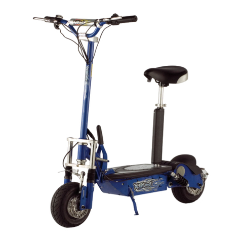
Xtreme XT300 User manual

X-TREME 4 WHEEL
ELECTRIC PERSONAL TRANSPORTER
Model XT300
Due to continuing improvements, actual product may differ slightly from the product described herein.
Visit our Web site at: http://www.x-tremescooters.com/
TO PREVENT SERIOUS INJURY, READ
AND UNDERSTAND ALL WARNINGS
AND INSTRUCTIONS BEFORE USE.
Page 1

PRODUCT SPECIFICATIONS
Item Description
Electrical Requirements Input power: AC90V-260V
Charge Time: 4-8 Hours
Output power: 36VDC
Battery Type:36VDC, 12AH, Lead Acid (Rechargeable)(Qly.3)
Motor Type:250 watt (Qty . 2)
Fuse Type: F30A110V-Batteries
F2A250V-Instrument panel and controls
Bulb Type: Turn Signals = YH/3W40V / Headlight=40Volt, 10 Watt
Power Cord Type: 18AWG×2C
Power Cord Plug Type:3-Prong power cable
Maximum Weight Capacity 250 Pounds
Maximum Speed Approximately 10 MPH (Depending On Weight Of Operator)
Maximum Travel Time
(On One Charge)
Approximately 15 Miles
Drive Type / Brake Type Belt Drive / Rear Wheel Disc
Wheel Types Front = 16”×2-1/8” Air tire (Qty.2)
Rear = 6”×1-1/4” Solid tire (Qty.2)
Overall Dimensions 50-3/4”H×23-1/2”W×28-1/2”L
Unit Weight 114 Pounds
Standard Features Forward & Reverse Modes / Foldable Handle / Key lgnition
Adjustable Height Handlebars / Headlight / Electric Horn
Front Facing Left & Right Turn Signals / Battery Indicator Gauge
Speed Indicator Gauge / LED Power & headlight Display / Battery Charger
Warning: This Scooter is not designed to be driven on roads. Streets., highways,
or other public roadways. Never operate the Scooter off-road or off-paved surfaces.
SAVE THIS MANUAL
You will need this manual for the safety warnings and precautions, assembly, operating,
inspection, maintenance and cleaning procedures, parts list and assembly diagram.
Keep your invoice with this manual. Write the invoice number on the inside of the front cover.
Keep this manual and invoice in a safe and dry place for future reference.
UNPACKING
When unpacking, check to make sure all the parts shown on the Parts Lists on pages 12
through 15 are included.
Page 2

1. This product is intended for adult use only. Do not allow children to ride on or play
with the XT-300.
2. IMPORTANT: Your insurance policies may not provide coverage for accidents involving
the use of this Scooter. To determine if coverage is provided, you should contact your
insurance company or agent.
3. Do not operate the Scooter in explosive atmospheres, such as in the presence of
flammable liquids, gases, or dust. Electrically powered products create sparks, which
may ignite the dust or fumes.
4. Keep bystanders, children, and visitors away while operating your XT-300.
Distractions can cause you to lose control.
5. Do not expose the Scooter to rain or wet conditions. Water entering electrically
powered products will increase the risk of electric shock.
6. Stay alert. Watch what you are doing, and use common sense when operating the
XT-300. Do not use this product while tired or under the influence of drugs, alcohol,
or medication. A moment of inattention while operating the XT-300 may result in serious
personal injury.
7. Never carry a passenger on the XT-300. This Scooter is designed for single rider only.
8. This Scooter is designed to be operated only on dry, flat, paved surfaces. Never
operate the XT-300 off-road. Never operate the XT-300 on roads, streets, highways, or
any other public roadways.
9. Always obey local laws and regulations for operating your XT-300.
10. The XT-300 is not designed for racing or performing tricks. Always ride responsibly.
11. DO not attempt to exceed the weight carrying capacity of 250Lbs.
12. Do not allow other adults to use the XT-300 without proper instructions.
13. Avoid accidental starting. Make sure the ignition Key is removed and the ignition is
off when not in use.
WARNING!
READ AND UNDERSTAND ALL INSTRUCTIONS
Failure to follow all instructions listed below may
result in
Electric shock, fire, and/or serious injury.
SAVE THESE INSTRUCTIONS
GENERAL SAFETY RULES
Page 3

14. Do not overreach. Keep proper footing and balance at all times. Proper footing and
balance enables better control in unexpected situations.
15. Do not use the XT-300 if the ignition Key does not turn it on or off. Any vehicle that
cannot be controlled with the ignition Switch is dangerous and must be replaced.
16. Make sure to remove all adjusting tools from the Scooter before starting. A wrench
or screwdriver that is left attached to a rotating part may result in personal injury and/or
product damage.
17. Maintain labels and nameplates. These carry important information.
18. Disconnect the charger from its power source and the XT-300 before making any
adjustments, changing accessories, or storing the unit. Such preventive safety
measures reduce the risk of starting the Scooter accidentally.
19. DO not abuse the charger. Never use the charger to pull the XT-300 or pull the
charger plug from any outlet. Keep the charger cord away from heat, oil, sharp
edges, or moving parts. Replace a damaged charger immediately. A damaged
Charger increases the risk of electric shock.
20. When operating the XT-300, always maintain a firm grip on the Handle Bars with
both hands to maintain control.
21. Do not over-stress the XT-300. This product will be easier and safer to ride at the speed
and capacity for which it was designed.
22. The charge time for the Battery is 5 hours. Do not charge the Battery for over 5 hours,
as damage to the Battery and/or XT-300 may result.
23. Always recharge the Battery when Scooter performance begins to diminish. Severe
heat is most destructive to a Battery. The more heat generated, the faster the Battery
loses its power. A Battery that gets too hot can be permanently damaged. Never
over-discharge a Battery by using the Scooter after Scooter performance has decreased.
Never attempt to discharge the Scooter’s Battery by continuing to operate the unit. When
performance begins to diminish, stop and recharge the Battery for optimal performance.
See p.8 “To Charge The Battery” for more information.
24. Battery leakage may occur under extreme usage or temperature conditions. If
Battery fluid comes in contact with skin, wash with soap and water and rinse with lemon
juice and vinegar. If the fluid comes into contact with eyes, flush with water for several
minutes and contact a physician immediately.
Page 4

25. Never burn a Battery, as it can explode in a fire. Contact local solid waste authorities
for instructions on correct disposal of a Battery.
26. Do not attempt to charge a leaking Battery.
27. Use only accessories that are recommended by X-Treme Scooters for your XT-300.
Accessories that may be suitable for one scooter may become hazardous when used on
another.
28. Store the XT-300 out of reach of children and other untrained persons. Electrically
powered products are dangerous in the hands of untrained users.
29. Maintain your XT-300 with care. Keep the unit clean and dry. Properly maintained
products are less likely to malfunction and are easier to control. Do not use the Scooter if
damaged.
30. Check for misalignment or binding of moving parts, breakage of parts, and any
other condition that may affect the Scooter’s operation. If damaged, have the
Scooter serviced before using. Many accidents are caused by poorly maintained
products.
31. Scooter service must be performed only by qualified repair personnel. Service or
maintenance performed by unqualified personnel could result in a risk of injury.
32. When servicing the Scooter, use only identical replacement parts. Follow
instructions in the “Inspection, Maintenance, And Cleaning” section of this manual.
Use of unauthorized parts or failure to follow maintenance instructions may create a risk of
electric shock or injury.
33. Never leave the Scooter unattended without first turning the lgnition to its “OFF”
position and removing the lgnition Key.
34. WARNING! People with pacemakers should consult their physician(s) before using
this product. Operation of electrical equipment in close proximity to a heart pacemaker
could cause interference to or failure of the pacemaker.
35. WARNING! The warnings and cautions discussed in this manual cannot cover all
possible conditions and situations that may occur. It must be understood by the operator
that common sense and caution are factors, which cannot be built into this product, but
must be supplied by the operator.
Page 5

ASSEMBLY AND OPERATING INSTRUCTIONS
1. CAUTION! Always make sure the ignition switch is in its “OFF” position and the
ignition Key is removed prior to setting up the XT-300, adding any accessories, or making
adjustments to the unit.
2. The Scooter comes fully assembled, but will require some setup as follows: The Steering
Bar Assembly must be positioned in place, the Wheels must be inflated and the Batteries
must be charged.
Raise, lock, And Adjust The Steering Bar Assembly:
1. Remove the Bolt illustrated below. (See Figure A.)
2. Lift the Steering Bar Assembly all the way up to its vertical position. Then, insert the Bolt
you removed previously back into the same hole and firmly tighten it. (See Figure A.)
3. Push the Quick Release Lever (C9) down to lock the Handle Bar in place. (See Figure A.)
4. To adjust the height of the Handle Bar, unlatch the Quick Release Lever (C9). Adjust the
Handle Bar to a comfortable height. Then, lock the Quick Release Lever (C9) in place.
(See Figure A.)
Install Power Pack Plug
1. Lay the XT-300 down so that you can locate the power pack plug under the scooter on the
left side.
2. Insert the plug into the power pack as show below.
3. Return the scooter to its upright position.
Page 6

Inflate The Wheels:
Make sure to inflate the front and back Wheels to 36 PSI.Do not exceed 36 PSI. Use
compressed air only.
Product Features:
Page 7

To Charge The Batteries:
1. Before riding the Scooter for the first time you must charge the Batteries. Thereafter, if
performance diminishes and/or the Voltage Gauge drops below 30V,you must
recharge the Batteries.
2. Make sure the lgnition is in the “OFF” position. (See Figure B.)
3. Plug the Charging Plug into the Scooter’s Power inlet Socket first, making sure to tighten
the ring of the Socket to hold the Charging Plug in place. Then, plug the 3-Prong Power
Cord Plug into the nearest 120 Volt, grounded, electrical outlet. (See Figure C.)
4. Charge the Scooter for 5 hours. A red LED light will illuminate on the Gauge Panel of the
Scooter while it is being charged. Once the Scooter is fully charged, the red LED Light will
automatically turn to green. Note: when the Voltage Gauge on the Gauge Panel indicates
42V-43V that also means a full charge. If the Voltage Gauge indicates lower than 30V, you
must charge the Batteries. (See Figures B and C.)
5. IMPORTANT: Do not charge the Scooter for more than 5 hours. Overcharging may limit
the life of the Scooter’s Batteries. Unplug after 5 hours to avoid overheating the Batteries.
Page 8

6. When the LED Light on the Gauge Panel turns to green, unplug the 3-Prong Power Cord
Plug from its electrical outlet. Then, unscrew the ring of the Scooter’s Power Inlet Socket
and disconnect the Charging Plug from the Socket. (See Figure C.)
Pre-operating Safety Checks:
1. Before operating the Scooter, make sure to perform the following safety checks:
A.Squeeze the Brake Handle, and push the Scooter to see if it rolls easily. If so, you will
need to tighten the Brakes. Each of the Rear Tires has its own Brake. To tighten, tilt the
Scooter forward to expose the undercarriage, and on either the Right or Left Rear Wheel,
loosen the Bolt on the Brake Arm that secures the Brake Cable. Next, while holding the
end of the Brake Cable, press down on the Brake Arm and Firmly retighten the Bolt
B.Repeat Step A. above on the other Brake. Upright the Scooter, and perform Brake Test
again by squeezing Brake Handle and pushing the Scooter.
2. While the Scooter is off,apply the Thumb Throttle and release. Check to make sure the
Throttle springs back to “stop” after you release it. (See Figure B.)
3. Check the Wheels (12, 24) for wear and proper air pressure (36 PSI).(See Assy. Diagram
on page 12.)
4. Check to make sure the Headlight, Turn Signal Lights, and Horn are working properly.
(See Figure B.)
Operating points:
1. WARNING: This Scooter is not designed to be driven on roads, streets, high ways, or
other public roadways. Never operate the Scooter off-road or off-paved surfaces.
2. Turn the lgnition Key to the “ON” position before starting the Scooter. (See Figure B.)
3. Apply the Thumb Throttle to move forward. Do not ride the Brakes. Release the Thumb
Throttle before braking. NOTE: The Scooter is equipped with an electrical braking system.
This means when you engage the Brakes, the Thumb Throttle is inoperative. (See Figure
B.)
4. The Scooter works best on level ground. Use caution while riding up inclines. Excess
climbing will limit the life of the Batteries and can be very dangerous.
5. Operate the Scooter only in good weather. Using the Scooter in rain or snow may result in
damage to the Scooter and/or personal injury to the operator.
6. Do not jump curbs, perform tricks, or ride on one Wheel.
7. Obey the laws in the city where you are riding the Scooter.
8. Do not leave the XT-300 in direct sunlight for an extended period of time.
Page 9

9. When finished riding the Scooter, gradually apply the Brakes until you come to a complete
stop. Then, turn the lgnition Key to its “OFF” position. (See Figure B.)
10. Make sure to remove the lgnition Key. Then, store the Scooter in a clean, dry location out
of reach of children.
INSPECTION, MAINTENANCE, AND CLEANING
1. WARNING! Make sure the lgnition of the Scooter is in its “OFF” position and the
Charging Plug is removed from the unit before performing any inspection, maintenance,
or cleaning procedures.
2. Before each use, inspect the general condition of the Scooter. Check for loose screws.
Misalignment or binding of moving parts, cracked or broken parts, and damaged electrical
wiring. Check the Thumb Throttle, Brakes, Wheels, Headlight, Turn Signals, Horn, and
any other condition that may affect its safe operation. If abnormal noise or vibration occurs,
have the problem corrected before further use. Do not use damaged equipment.
3. If stored for an extended period of time: Charge the Battery at least once every 90
days. To prolong the life of the Batter, discharge the Battery every 90 days. Only a
qualified service technician should replace the Battery.
4. To clean, use a clean, damp cloth and a mild detergent. Do not use solvents.Do not spray
water on the Scooter. Excessive exposure to water may damage the Scooter.
5. To replace the Instrument Panel Fuse: The Scooter uses an F2A250V Fuse which is
located on the Gauge Panel. If necessary, Unscrew and remove the Fuse Cap. Replace
the blown Fuse with a new Fuse. Then, replace the Fuse Cap. (See “Troubleshooting
“ section.)
6. To replace the Battery Fuse: The Scooter uses an F30A110V Fuse which is located
between the left side of Battery Case and the inside part of the Steel Frame. (See
“Troubleshooting “ section.)
7. CAUTION! All maintenance, service, or repairs not mentioned in this manual
must only be performed by a qualified service technician.
Page 10

PLEASE READ THE FOLLOWING CAREFULLY
THE MANUFACTURER AND/OR DISTRIBUTOR HAS PROVIDED THE PARTS LIST AND
ASSEMBLY DIAGRAM IN THIS MANUAL AS A REFERENCE TOOL ONLY. NEITHER THE
MANUFACTURER OR DISTRIBUTOR MAKES ANY REPRESENTATION OF WARRANTY
OF ANY KIND TO THE BUYER THAT HE OR SHE IS QUALIFIED TO REPLACE ANY
PARTS OF THE PRODUCT. IN FACT, THE MANUFACTURER AND/OR DISTRIBUTOR
EXPRESSLY STATES THAT ALL REPAIRS AND PARTS REPLACEMENTS SHOULD BE
UNDERTAKEN BY CERTIFIED AND LICENSED TECHNICIANS, AND NOT BY THE BUYER.
THE BUYER ASSUMES ALL RISKS AND LIABILITY ARISING OUT OF HIS OR HER
REPAIRS TO THE ORIGINAL PRODUCT OFR REPLACEMENT PARTS THERETO, OR
ARISING OUT OF HIS OR HER INSTALLATION OF REPLACEMENT PARTS THERETO.
.
TROUBLESHOOTING
Problem Possible Cause Possible Solution
The power light on the gauge
panel does not light up when the
Scooter is turned on.
1. Battery is discharged.
2. Blown instrument Panel Fuse.
3. Loose electrical connect on inside
the Scooter.
1. Recharge Battery for 5 hours.
(See page 8.)
2. Replace Fuse.
(See page 10.)
3. Have a qualified service
technician examine the
connections.
The power light on the gauge
panel lights up, but Scooter still
does not start.
1. The thumb throttle is not operating
properly.
1. Have a qualified service technician
examine the thumb throttle.
The power light on the gauge
panel does not light up, and the
Scooter does not start.
1. Blown Battery Fuse.
1. Replace Fuse.
(See page 10.)
When brake lever is squeezed,
Scooter does not stop.
1. Brakes are not adjusted properly. 1. Properly adjust brakes.
(See page 9.)
Scooter is moving slower and
slower.
1. Low battery.
2. Battery is defective.
1. Recharge battery for 5 hours.
(See page 8.)
2. Have a qualified service technician
replace battery.
Page 11

NOTE: Some parts are listed and shown for illustration purposes only, and are not available individually as
replacement parts.
Part Description Q’ty Part Description Q’ty
1 Spring Washer 4 14 Pulley Block 1
2 Inner Steering Arm 1 15 Hex Nut 2
3 Cam Flange 1 16 Hex Nut 2
4 Seal 1 17 Hex Key Screw 4
5 Retaining Ring 1 18 Hex Lock Nut 1
6 Circuit Board 1 19 Hex Key Screw 5
7 Battery Case 1 20 Hex Bolt 1
8 Panel 1 21 Hex Bolt 1
9 Scooter Frame 1 22 Bearing 2
10 Rear Wheel Bracket
(See List and Diagram A) 1 23 Left Brake 1
11 Coupling Bar 1 24 Front Wheel 2
12 Wheel Assembly
(See List and Diagram B) 2
13 Steering Bar Assembly
(See List and Diagram C) 1
PARTS LIST & ASSEMBLY DIAGRAM - SCOOTER
Page 12

PARTS LIST & ASSEMBLY DIAGRAM A – REAR WHEEL BRACKET
PART A Rear Wheel Bracket
Part Description Qty.
A1 Ball Bearing 4
A2 Retaining Ring 2
A3 Retaining Ring 2
A4 Retaining Ring 4
A5 Flat Washer 10
A6 Pin 2
A7 Cam Bracket 1
A8 Transverse Coupling Bar 2
A9 Cam Flange 2
A10 Pin 2
A11 Frame 1
A12 Ball Bearing 5
A13 Hex Screw 2
A14 Hex Key Screw 2
NOTE:
Some parts are listed and shown for illustration purposes only,
and are not available individually as replacement parts.
Page 13

PARTS LIST & ASSEMBLY DIAGRAM B
–
WHEEL ASSEMBLY
Part Description Q’ty
B1 Ball Bearing 2
B2 Brake Rotor 1
B3 Inner Hub 1
B4 Outer Hub 1
B5 Hex Locking Screw 1
B6 Cap Screw 1
B7 Cross Countersunk Screw 6
B8 Cap Screw 3
B9 Bushing 1
B10 Flat Hook Washer 2
B11 Wheel 1
NOTE:
Some parts are listed and shown for illustration purposes only,
and are not available individually as replacement parts.
Page 14

PARTS LIST & ASSEMBLY DIAGRAM C
–
STEERING BAR ASSY.
Part Description Q’ty
C1 Column 1
C2 Seal 1
C3 Dust Cover 1
C4 Handlebar 1
C5 Front Panel Cover 1
C6 Rear Panel Cover 1
C7 Grip 2
C8 Brake Handle 2
C9 Quick Release Lever Assembly 1
Page 15

ENJOY YOUR RIDING!
For General Information or Parts Visit
www.x-tremescooters.com
For Technical Support or Assistance Visit
www.x-tremescooters.com/support/
Page 16
Table of contents
Other Xtreme Scooter manuals

Xtreme
Xtreme XMB-400 User manual
Xtreme
Xtreme X-10 User manual

Xtreme
Xtreme X-160 User manual
Xtreme
Xtreme X-400 User manual
Xtreme
Xtreme X-300 User manual
Xtreme
Xtreme XG-550 User manual

Xtreme
Xtreme XR-302 User manual
Xtreme
Xtreme XM-3100 Troubleshooting guide
Xtreme
Xtreme XR-101 User manual

Xtreme
Xtreme XH-505 User manual
Xtreme
Xtreme X-370 User manual
Xtreme
Xtreme XMB-420 User manual
Xtreme
Xtreme X-140 User manual

Xtreme
Xtreme X-250 User manual
Xtreme
Xtreme X-360 User manual
Xtreme
Xtreme XG-505 User manual

Xtreme
Xtreme X-360 User manual

Xtreme
Xtreme X-140 User manual

Xtreme
Xtreme X-140 User manual
Xtreme
Xtreme XB-300SLA User manual


