manuals.online logo
Brands
  1. Home
  2. •
  3. Brands
  4. •
  5. Yaesu
  6. •
  7. Transceiver
  8. •
  9. Yaesu FT-60R Manual

Yaesu FT-60R Manual

©2005 VERTEX STANDARD CO., LTD. EH017M90B
Technical Supplement
Specifications ....................................................................................................................................................................2
Exploded View & Miscellaneous Parts .......................................................................................................................4
Block Diagram ..................................................................................................................................................................5
Circuit Description ..........................................................................................................................................................7
Alignment ..........................................................................................................................................................................9
Board Units (Schematics, Layouts & Parts)
MAIN Unit ................................................................................................................................................................ 13
VR Unit ...................................................................................................................................................................... 47
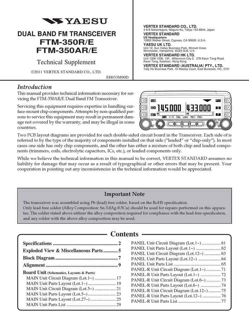
Introduction
This manual provides the technical information necessary for
servicing the FT-60R VHF/UHF Dual Band Transceiver.
Servicing this equipment requires expertise in handing sur-
face-mount chip components. Attempts by non-qualified per-
sons to service this equipment may result in permanent dam-
age not covered by the warranty, and may be illegal in some
countries.
Two PCB layout diagrams are provided for each double-sided
board in this transceiver. Each side of the board is referred to
by the type of the majority of components installed on that
side (“Side A” or “Side B”). In most cases one side has only
chip components (surface-mount devices), and the other has
either a mixture of both chip and leaded components (trim-
mers, coils, electrolytic capacitors, ICs, etc.), or leaded compo-
nents only.
While we believe the information in this manual to be correct,
VERTEX STANDARD assumes no liability for damage that
may occur as a result of typographical or other errors that may
be present. Your cooperation in pointing out any inconsisten-
cies in the technical information would be appreciated.
Contents
VERTEX STANDARD CO., LTD.
4-8-8 Nakameguro, Meguro-Ku, Tokyo 153-8644, Japan
VERTEX STANDARD
US Headquarters
10900 Walker Street, Cypress, CA 90630, U.S.A.
International Division
8350 N.W. 52nd Terrace, Suite 201, Miami, FL 33166, U.S.A.
YAESU EUROPE B.V.
P.O. Box 75525, 1118 ZN Schiphol, The Netherlands
YAESU UK LTD.
Unit 12, Sun Valley Business Park, Winnall Close
Winchester, Hampshire, SO23 0LB, U.K.
VERTEX STANDARD HK LTD.
Unit 5, 20/F., Seaview Centre, 139-141 Hoi Bun Road,
Kwun Tong, Kowloon, Hong Kong
FT-60R
2
pecifications
eneral
quency Ranges: RX 108 - 137 MHz (Air Band),
llular Blocked) 137 - 520 MHz (AM/FM),
700 - 999.990 MHz (FM)
TX 144-148 MHz, 430-450 MHz
annel Steps: 5/10/12.5/15/20/25/50/100 kHz
quency Stability: ±5 ppm @ 14 °F to 140 °F (–10 °C to +60 °C)
peater Shift: ±600 kHz (144 MHz), ±1.6/5.0/7.6 MHz (430 MHz)
ission Type: F2 (F2D), F3 (F3E)
Antenna Impedance: 50 W
Supply Voltage: Nominal: 7.2 V DC, Negative Ground
(Negative Ground) Operating: 6.0 ~ 16.0 V DC (EXT DC Jack)
11.0 ~ 16.0 V DC (EXT DC Jack with Charging)
Current Consumption: 125 mA (Receive)
(Approx. @7.2 V) 45 mA (144 MHz, Standby, Saver Off)
47 mA (430 MHz, Standby, Saver Off)
19 mA (Standby, Saver On)
0.8 mA (Auto Power Off)
1.5 A (5 W TX, 144 MHz)
1.6 A (5 W TX, 430 MHz)
Operating Temperature: –4 °F to 140 °F (–20 °C to +60 °C)
Case Size: 2.3” (W) x 4.3” (H) x 1.2” (D) (58 x 109 x 30 mm) (W/O knob, antenna, and belt clip)
Weight: 13.05 Oz (370 g) with FNB-83, and antenna
Transmitter
RF Power Output: 5.0 W (High) / 2.0 W (Middle) / 0.5 W (Low) (Approx.)
Modulation Type: Variable Reactance F2 (F2D), F3 (F3E)
Maximum Deviation: ±5.0 kHz (F2D, F3E)
Spurious Emission: At least 60 dB down (@ High and Middle power)
At least 40 dB down (@ Low power)
Microphone Impedance:2kW
Receiver
Circuit Type: Double-Conversion Superheterodyne
Intermediate Frequencies: 1st: 47.25 MHz, 2nd: 450 kHz
Sensitivity : 0.8 µV TYP for 10 dB SN (108-137 MHz, AM)
(Cellular Blocked) 0.2 µV for 12 dB SINAD (137-140 MHz, FM)
0.16 µV for 12 dB SINAD (140-150 MHz, FM)
0.2 µV for 12 dB SINAD (150-174 MHz, FM)
0.3 µV TYP for 12 dB SINAD (174-300 MHz, FM)
0.8 µV for 10 dB SN (300-336 MHz, AM)
0.25 µV for 12 dB SINAD (336-420 MHz, FM)
0.2 µV for 12 dB SINAD (400-470 MHz, FM)
0.25 µV for 12 dB SINAD (470-520 MHz, FM)
0.5 µV TYP for 12 dB SINAD (800-900 MHz, FM)
0.8 µV TYP for 12 dB SINAD (800-999.990 MHz, FM)
Selectivity: 12 kHz/35 kHz (–6 dB /–60 dB)
AF Output: 400 mW @ 8 W for 10 % THD (@ 7.5 V)
Specifications are subject to change without notice, and are guaranteed within the 144 and 430 MHz amateur bands only.
Frequency ranges will vary according to transceiver version; check with your dealer.
3
Exploded View & Miscellaneous Par
Screw List
RA0321900
RUBBER CAP
RA0611600
WINDOW
RA0210600
RUBBER PACKING
(x2 pcs)
RA0209900
KNOB
RA0209800
KNOB
RA0209700
VOLUME KNOB
G6090160
LCD
RA0322000
RUBBER
RA032090B
LCD HOLDER
RA0324700
INTER CONNECTOR
RA0324800
REFLECTOR SHEET
RA0211200
INTER CONNECTOR
RA0107000
TERMINAL PLATE R
(x2 pcs)
VR Unit
RA0595200
HOLDER
RA0322800
TERMINAL PLATE
RA0110200
HOLDER RUBBER
CP7970001
BELT CLIP ASSY
RA0613500
RUBBER KNOB
RA0599500
FRONT CASE ASSY
(W/ MIC SHEET,
PACKING PAD(YER),
SP NET,LIGHT GUIDE
DOUBLE FACE(WINDO
RA021020A
RUBBER PACKING
RA0111400
RING NUT (x2 pcs)
RA021080A (Lot. 5 )
SPACER
RA0210800 (Lot. 1 4)
SPACER
RA0318700
BLIND SHEET
CP7969001
REAR CASE ASSY
(W/ SMA CNNECTOR)
M4090142B
SPEAKER
RA055770B (Lot. 31 )
LATCH NAIL C
RA0123500 (Lot. 1 30)
LATCH NAIL B
CAUTION
The mic element must be desoldered and
removed from the PCB on order to rein
stall its protective rubber cover.
Therefore, be careful
not to remove this
cover unless mic ele
ment replacement is
necessary.

Non-designated parts are available only as part of
a designated assembly.
Qty.
14
2
2
2
VXSTD P/N
U9900068
U9900063
U9900051
U02206007
No.




Description
TAPTITE SCREW M2X4NI#3
TAPTITE SCREW 2X3.3NI
TAPTITE SCREW M2X4B#3
SEMS SCREW SM2.6X6B















RA0616500
SPONGE RUBBER
CP7968001
PANEL ASSY
RA0618700
PAD (x2 pcs)
MAIN Unit

Other manuals for FT-60R

7

Other Yaesu Transceiver manuals

Yaesu FT-8800R User manual

Yaesu

Yaesu FT-8800R User manual

Yaesu FTM-300DR User manual

Yaesu

Yaesu FTM-300DR User manual

Yaesu FT-7800R User manual

Yaesu

Yaesu FT-7800R User manual

Yaesu FT2DR User manual

Yaesu

Yaesu FT2DR User manual

Yaesu FT-2900R User manual

Yaesu

Yaesu FT-2900R User manual

Yaesu FTM-400XDR User manual

Yaesu

Yaesu FTM-400XDR User manual

Yaesu FTA-230 User manual

Yaesu

Yaesu FTA-230 User manual

Yaesu VX-3R Manual

Yaesu

Yaesu VX-3R Manual

Yaesu FT-950 Technical manual

Yaesu

Yaesu FT-950 Technical manual

Yaesu FTDX1200 Series Manual

Yaesu

Yaesu FTDX1200 Series Manual

Yaesu FTDX101D User manual

Yaesu

Yaesu FTDX101D User manual

Yaesu FTM-100DR User manual

Yaesu

Yaesu FTM-100DR User manual

Yaesu FT DX 1200 User manual

Yaesu

Yaesu FT DX 1200 User manual

Yaesu FT-8100R Manual

Yaesu

Yaesu FT-8100R Manual

Yaesu VX-6R User manual

Yaesu

Yaesu VX-6R User manual

Yaesu FV-901DM User manual

Yaesu

Yaesu FV-901DM User manual

Yaesu FT-757GX II User manual

Yaesu

Yaesu FT-757GX II User manual

Yaesu FTDX101D User manual

Yaesu

Yaesu FTDX101D User manual

Yaesu FT-8900R User manual

Yaesu

Yaesu FT-8900R User manual

Yaesu FT-857 series Manual

Yaesu

Yaesu FT-857 series Manual

Yaesu FT-230R User manual

Yaesu

Yaesu FT-230R User manual

Yaesu FTdx3000 Series Manual

Yaesu

Yaesu FTdx3000 Series Manual

Yaesu VX-8GR User manual

Yaesu

Yaesu VX-8GR User manual

Yaesu FT-990 User manual

Yaesu

Yaesu FT-990 User manual

Popular Transceiver manuals by other brands

Albrecht DB 275 Dualband manual

Albrecht

Albrecht DB 275 Dualband manual

Super Star 120 owner's manual

Super Star

Super Star 120 owner's manual

Shenzhen GD230B instruction manual

Shenzhen

Shenzhen GD230B instruction manual

Vertex Standard VXA-220 operating manual

Vertex Standard

Vertex Standard VXA-220 operating manual

Vertex FT-817 Technical supplement

Vertex

Vertex FT-817 Technical supplement

Vertex Standard VX-230 Series Service manual

Vertex Standard

Vertex Standard VX-230 Series Service manual

BRONDI FX-300 TWIN PMR 446 instruction manual

BRONDI

BRONDI FX-300 TWIN PMR 446 instruction manual

DRAKE ML-2 instruction manual

DRAKE

DRAKE ML-2 instruction manual

Sumitomo NEOMOTE WM-Z1110 operating manual

Sumitomo

Sumitomo NEOMOTE WM-Z1110 operating manual

Micrel KSZ9031RNX user guide

Micrel

Micrel KSZ9031RNX user guide

Wouxun KG-V55 user manual

Wouxun

Wouxun KG-V55 user manual

Analog Devices AFDF7021 Application note

Analog Devices

Analog Devices AFDF7021 Application note

Radio Shack BTX-128 owner's manual

Radio Shack

Radio Shack BTX-128 owner's manual

nLight Sensor Switch instructions

nLight

nLight Sensor Switch instructions

Icom IC-706MKIIG Service manual

Icom

Icom IC-706MKIIG Service manual

Midland M24 Plus manual

Midland

Midland M24 Plus manual

Kirisun PT578 instruction manual

Kirisun

Kirisun PT578 instruction manual

IRTrans WiFi Hardware guide

IRTrans

IRTrans WiFi Hardware guide

manuals.online logo
manuals.online logoBrands
  • About & Mission
  • Contact us
  • Privacy Policy
  • Terms and Conditions

Copyright 2025 Manuals.Online. All Rights Reserved.