3
3. Preparations before Operation
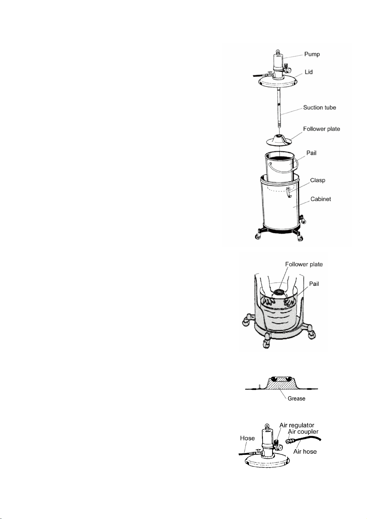
3.1 Setting a Pail(Fig. 1)
1) Release the 3 clasps on the top of the cabinet upward, and
the lid can be removed together with the pump.
2) Take out the follower plate in the cabinet.
<Note>
Take extreme care not to allow sand and dust to adhere on
the suction tube and follower plate of the pump Ass’y.
3) Prepare a new pail and remove its lid. Then, set the can in
the middle of the cabinet.
4) Set the attached follower plate on the top surface of the
grease in the set pail. (For the direction of the follower plate,
refer to Fig. 1.)
5) Place the follower plate on the grease horizontally and push
it down by rubbing it with a hand until the grease comes out
from the packing in the middle of the plate. (Fig. 2)
<Note>
When using the follower plate for the first time after
purchasing the product, pack grease beforehand in the
rear-side concave portion of the plate. This facilitates the
work. (Fig. 3)
6) Insert the suction tube in the pail so that the suction tube of
the pump Ass’y may pass in the middle of the follower plate,
put the lid on the cabinet, and fix the cabinet and the lid with
the 3 clasps.
<Note>
Take care not to blemish the packing of the follower plate by
the end of the suction tube.
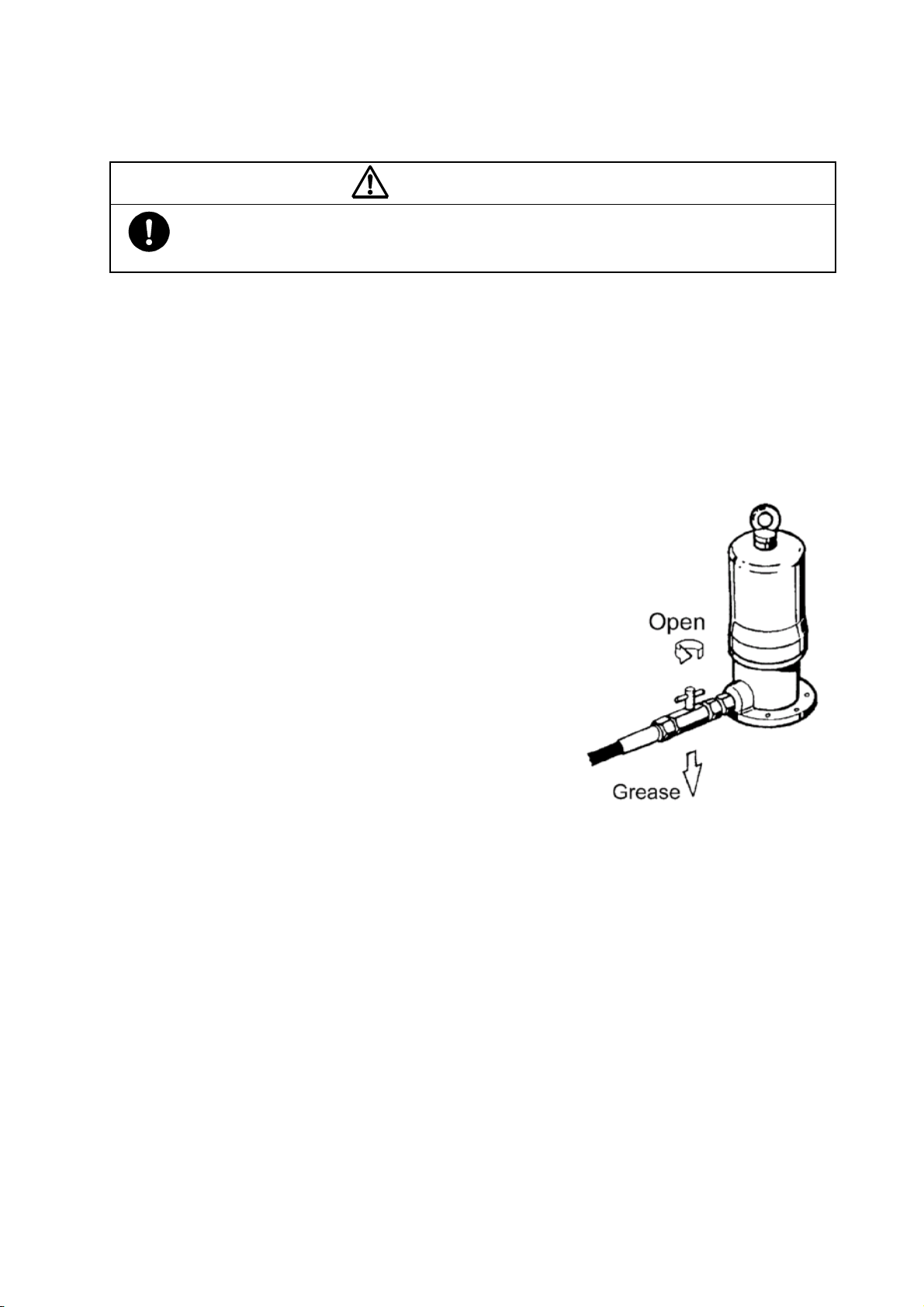
3.2 Assembling the Equipment
1) Install the attached high-pressure hose and the
high-pressure grease gun at the discharge port of the pump,
and then install the air regulator at the air supply port.
Clamp the connecting portion securely. (Fig. 4)
2) Install the attached air chuck on the air hose (for size 1/4,
separately available), and fix it with a hose band.
If the connecting air chuck for the compressor side is not
available, purchase it separately.
Fig. 3
Fig. 2
Fig. 1
Fig. 4