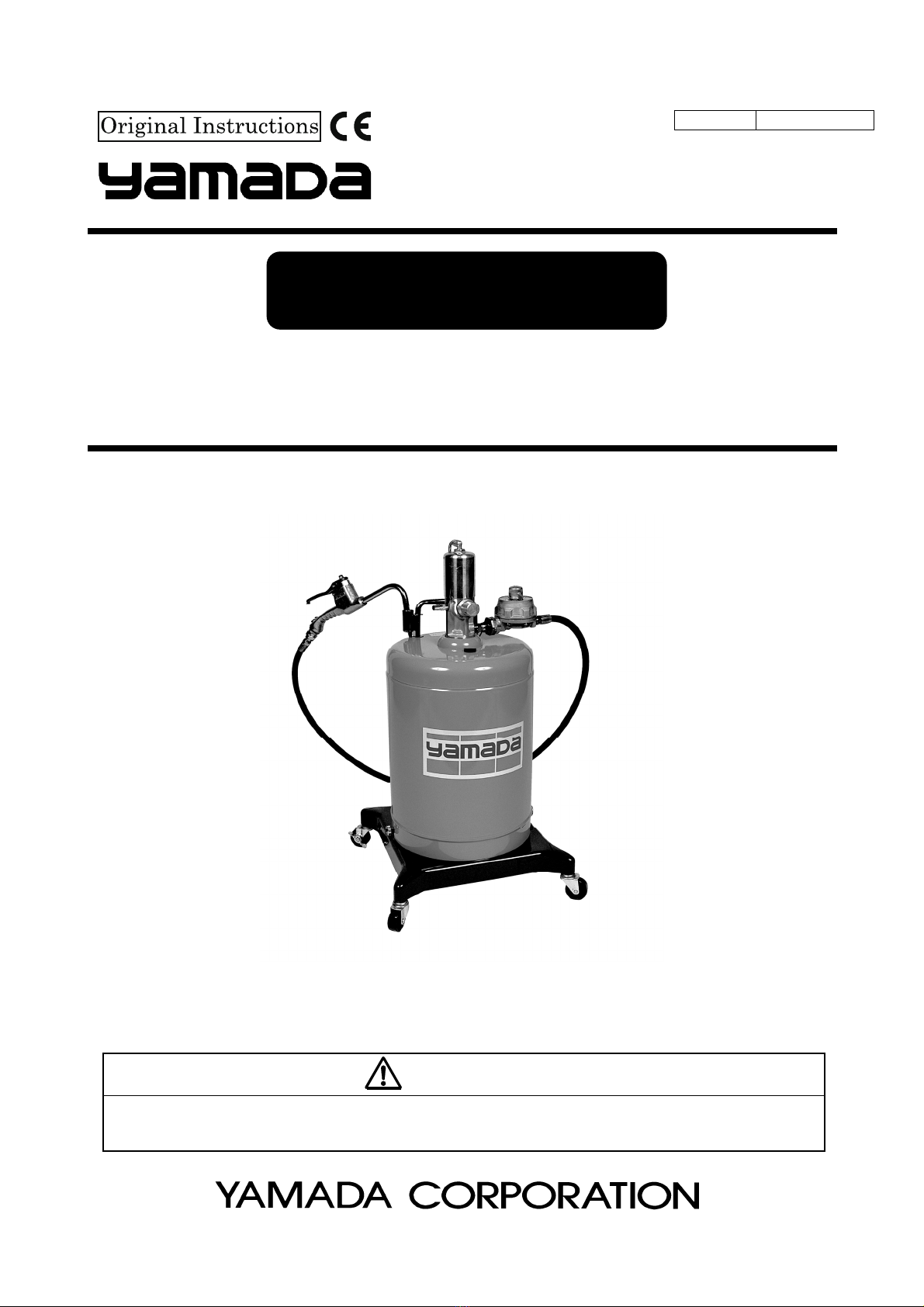
YAMADA SGR-55 880267 User manual

Doc. No. OSA 013U-03
OIL LUBRICATOR
SGR-55 MODEL No.880267
WARNING
Prior to operating this pump, be sure to read this operation manual for safety. After reading the manual, please
keep it at hand any time for your quick reference.
INSTRUCTION

1/3
- Preface
Thank you for purchasing a Yamada Pump. This machine is a portable type oil lubricator to supply lubricant to
machines and vehicles. The machine is provided with a 65 type air-powered pump on the cabinet with a capacity of
20 L, which is suitable to supply of oil.
The machine is also provided with a flow meter in the standard specification, which permits grasp the oil supply
volume accurately.
<Note>
This machine, which is designed exclusively for oil, cannot be used for any substance other than lubricant.
- For Safe Operation
This manual describes the items that are important for the user to operate this product safely, correctly, and efficiently.
Before operating this product, read this manual thoroughly, in particular, “Warnings and Cautions” at the beginning of
this manual.
- Warnings and Cautions
For safe use of this product, be sure to note the following: In this document, warnings and cautions are indicated by
symbols. These symbols are for those who will operate this product and for those who will be nearby, for safe
operation and for prevention of personal injury and property damage. The following warning and caution symbols
have the meanings described below. Be sure to remember their meanings.
WARNING : This indicates the existence of potential hazard which, if not avoided, will
result in death or serious injury.
CAUTION : This indicates the existence of potential hazard which, if not avoided, may
result in bodily injury or in physical damage.
Furthermore, to indicate the type of danger and damage, the following symbols are also used along with those
mentioned above:
This symbol indicates a DON'T, and will be accompanied by an explanation on something you must not
do.
This symbol indicates a DO, and will be accompanied by instructions on something you must do in a
certain situation.

2/3
- Precautions on Use
The following warnings and cautions are very important. Be sure to observe them.
WARNING
- The operator and maintenance engineer should read the operation manual thoroughly before operating
this product and performing maintenance in respect of this product.
- Always wear proper safety equipments (facemask, ear plugs, and safety shoes, etc.) when installing,
operating and disassembling this product.
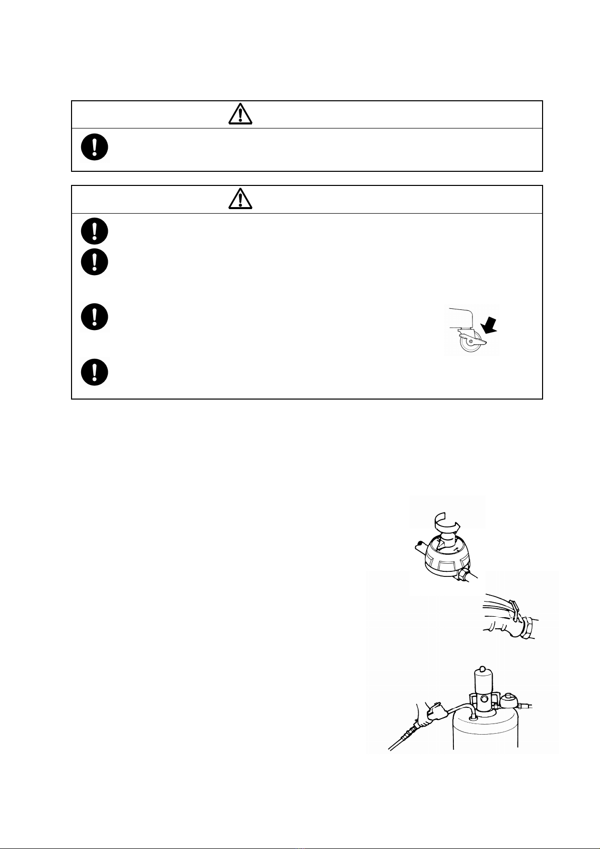
- Lock caster's stopper during and after the work, so that this product should not move unexpectedly.
Also, do not use or leave this product in a slope or any unstable locations. This product moves freely
when the caster is not locked and the damage only accident and the facilities pollution, etc. might occur.
Such a secondary disaster becomes a responsibility on the user side.
- Make ground connection when working with flammable material or in explosive atmosphere. Rapid
pumping of material can result in static electrical charge.
Also, be sure to provide proper ventilation where a flammable atmosphere may exist.
- Execute the daily checkup.
- Use this product according to the product specification.
- Attach a valve (for stop in emergency) or regulator to the air supply pipe to keep supply air pressure
under 0.7MPa.
- Be careful not to drop the cabinet when lifting it up to replace a pail. Catching a falling cabinet may
cause hand injury by its edge.
- Make sure the valve of the oil gun is closed before running the pump. Operating with the valve open
can cause a hose runaway.
- Discontinue it when you feel a hazard or abnormality during the work. And correspond according to the
troubleshooting.
- Keep your face away from the exhaust and discharge ports. Material may suddenly come out. There is
a possibility of losing eyesight if it strikes eyes.
- Stop pump operation immediately when a drum becomes empty. Running the pump dry will cause
excessive vibration, resulting in reduction of pump life and damage to other equipment.
- Be very careful not to drop the grease gun. It may become damaged, resulting in leakage and
malfunction.
- Do not aim exhalation part of this product at any person. Residual pressure may be left inside the gun
even when the pump is not in operation. There is a possibility of losing eyesight if it strikes eyes.
- Before maintenance operation, be sure to stop air from being supplied to the pump, and release the
internal pressure (both air and material) of the pump. There is danger such as spouting of the material
when the maintenance work is done with air supplied.
- Gasoline is a high volatile fuel. Do not use it to clean the pump in any case, otherwise ignition or
explosion may be caused.
- Modification of this pump may lead to death, bodily injury, or a failure. Do not modify it in any case
because it involves a risk.
- Do not discharge material directly onto the ground. Dispose of harmful materials according to the
requirements specified in MSDS or local regulations. Also, dispose of this product according to the local
regulations after removing residual material from inside this product. (Please contact industrial waste
disposal service.)

3/3
CAUTION
- Use this product for the material suitable for the specification. Parts may be corroded and material leak
from the damaged parts can lead to environmental pollution. Also, follow handling notes (MSDS) of the
manufacturer about the handling of the material used.
- Move this product slowly and carefully. Avoid any sudden movements like sudden start, stop, and turn.
Material in this product may spill out.
- Take protective measures against rainwater and dust. It is likely to lead to the pollution of the material.
- Watch your step around this product to avoid tripping over the base and casters.
- Be careful about your hands when mounting/dismounting the cabinet or installing a pail. The edges of
the cabinet and pail may cause hand injury. Also, be careful about your posture when moving the pump
or lifting the cabinet to avoid back injury.
- Material remaining inside or on the surface of the pump may spill out by inserting or removing the pump
into/from a pail. Be very careful not to get your clothing dirty.
- Keep hands and fingers away from this product during operation to avoid injury from moving parts.
- Do not touch the surfaces of the pump and the hose when pumping high-temperature material. Risk of
burns exists.
- Be careful when handling the grease gun. Avoid finger injury from being caught between the lever and
gun. The finger might be injured.
- Stop the air supply source after the end of work when not using this pump for a long time such as
nighttimes and holidays. Also, open the valve of the exhalation port and liberate pressure in the pump
and the hose. There is a possibility of polluting facilities because of the damage of the hose and the
leakage of the valve. Such a secondary disaster becomes a responsibility on the user side.

Table of Contents
- Preface
- For Safe Operation
- Warnings and Cautions
- Precautions on Use
1. Names and Materials of Parts
1.1 Names and Materials of Parts ............................................................................................. 1
1.2 Contents of Package ........................................................................................................... 1
2. Principle of Operation
2.1 Function of the Air Motor ..................................................................................................... 2
2.2 Function of the Lower Pump................................................................................................ 2
3. Preparations before Operation ........................................................................................... 3
4. How to Operate the Machine ............................................................................................... 4
5. Maintenance and Inspection
5.1 Troubleshooting and Corrective Measures .......................................................................... 5
5.2 Maintenance and Inspection................................................................................................ 6
6. Disassembly and Assembly................................................................................................. 6
7. Parts Disassembly Drawing and Parts List
7.1 880267 SGR-55................................................................................................................... 8
7.2 850206 Oil Gun Ass’y .......................................................................................................... 8
7.3 850792 Pump Ass’y............................................................................................................. 9
8. Specification............................................................................................................................ 10
9. Limited Warranty .................................................................................................................... 11

1
1. Names and Materials of Parts
1.1 Names and Materials of Parts
1.2 Contents of Package
The main equipment and accessories are packed in different cases. Open the top part of the corrugated fiberboard
case and check if the pump assembly and oil can are not damaged and if accessories are all contained in the
package.

2
2. Principle of Operation
The YAMADA Air-powered Pump is a reciprocating type pump that is driven by compressed air. This pump consists
of an air motor to drive the pump and a lower pump to draw up the liquid material as shown in the figure.
2.1 Function of the Air Motor
1) In the status shown in the figure at right, the air piston reaches the
upper limit and is now about to go down.
2) The compressed air fed from the air supply port is applied to the
chamber A through the air passage tube from the path provided in
the lower part of the slide valve. The air pressure of the chamber
B is discharged out through the slide valve.
3) As a result, the air piston starts to go down.
4) When the air piston collides with the trip shoe, the slide valve is
momentarily tripped downward by the function of the trip
mechanism.
5) As a result, the air supply is conducted to the chamber B and the
chamber A is conducted to the exhaust port, so that the air piston
is changed to go up.
6) Thus, the air motor continues its reciprocating motion
automatically as long as the supply air is fed to it.
2.2 Function of the Lower Pump
1) The lower pump integrated with the air motor traces the
reciprocating motion of the air motor.
2) This reciprocating motion of the piston causes a sucking operation
and a compressive operation to the suction valve and the piston
valve of the lower pump, thereby discharging the liquid
intermittently.
3) This reciprocating motion is automatically continued until the
delivery side is closed and the liquid compressive pressure of the
lower pump is balanced with the pressure of the air motor.

3
3. Preparations before Operation
1) First loosen the pan-head screw and take out the pump from
the cabinet.
Remove the rubber cap at the bottom of the pump Ass’y, insert
the pump into the cabinet, and fix it with a pan-head screw.
Refer to <Assembly of Equipment> indicated on the top
surface of the corrugated fiberboard case. (Fig.1)
2) Loosen the two clamping nuts at the bottom of the cabinet
(turn them counterclockwise), and remove the cabinet from the
base frame. (Fig.2)
3) Transfer the oil to the exclusive use oil can. (Fig.2)
4) Place a oil can in the middle of the base frame and install the
cabinet as it was. Tighten the clamping nut on both sides
equally. (Fig.2)
5) Install the attached hose and the gun at the oil discharge port
of the pump, and clamp the connecting portion securely.
6) Connect the attached air coupler to the air hose and fix it with
a hose band. (The air hose is separately available.) If the air
coupler to be connected to the compressor is not available,
purchase it separately.
7) When the air coupler is connected to the pump, the pump will
be operated for a while, and the pump and hose will be filled with oil.
After that, the pump operation will stop. If the gun lever is pulled in
this status, the oil lubricator can be used any time.
<Note>
- Install the air regulator (separately available) at the air supply port
of the pump. The dedicated air regulator is available as the
standard product. Please use it
- Using the air regulator permits adjusting the supply air pressure to
the pump and reducing the wasteful motion of the pump, with the
result that the operability is improved and the pump life is extended.
In the normal operating status, the pointer of the pressure gauge
should be at 0.3 to 0.5 MPa.

4
Fig. 3
Fig. 4a
Fig. 4b
Fig. 5
4. How to Operate the Machine
WARNING
- When the machine is operated, electrostatic sparks may give a shock to the human body or cause
death or bodily injury due to a fire or explosion. Be sure to perform grounding securely by using a
grounding conductor according to the operating environment.
CAUTION
- The supply air pressure should be 0.7 MPa or less. If the primary pressure is more than 0.7 MPa,
install an air regulator on the air line and adjust the pressure to 0.7 MPa or less.
- After the end of daily work or when the machine is not operated for a long time, be sure to shut off the
supply air and open the discharge port valve to bleed the internal pressure of the pump and hose. Any
secondary accident such as pollution of installation, due to hose damage or leakage from the valve
without shutting off the supply air, shall be attributable to the user’s responsibility.
- During machine operation or after completion of movement, be sure to lock
the caster brake for locking. A turnover of equipment may pollute the
installation. (Fig.3)
- During oil change, take extreme care not to allow sand and dust to adhere on the suction tune of the
pump. If sand is mixed in the oil, it will give breakage to the pump and also damage to the important
machine.
<Note>
Using the air regulator permits adjusting the supply air pressure to the pump and reducing the wasteful motion of
the pump, with the result that the operability is improved and the pump life is extended. In the normal operating
status, the pointer of the pressure gauge should be at 0.3 to 0.5 MPa.
1) First loosen the pan-head screw and take out the pump from Before
starting oil supply, be sure to turn the knob of the oil meter
counterclockwise to reset to the “0” position.(Fig.4a)
2) The pump is operated by pulling the lever of the oil gun, and oil is
discharged. To continuously discharge the oil, hook the lever to the
hardware provided at the gun rear. (Fig.4b)
If the discharge oil pressure is so high as to cause splashes, adjust the
supply air pressure with the air regulator.
3) After completion of oiling work, be sure to shut off the supply air of the
pump and bleed the internal air of the hose. For bleeding the internal
pressure of the pump and hose, Insert the oil gun in the return hole of
the lid and pull the gun lever. (Fig.5)

5
YES
NO
The pump cannot be
operated.
Check if the air regulator
is normally operated.
Check if the valve on the
outlet on the pump side
is not closed.
Remove the lower pump
and operate the air motor
independently.
Check if the valve in the
course of piping is not
closed.
Clogging occurs in the
connecting hose, pipe,
outlet valve, or gun.
The lower pump is faulty.
The packing seal of the
air motor is worn away.
Ask for servicing the
lower pump and see
P. 7 .
The pump is
continuously
operated without
stop.
Check if there is any
open valve on the
material output side.
Check if the material
does not leak at the
exhaust port of the air
motor.
The air motor is fault
y
.
Ask for servicing the
air motor
When the outlet side is
closed, check if any leak
does not occur on the
pipe, connecting hose or
its connecting portion.
The valve of the lower
pump or the packing is
worn away.
The pump operated
but the material is
not fed by pressure.
The pump can be
operated but the
discharge volume is
insufficient.
The material vessel is
empty.
Check if the supply air
pressure is not lowered.
Check and re-supply, or
replace.
The air supply volume
to the pump is
insufficient. Replace
the air hose with a
thicker one or check
the air compressor.
check
check
operable
Increase the pressure up
to 0.7MPa by the air
regulator. At this time, the
oil volume does not reach
the specified level.
The valve seat surface of
the lower pump, the
packing is worn away or
clogging is caused by
dust or foreign
substances.
NO
YES
NO
YES
inoperable
YES
NO
5. Maintenance and Inspection
5.1 Troubleshooting and Corrective Measures
If the pump operation becomes unstable or trouble is caused to its oil discharge during operation, make a check
according to the following procedure.
Symptom Cause Contents of inspection and corrective measures

6
Fig. 6
Fig. 7
5.2 Maintenance and Inspection
[Oiling]
For lubrication of the pump, perform oiling once every 10 days with lubricating oil. (Fig.6)
Supply the lubricating oil as following.
1) Remove the air regulator.
2) Inject a few drops of lubricating oil (approx. 0.5 ml) into the air supply port as shown in
the figure at right.
Use turbine oil class 1 ISO (VG-32) or equivalent as the lubricating oil.
[Inspection]
1) Oil is a fluid and easily polluted. Keep it clean at all times.
2) To protect the oil meter, a filter is installed between the pump and
the oil gun. If filter clogging occurs, the oil flow is get worse. Clean
the filter sometimes. (Fig.7)
3) The oil-proof hose is a consumable product. Check it periodically.
If any blemish or leakage is found, replace the hose a little earlier.
4) The packing of the pump will be worn away. Check and replace it
at least once a year.
6. Disassembly and Assembly
When the pump operation becomes defective or stops, do not disassemble the pump thoughtlessly but refer to the
item on P.5 (Troubleshooting and Corrective Measures), and judge the condition carefully and disassemble only the
minimum necessary parts.
The air motor is rarely touched directly, so its failure rate is very low. The air motor does not need to be disassembled.
If disassembling is required, ask the dealer to disassemble the air motor.
WARNING
- Gasoline is a high-volatility material. Do not use gasoline to clean the pump in any case, otherwise it
may cause ignition or explosion.
CAUTION
- Before starting disassembling or inspecting the machine, be sure to shut off the supply air and open
the outlet valve to release the internal pressure of the machine.
- When washing parts, do not use such a liquid as corrodes aluminum, copper alloy, iron, etc.

7
Fig. 8
Fig. 10
Fig. 9
[Disassembling the air motor and the lower pump]
1) Shut off the air that is supplied to the pump to release the internal
pressure of the pump.
2) Disconnect the air connection hose, material hose, etc. from the pump.
3) Unscrew the pan-head screw of the body supporter that fixes the pump.
Pull out the pump upward, and the pump can be removed from the
cabinet.(Fig.8)
4) Fix the air motor body of the pump on a vise. (Fig.9)
<Note>
The air cylinder is easily damaged. Do not fix it on the vise in any case.
5) Set a pipe wrench on the knurling part of the suction tube and unscrew the
suction tube to remove the suction tube. (Fig.9)
6) Pull out the pin of the piston rod and unscrew the connecting rod to
remove it. Then, the air motor and the lower pump can be separated from
each other.
[Disassembling the lower pump]
1) Disconnecting the piston rod of the air motor from the connecting rod by
removing the pin. (Fig.10)
2) The ball, cap-packing, spring, etc. can be disassembled by unscrewing the
valve seat with the housing of the intake valve ass’y secure. Wash and
check each part. Replace the worn parts, if any. (Fig.11)
[Disassembling the air motor]
-The air motor is not easily adjusted at assembly. If an air motor
failure is found at maintenance and inspection, ask the dealer to
repair the air motor.
-For the user who intends to perform maintenance, the manual
related to the disassembly and structure of the motor is available
as a separate volume.
Ask the dealer for further information.
Fig. 11

8
7. Parts Disassembly Drawing and Parts List
7.1 880267 SGR-55
7.2 850206 Oil Gun Ass’y
No. Parts No. Descriptions Q’ty
1 850792 Pump Ass’y 1
2 680743 Air coupler (plug) 1
3 802538 Filter 1
4 802570 Oil meter 1
5 695052 Hose 1
6 850206 Oil gun 1
7 830138 Gun holder 1
8 705841 Handle 1
9 770754 Return 1
10 682276 Nut with flange 2
11 830800 Cabinet 1
12 602296 Pan-head screw 1
13 682905 Oil can 1
14 704570 Clamping nut 2
15 831098 Base frame 1
16 681767 Caster(with brake) 2
17 680136 Caster 2
18 681769 Grounding conductor 1
19 685370 Union adapter 1
No. Parts No. Descriptions Q’ty
1 627290 Nut 2
2 703095 Handle 1
3 703097 Link 1
4 703096 Pin 1
5 703098 Pin 1
6 630777 E-stop ring 4
7 703089 Packing holder 1
8 640019 O-ring 1
9 680275 Packing 1
10 703090 Washer 1
11 707378 Spring 1
12 703094 Spring holder 1
13 703093 Spring 1
14 703088 Valve stem 1
15 770319 Packing 1
16 795021 Valve 1
17 703100 Valve seat 1
18 703101 Washer 1
19 703091 Body 1
20 703099 Handle hanger 1
21 703323 Union 1
22 630316 Ball 1
23 703322 Spring 1
24 703324 Nozzle 1
25 703321 Nozzle pipe 1
26 703328 Swivel nut 1
27 703327 Swivel stud 1
28 640014 O-ring 1
29 703329 Swivel body 1
No.1~20: 800683 Valve body Ass’y
No.21~25 : 800680 Nozzle Ass’y
No.26~29 : 800684 Swivel joint Ass’y

9
7.3 850792 Pump Ass’y
<Note>
If an air motor failure is found at maintenance and inspection, ask the dealer to repair the air motor.
No. Parts No. Descriptions Q’ty No. Parts No. Descriptions Q’ty
1 701768 Elbow 2 24 701825 Spring 1
2 701765 Tube sleeve 2 25 682976 O-ring 1
3 701766 Tube gland 2 26 710672 Spring cover 1
4 708523 Air passage tube 1 27 706068 Piston rod 1
5 708311 Air cylinder bonnet 1 28 702725 Washer 1
6 701811 Cap nut 1 29 770287 Gland packing 4
7 701815 Plate 2 30 702726 Packing retainer 1
8 770180 Piston packing 1 31 702727 Spring 1
9 701810 Washer 1 32 704297 Washer 1
10 706067 Spindle bush 1 33 703010 Suction tube 1
11 640012 O-ring 1 34 706091 Union 1
12 706066 Gland housing 1 35 632039 Pin 2
13 770182 O-ring 1 36 703011 Connecting rod 1
14 706077 Air motor body 1 37 632039 Pin 1
15 770181 Valve seat gasket 1 38 702772 Valve housing 1
16 701822 Valve seat 1 39 702773 Washer 1
17 590085 Valve guide plate 1 40 770292 Cap-packing 1
18 701823 Valve slide 1 41 702774 Washer 1
19 701816 Valve supporter 1 42 702776 Spring 1
20 705659 Trip shoe 1 43 630324 Ball 1
21 681768 Screw (w/spring) 2 44 702775 Valve seat 1
22 705661 Trip shoe guide 1 45 803484 Foot valve ass’y 1
23 704893 Spring holder 1
Air Motor Lower Pump

10
8. Specification
■Specification
■Performance Curve (only the pump)
<Note>
The continuous pump operation should be
avoided if the desired delivery is in the range
shaded in the figure below.
■Dimensions
SGR-55
880267
1.8 x 1
FLUID CONNECTION DISCHARGE PORT Oil gun
AIR CONNECTION SUPPLY PORT Coupler plug,PS-20PM
0.2 ~ 0.7 MPa
A-WEIGHTED SOUND
PRESSURE LEVEL *1 86 dB
A-WEIGHTED SOUND
POWER LEVEL *2 96 dB
ENV. TEMPERATURE 0 ~ 60 ℃
MATERIAL TEMP. 0 ~ 80 ℃
16.0 kg
Hose (695052) 3/8×1.5m
Oil gun (850206)
Oil meter (802570) 3~10 L/min
Oil can (682905) 20 L
Air coupler (680743)
*1 Measurement method of A-weighted sound pressure level is based on ISO 1996.
*2 Measurement method of A-weighted sound power level is based on ISO 3744.
TYPE
MODEL No.
PUMP RATIO (NOMINAL)
OPERATING AIR PRESSURE
WEIGHT
AMB. TEMP. RANGE
ACCESSORIES
MAXIMUM
OPERATING NOISE

11
9. Limited Warranty
●If an abnormality occurs during normal operation in accordance with the operating instructions and other operating
cautions within the warranty period (12 months after date of purchase) that can be attributed to a manufacturing
defect, the defective parts of this product will be serviced or the product will be replaced free of charge. However,
this warranty will not cover compensation for incidental damage or any malfunction listed below.
1. Warranty period
This warranty will be valid for a period of 12 months after the date of purchase.
2. Warranty
If, during the warranty period, any of the material of the genuine parts of this product or the workmanship of this
product is found defective, and is so verified by our company, the servicing cost will be fully born by our company.
3. Exclusion
Even during the warranty period, this warranty does not cover the following:
1) Malfunction arising from use of parts other than manufacturer-specified genuine parts
2) Malfunction arising from misuse or operating errors, or lack of storage or maintenance care
3) Malfunction arising from use with a fluid that may cause corrosion, inflation or dissolution of the component
parts of the product
4) Irregularity arising from repair made by other than by our firm, our regional office, dealer or authorized service
personnel
5) Malfunction arising from modification of the product by other than authorized service personnel
6) Wear and tear of parts that must be regularly replaced in the course of normal operation, such as packings,
O-rings, balls, and valve seats
7) Malfunction and/or damage due to transportation, moving or droppage of the product after purchase
8) Malfunction and/or damage due to fire, earthquake, flood or other force majeure
9) Malfunction arising from use of compressed air that contains impurities or excessive moisture, or use of
gases or fluids other than the specified compressed air
10) Malfunction arising from use with a fluid that causes excessive abrasion or use of lubricating oil other than
that specified for this product
Furthermore, this warranty does not cover the rubber parts, or other parts that are subject to wear in normal
operation, used in this product and its accessories.
4. Parts
Parts for this product will be kept available for 5 years after discontinuation of production. Once 5 years have
elapsed after close of production, availability of parts for this product cannot be guaranteed.

MEMO.

201303 OSA013U
Manufactured by
YAMADA
CORPORATION
INTERNATIONAL DEPARTMENT
No.1-3, 1-Chome, Mimami-Magome, Ohta-Ku, Tokyo, 143-8504, Japan
PHONE : +81-(0)3-3777-0241
FAX : +81-(0)3-3777-0584
YAMADA
EUROPE
B.V.
Aquamarijnstraat 50, 7554 NS Hengelo (0), The Netherlands
PHONE : 31(0) 74-2422032
FAX : 31(0) 74-2421055
This manual suits for next models
2
Table of contents
Other YAMADA Lubrication System manuals
Popular Lubrication System manuals by other brands

Lincoln
Lincoln SKF Centro-Matic User and maintenance instructions

iSHAN
iSHAN YGL-G Operation manual

Pulsarlube
Pulsarlube OL500 user manual

GUDEL
GUDEL 404DLS operating manual

Bijur Delimon
Bijur Delimon V5B quick start guide

Lincoln industrial
Lincoln industrial QLS 301 Assembly, installation and operation instructions