YASKAWA VIPA System 300S User manual

SM-DIO | | Manual
HB140 | SM-DIO | | en | Rev. 16-43
VIPA System 300S
Digital signal modules - SM 32x(S)
www.vipa.com/en/service-support/manual

300S_SM-DIO,4,GB - © 2016
VIPA GmbH
Ohmstr. 4
91074 Herzogenaurach
Telephone: 09132-744-0
Fax: 09132-744-1864
Email: [email protected]
Internet: www.vipa.com

Table of contents
1 Basics...................................................................................................................... 5
1.1 Copyright © VIPA GmbH ................................................................................. 5
1.2 About this manual............................................................................................. 6
1.3 Safety information............................................................................................. 7
2 Assembly and installation guidelines.................................................................. 8
2.1 Safety information for users.............................................................................. 8
2.2 Overview........................................................................................................... 9
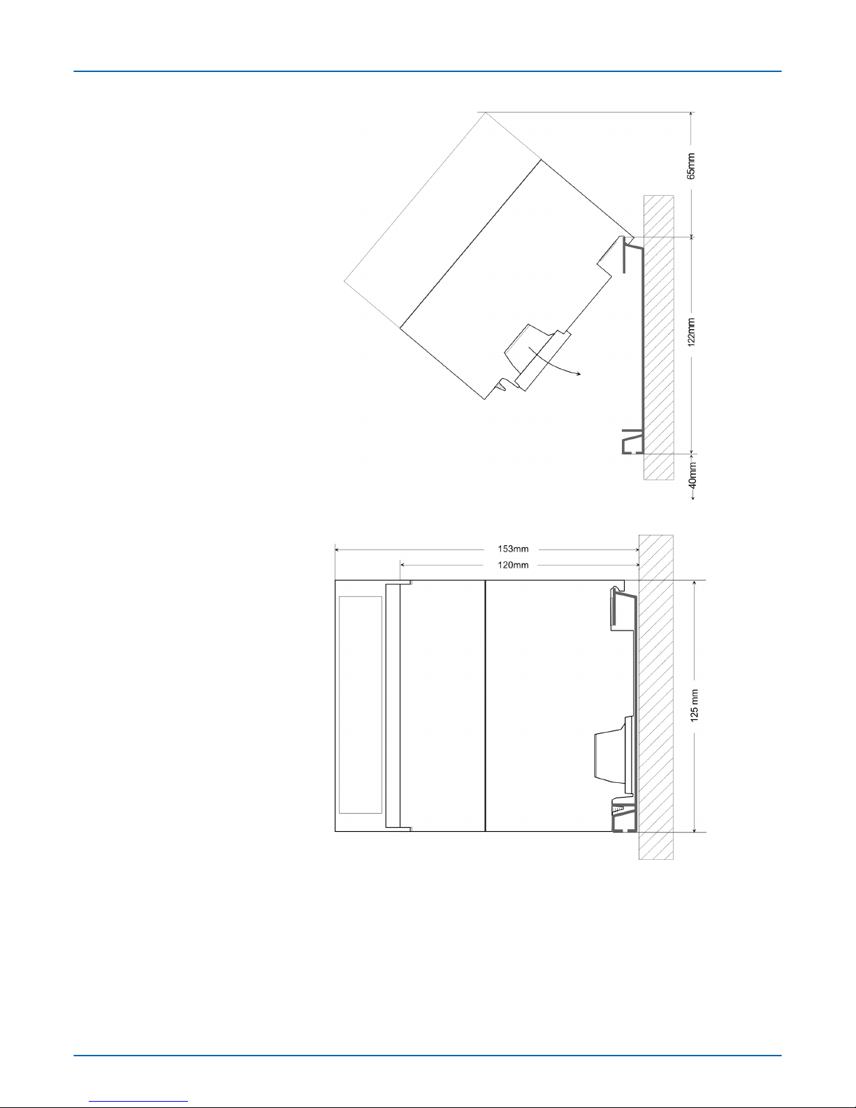
2.3 Installation dimensions..................................................................................... 9
2.4 Assembly SPEED-Bus.................................................................................... 11
2.5 Assembly standard bus.................................................................................. 14
2.6 Cabling........................................................................................................... 16
2.7 Installation guidelines..................................................................................... 19
2.8 General data I/O modules.............................................................................. 21
2.8.1 General data................................................................................................ 22
3 Digital Input Modules........................................................................................... 24
3.1 321-1BH01 - DI 16xDC 24V........................................................................... 24
3.1.1 Technical data.............................................................................................. 25
3.2 321-1BL00 - DI 32xDC 24V............................................................................ 27
3.2.1 Technical data.............................................................................................. 29
3.3 321-1FH00 - DI 16xAC120/230V.................................................................... 31
3.3.1 Technical data.............................................................................................. 33
4 Digital Output Modules........................................................................................ 35
4.1 Safe shutdown of non-safe outputs................................................................ 35
4.1.1 Introduction.................................................................................................. 35
4.1.2 Safe shutdown............................................................................................. 35
4.1.3 Requirements and fault exclusions.............................................................. 36
4.2 322-1BF01 - DO 8xDC 24V 2A...................................................................... 38
4.2.1 Technical data.............................................................................................. 39
4.3 322-1BH01 - DO 16xDC 24V 1A.................................................................... 41
4.3.1 Technical data.............................................................................................. 43
4.4 322-1BH41 - DO 16xDC 24V 2A.................................................................... 45
4.4.1 Technical data.............................................................................................. 48
4.5 322-1BH60 - DO 16xDC 24V 0.5A for manual operation............................... 50
4.5.1 Deployment................................................................................................. 52
4.5.2 Technical data.............................................................................................. 52
4.6 322-1BL00 - DO 32xDC 24V 1A .................................................................... 54
4.6.1 Deployment................................................................................................. 57
4.6.2 Technical data.............................................................................................. 57
4.7 322-5FF00 - DO 8xAC 120/230V 2A ............................................................. 59
4.7.1 Parameterization ........................................................................................ 62
4.7.2 Technical data.............................................................................................. 63
4.8 322-1HH00 - DO 16xRelay ............................................................................ 65
4.8.1 Technical data.............................................................................................. 68
5 Digital Input/Output Modules.............................................................................. 71
5.1 323-1BH00 - DIO 16xDC 24V 1A................................................................... 71
5.1.1 Technical data.............................................................................................. 73
5.2 323-1BH01 - DI 8xDC 24V, DO 8xDC 24V 1A............................................... 75
VIPA System 300S Table of contents
HB140 | SM-DIO | | en | Rev. 16-43 3

5.2.1 Technical data.............................................................................................. 77
5.3 323-1BL00 - DI 16xDC 24V, DO 16xDC 24V 1A............................................ 80
5.3.1 Technical data.............................................................................................. 82
6 Digital Modules FAST - SPEED-Bus................................................................... 85
6.1 Addressing at SPEED-Bus............................................................................. 85
6.2 Project engineering......................................................................................... 85
6.2.1 Fast introduction.......................................................................................... 86
6.2.2 Preconditions............................................................................................... 86
6.2.3 Steps of project engineering........................................................................ 87
6.3 321-1BH70 - DI 16xDC 24V........................................................................... 89
6.3.1 Parameterization......................................................................................... 92
6.3.2 Process interrupt......................................................................................... 96
6.3.3 Diagnostic interrupt...................................................................................... 97
6.3.4 Technical data............................................................................................ 100
6.4 322-1BH70 - DO 16xDC 24V 0.5A............................................................... 102
6.4.1 Technical data............................................................................................ 105
6.5 323-1BH70 - DIO 16xDC 24V 0.5A.............................................................. 106
6.5.1 Parameterization....................................................................................... 109
6.5.2 Process interrupt........................................................................................ 114
6.5.3 Diagnostic interrupt.................................................................................... 114
6.5.4 Technical data............................................................................................ 117
VIPA System 300S
Table of contents
HB140 | SM-DIO | | en | Rev. 16-43 4

1 Basics
1.1 Copyright © VIPA GmbH
This document contains proprietary information of VIPA and is not to be disclosed or used
except in accordance with applicable agreements.
This material is protected by the copyright laws. It may not be reproduced, distributed, or
altered in any fashion by any entity (either internal or external to VIPA), except in accord-
ance with applicable agreements, contracts or licensing, without the express written con-
sent of VIPA and the business management owner of the material.
For permission to reproduce or distribute, please contact: VIPA, Gesellschaft für Visuali-
sierung und Prozessautomatisierung mbH Ohmstraße 4, D-91074 Herzogenaurach, Ger-
many
Tel.: +49 9132 744 -0
Fax.: +49 9132 744-1864
EMail: [email protected]
http://www.vipa.com
Every effort has been made to ensure that the information contained in
this document was complete and accurate at the time of publishing. Nev-
ertheless, the authors retain the right to modify the information.
This customer document describes all the hardware units and functions
known at the present time. Descriptions may be included for units which
are not present at the customer site. The exact scope of delivery is
described in the respective purchase contract.
Hereby, VIPA GmbH declares that the products and systems are in compliance with the
essential requirements and other relevant provisions. Conformity is indicated by the CE
marking affixed to the product.
For more information regarding CE marking and Declaration of Conformity (DoC), please
contact your local VIPA customer service organization.
VIPA, SLIO, System 100V, System 200V, System 300V, System 300S, System 400V,
System 500S and Commander Compact are registered trademarks of VIPA Gesellschaft
für Visualisierung und Prozessautomatisierung mbH.
SPEED7 is a registered trademark of profichip GmbH.
SIMATIC, STEP, SINEC, TIA Portal, S7-300 and S7-400 are registered trademarks of
Siemens AG.
Microsoft and Windows are registered trademarks of Microsoft Inc., USA.
Portable Document Format (PDF) and Postscript are registered trademarks of Adobe
Systems, Inc.
All other trademarks, logos and service or product marks specified herein are owned by
their respective companies.
Contact your local VIPA Customer Service Organization representative if you wish to
report errors or questions regarding the contents of this document. If you are unable to
locate a customer service centre, contact VIPA as follows:
All Rights Reserved
CE Conformity Declaration
Conformity Information
Trademarks
Information product sup-
port
VIPA System 300S Basics
Copyright © VIPA GmbH
HB140 | SM-DIO | | en | Rev. 16-43 5

VIPA GmbH, Ohmstraße 4, 91074 Herzogenaurach, Germany
Telefax: +49 9132 744-1204
EMail: [email protected]
Contact your local VIPA Customer Service Organization representative if you encounter
problems with the product or have questions regarding the product. If you are unable to
locate a customer service centre, contact VIPA as follows:
VIPA GmbH, Ohmstraße 4, 91074 Herzogenaurach, Germany
Tel.: +49 9132 744-1150 (Hotline)
EMail: [email protected]
1.2 About this manual
The manual is targeted at users who have a background in automation technology.
The manual consists of chapters. Every chapter provides a self-contained description of a
specific topic.
The following guides are available in the manual:
nAn overall table of contents at the beginning of the manual
nReferences with page numbers
The manual is available in:
nprinted form, on paper
nin electronic form as PDF-file (Adobe Acrobat Reader)
Important passages in the text are highlighted by following icons and headings:
DANGER!
Immediate or likely danger. Personal injury is possible.
CAUTION!
Damages to property is likely if these warnings are not heeded.
Supplementary information and useful tips.
Technical support
Target audience
Structure of the manual
Guide to the document
Availability
Icons Headings
VIPA System 300S
Basics
About this manual
HB140 | SM-DIO | | en | Rev. 16-43 6

1.3 Safety information
The system is constructed and produced for:
ncommunication and process control
ngeneral control and automation tasks
nindustrial applications
noperation within the environmental conditions specified in the technical data
ninstallation into a cubicle
DANGER!
This device is not certified for applications in
–in explosive environments (EX-zone)
The manual must be available to all personnel in the
nproject design department
ninstallation department
ncommissioning
noperation
CAUTION!
The following conditions must be met before using or commis-
sioning the components described in this manual:
– Hardware modifications to the process control system should only be
carried out when the system has been disconnected from power!
– Installation and hardware modifications only by properly trained per-
sonnel.
– The national rules and regulations of the respective country must be
satisfied (installation, safety, EMC ...)
National rules and regulations apply to the disposal of the unit!
Applications conforming
with specifications
Documentation
Disposal
VIPA System 300S Basics
Safety information
HB140 | SM-DIO | | en | Rev. 16-43 7

2 Assembly and installation guidelines
2.1 Safety information for users
VIPA modules make use of highly integrated components in MOS-Technology. These
components are extremely sensitive to over-voltages that can occur during electrostatic
discharges. The following symbol is attached to modules that can be destroyed by elec-
trostatic discharges.
The Symbol is located on the module, the module rack or on packing material and it indi-
cates the presence of electrostatic sensitive equipment. It is possible that electrostatic
sensitive equipment is destroyed by energies and voltages that are far less than the
human threshold of perception. These voltages can occur where persons do not dis-
charge themselves before handling electrostatic sensitive modules and they can damage
components thereby, causing the module to become inoperable or unusable. Modules
that have been damaged by electrostatic discharges can fail after a temperature change,
mechanical shock or changes in the electrical load. Only the consequent implementation
of protection devices and meticulous attention to the applicable rules and regulations for
handling the respective equipment can prevent failures of electrostatic sensitive modules.
Modules must be shipped in the original packing material.
When you are conducting measurements on electrostatic sensitive modules you should
take the following precautions:
nFloating instruments must be discharged before use.
nInstruments must be grounded.
Modifying electrostatic sensitive modules you should only use soldering irons with
grounded tips.
CAUTION!
Personnel and instruments should be grounded when working on electro-
static sensitive modules.
Handling of electrostatic
sensitive modules
Shipping of modules
Measurements and altera-
tions on electrostatic sen-
sitive modules
VIPA System 300S
Assembly and installation guidelines
Safety information for users
HB140 | SM-DIO | | en | Rev. 16-43 8

2.2 Overview
While the standard peripheral modules are plugged-in at the right side of the CPU, the
SPEED-Bus peripheral modules are connected via a SPEED-Bus bus connector at the
left side of the CPU. VIPA delivers profile rails with integrated SPEED-Bus for 2, 6 or 10
SPEED-Bus peripheral modules with different lengths.
The single modules are directly installed on a profile rail and connected via the backplane
bus coupler. Before installing the modules you have to clip the backplane bus coupler to
the module from the backside. The backplane bus couplers are included in the delivery of
the peripheral modules.
With SPEED-Bus the bus connection happens via a SPEED-Bus rail integrated in the
profile rail at the left side of the CPU. Due to the parallel SPEED-Bus not all slots must be
occupied in sequence.
At slot (SLOT 1 DCDC) you may plug either a SPEED-Bus module or an additional power
supply.
You may assemble the System 300 horizontally, vertically or lying.
Please regard the allowed environment temperatures:
nhorizontal assembly: from 0 to 60°C
nvertical assembly: from 0 to 40°C
nlying assembly: from 0 to 40°C
2.3 Installation dimensions
1tier width (WxHxD) in mm: 40 x 125 x 120
General
Serial Standard bus
Parallel SPEED-Bus
SLOT 1 for additional
power supply
Assembly possibilities
Dimensions Basic enclo-
sure
VIPA System 300S Assembly and installation guidelines
Installation dimensions
HB140 | SM-DIO | | en | Rev. 16-43 9

Dimensions
Installation dimensions
VIPA System 300S
Assembly and installation guidelines
Installation dimensions
HB140 | SM-DIO | | en | Rev. 16-43 10

2.4 Assembly SPEED-Bus
For the deployment of SPEED-Bus modules, a pre-manufactured SPEED-Bus rail is
required. This is available mounted on a profile rail with 2, 6 or 10 extension slots.
Order
number
Number of modules SPEED-
Bus/Standard bus
A B C D E
391-1AF10 2/6 530 100 268 510 10
391-1AF30 6/2 530 100 105 510 10
391-1AF50 10/0 530 20 20 510 10
391-1AJ10 2/15 830 22 645 800 15
391-1AJ30 6/11 830 22 480 800 15
391-1AJ50 10/7 830 22 320 800 15
Measures in mm
Pre-manufactured SPEED-
Bus profile rail
Dimensions
VIPA System 300S Assembly and installation guidelines
Assembly SPEED-Bus
HB140 | SM-DIO | | en | Rev. 16-43 11

1. Bolt the profile rail with the background (screw size: M6), so that you still have min-
imum 65mm space above and 40mm below the profile rail. Please look for a low-
impedance connection between profile rail and background.
2. Connect the profile rail with the protected earth conductor. The minimum cross-sec-
tion of the cable to the protected earth conductor has to be 10mm2.
1. Dismantle the according protection flaps of the SPEED-Bus slot with a screw driver
(open and pull down).
For the SPEED-Bus is a parallel bus, not every SPEED-Bus slot must be used in
series. Leave the protection flap installed at an unused SPEED-Bus slot.
2. At deployment of a DC 24V power supply, install it at the shown position at the pro-
file rail at the left side of the SPEED-Bus and push it to the left to the isolation bolt
of the profile rail.
3. Fix the power supply by screwing.
Installation of the profile
rail
Installation SPEED-Bus
module
VIPA System 300S
Assembly and installation guidelines
Assembly SPEED-Bus
HB140 | SM-DIO | | en | Rev. 16-43 12

4. To connect the SPEED-Bus modules, plug it between the triangular positioning
helps to a slot marked with "SLOT ..." and pull it down.
5. Only the "SLOT1 DCDC" allows you to plug-in either a SPEED-Bus module or an
additional power supply.
6. Fix the CPU by screwing.
1. To deploy the SPEED7-CPU exclusively at the SPEED-Bus, plug it between the tri-
angular positioning helps to the slot marked with "CPU SPEED7" and pull it down.
2. Fix the CPU by screwing.
1. If also standard modules shall be plugged, take a bus coupler and click it at the
CPU from behind like shown in the picture. Plug the CPU between the triangular
positioning helps to the slot marked with "CPU SPEED7" and pull it down.
2. Plug the CPU between the triangular positioning helps to the plug-in location
marked with "CPU SPEED7" and pull it down. Fix the CPU by screwing.
Repeat this procedure with the peripheral modules, by clicking a backplane bus
coupler, stick the module right from the modules you've already fixed, click it down-
wards and connect it with the backplane bus coupler of the last module and bolt it.
Installation CPU without
Standard-Bus-Modules
Installation CPU with
Standard-Bus-Modules
Installation Standard-Bus-
Modules
VIPA System 300S Assembly and installation guidelines
Assembly SPEED-Bus
HB140 | SM-DIO | | en | Rev. 16-43 13

CAUTION!
– The power supplies must be released before installation and repair
tasks, i.e. before handling with the power supply or with the cabling
you must disconnect current/voltage (pull plug, at fixed connection
switch off the concerning fuse)!
– Installation and modifications only by properly trained personnel!
2.5 Assembly standard bus
The single modules are directly installed on a profile rail and connected via the backplane
bus connector. Before installing the modules you have to clip the backplane bus con-
nector to the module from the backside. The backplane bus connector is delivered
together with the peripheral modules.
Order number A B C
390-1AB60 160 140 10
390-1AE80 482 466 8.3
390-1AF30 530 500 15
390-1AJ30 830 800 15
390-9BC00* 2000 Drillings only left 15
*) Unit pack: 10 pieces
Measures in mm
General
Profile rail
VIPA System 300S
Assembly and installation guidelines
Assembly standard bus
HB140 | SM-DIO | | en | Rev. 16-43 14

For the communication between the modules the System 300S uses a backplane bus
connector. Backplane bus connectors are included in the delivering of the peripheral
modules and are clipped at the module from the backside before installing it to the profile
rail.
Please regard the allowed environment temperatures:
nhorizontal assembly: from 0 to 60°C
nvertical assembly: from 0 to 50°C
nlying assembly: from 0 to 55°C
If you do not deploy SPEED-Bus modules, the assembly happens with the following
approach:
1. Bolt the profile rail with the background (screw size: M6), so that you still have min-
imum 65mm space above and 40mm below the profile rail.
2. If the background is a grounded metal or device plate, please look for a low-impe-
dance connection between profile rail and background.
3. Connect the profile rail with the protected earth conductor. For this purpose there is
a bolt with M6-thread.
4. The minimum cross-section of the cable to the protected earth conductor has to be
10mm2.
5. Stick the power supply to the profile rail and pull it to the left side to the grounding
bolt of the profile rail.
6. Fix the power supply by screwing.
7. Take a backplane bus connector and click it at the CPU from the backside like
shown in the picture.
8. Stick the CPU to the profile rail right from the power supply and pull it to the power
supply.
Bus connector
Assembly possibilities
Approach
VIPA System 300S Assembly and installation guidelines
Assembly standard bus
HB140 | SM-DIO | | en | Rev. 16-43 15

9. Click the CPU downwards and bolt it like shown.
10. Repeat this procedure with the peripheral modules, by clicking a backplane bus
connector, stick the module right from the modules you've already fixed, click it
downwards and connect it with the backplane bus connector of the last module and
bolt it.
2.6 Cabling
CAUTION!
– The power supplies must be released before installation and repair
tasks, i.e. before handling with the power supply or with the cabling
you must disconnect current/voltage (pull plug, at fixed connection
switch off the concerning fuse)!
– Installation and modifications only by properly trained personnel!
VIPA System 300S
Assembly and installation guidelines
Cabling
HB140 | SM-DIO | | en | Rev. 16-43 16

For the cabling of power supply of a CPU, a green plug with CageClamp technology is
deployed. The connection clamp is realized as plug that may be clipped off carefully if it is
still cabled.
Here wires with a cross-section of 0.08mm2 to 2.5mm2 may be connected. You can use
flexible wires without end case as well as stiff wires.
1 Test point for 2mm test tip
2 Locking (orange) for screwdriver
3 Round opening for wires
The picture on the left side shows the cabling step by step from top view.
1. For cabling you push the locking vertical to the inside with a suiting screwdriver and
hold the screwdriver in this position.
2. Insert the de-isolated wire into the round opening. You may use wires with a cross-
section from 0.08mm2 to 2.5mm2
3. By removing the screwdriver the wire is connected safely with the plug connector
via a spring.
In the following the cabling of the two variants are shown.
CageClamp technology
(green)
Front connectors of the
in-/output modules
VIPA System 300S Assembly and installation guidelines
Cabling
HB140 | SM-DIO | | en | Rev. 16-43 17

1. Open the front flap of your I/O module.
2. Bring the front connector in cabling position.
For this you plug the front connector on the module until it locks. In this position the
front connector juts out of the module and has no contact yet.
3. De-isolate your wires. If needed, use core end cases.
4. Thread the included cable binder into the front connector.
5. If you want to lead out your cables from the bottom of the module, start with the
cabling from bottom to top, res. from top to bottom, if the cables should be led out at
the top.
6. Bolt also the connection screws of not cabled screw clamps.
7. Fix the cable binder for the cable bundle.
8. Push the release key at the front connector on the upper side of the module and at
the same time push the front connector into the module until it locks.
9. Now the front connector is electrically connected with your module.
10. Close the front flap.
11. Fill out the labeling strip to mark the single channels and push the strip into the front
flap.
20pole screw connection
392-1AJ00
VIPA System 300S
Assembly and installation guidelines
Cabling
HB140 | SM-DIO | | en | Rev. 16-43 18

1. Open the front flap of your I/O module.
2. Bring the front connector in cabling position.
For this you plug the front connector on the module until it locks. In this position the
front connector juts out of the module and has no contact yet.
3. De-isolate your wires. If needed, use core end cases.
4. If you want to lead out your cables from the bottom of the module, start with the
cabling from bottom to top, res. from top to bottom, if the cables should be led out at
the top.
5. Bolt also the connection screws of not cabled screw clamps.
6. Put the included cable binder around the cable bundle and the front connector.
7. Fix the cable binder for the cable bundle.
8. Bolt the fixing screw of the front connector.
9. Now the front connector is electrically connected with your module.
10. Close the front flap.
11. Fill out the labeling strip to mark the single channels and push the strip into the front
flap.
2.7 Installation guidelines
The installation guidelines contain information about the interference free deployment of a
PLC system. There is the description of the ways, interference may occur in your PLC,
how you can make sure the electromagnetic compatibility (EMC), and how you manage
the isolation.
40pole screw connection
392-1AM00
General
VIPA System 300S Assembly and installation guidelines
Installation guidelines
HB140 | SM-DIO | | en | Rev. 16-43 19

Electromagnetic compatibility (EMC) means the ability of an electrical device, to function
error free in an electromagnetic environment without being interfered respectively without
interfering the environment.
The components of VIPA are developed for the deployment in industrial environments
and meets high demands on the EMC. Nevertheless you should project an EMC planning
before installing the components and take conceivable interference causes into account.
Electromagnetic interferences may interfere your control via different ways:
nElectromagnetic fields (RF coupling)
nMagnetic fields with power frequency
nBus system
nPower supply
nProtected earth conductor
Depending on the spreading medium (lead bound or lead free) and the distance to the
interference cause, interferences to your control occur by means of different coupling
mechanisms.
There are:
ngalvanic coupling
ncapacitive coupling
ninductive coupling
nradiant coupling
In the most times it is enough to take care of some elementary rules to guarantee the
EMC. Please regard the following basic rules when installing your PLC.
nTake care of a correct area-wide grounding of the inactive metal parts when installing
your components.
– Install a central connection between the ground and the protected earth conductor
system.
– Connect all inactive metal extensive and impedance-low.
– Please try not to use aluminium parts. Aluminium is easily oxidizing and is there-
fore less suitable for grounding.
nWhen cabling, take care of the correct line routing.
– Organize your cabling in line groups (high voltage, current supply, signal and data
lines).
– Always lay your high voltage lines and signal respectively data lines in separate
channels or bundles.
– Route the signal and data lines as near as possible beside ground areas (e.g.
suspension bars, metal rails, tin cabinet).
nProof the correct fixing of the lead isolation.
– Data lines must be laid isolated.
– Analog lines must be laid isolated. When transmitting signals with small ampli-
tudes the one sided laying of the isolation may be favourable.
– Lay the line isolation extensively on an isolation/protected earth conductor rail
directly after the cabinet entry and fix the isolation with cable clamps.
– Make sure that the isolation/protected earth conductor rail is connected impe-
dance-low with the cabinet.
– Use metallic or metallised plug cases for isolated data lines.
What does EMC mean?
Possible interference
causes
Basic rules for EMC
VIPA System 300S
Assembly and installation guidelines
Installation guidelines
HB140 | SM-DIO | | en | Rev. 16-43 20
Other manuals for VIPA System 300S
3
Table of contents
Other YASKAWA Control System manuals