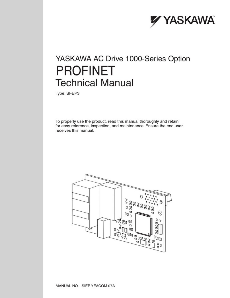
4 YASKAWA ELECTRIC SIEP YEACOM 05A 1000-Series Option SI-EM3 Modbus TCP/IP Technical Manual
1 Preface and Safety
1 Preface and Safety
Yaskawa manufactures products used as components in a wide variety of industrial systems and equipment. The selection
and application of Yaskawa products remain the responsibility of the equipment manufacturer or end user. Yaskawa
accepts no responsibility for the way its products are incorporated into the final system design. Under no circumstances
should any Yaskawa product be incorporated into any product or design as the exclusive or sole safety control. Without
exception, all controls should be designed to detect faults dynamically and fail safely under all circumstances. All systems
or equipment designed to incorporate a product manufactured by Yaskawa must be supplied to the end user with
appropriate warnings and instructions as to the safe use and operation of that part. Any warnings provided by Yaskawa
must be promptly provided to the end user. Yaskawa offers an express warranty only as to the quality of its products in
conforming to standards and specifications published in the Yaskawa manual. NO OTHER WARRANTY, EXPRESS OR
IMPLIED, IS OFFERED. Yaskawa assumes no liability for any personal injury, property damage, losses, or claims
arising from misapplication of its products.
Applicable Documentation
The following manuals are available for the SI-EM3 option:
Terms
Registered Trademarks
• Modbus TCP/IP is a trademark of Modbus-IDA.
• All trademarks are the property of their respective owners.
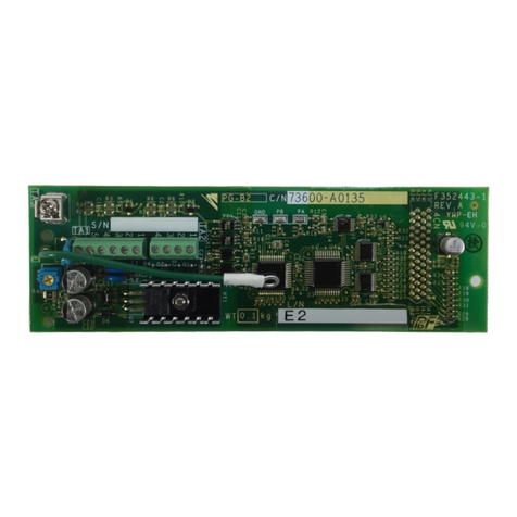
SI-EM3 Option
Yaskawa AC Drive 1000-Series Option
SI-EM3 Modbus TCP/IP Installation Manual
Manual No: TOEP YEACOM 05
Read this manual first.
The installation manual is packaged with the SI-EM3 option and
contains information required to install the option and set up related
drive parameters.
Yaskawa AC Drive 1000-Series Option
SI-EM3 Modbus TCP/IP Technical Manual
Manual No: SIEP YEACOM 05
The technical manual contains detailed information about the option.
In the U.S., access http://www.yaskawa.com to obtain the technical
manual. Customers in other areas should contact a Yaskawa
representative.
Yaskawa Drive
Yaskawa AC Drive
1000-Series Quick Start Guide The drive manuals cover basic installation, wiring, operation procedures, functions,
troubleshooting, and maintenance information.
The manuals also include important information about parameter settings and drive
tuning.
Access these sites to obtain Yaskawa instruction manuals:
U.S.: http://www.yaskawa.com
Europe: http://www.yaskawa.eu.com
Japan: http://www.e-mechatronics.com
Other areas: contact a Yaskawa representative.
Yaskawa AC Drive
1000-Series Technical Manual
Note: Indicates supplemental information that is not related to safety messages.
Drive: Yaskawa AC Drive 1000-Series
Option: Yaskawa AC Drive 1000-Series SI-EM3 Modbus TCP/IP option
