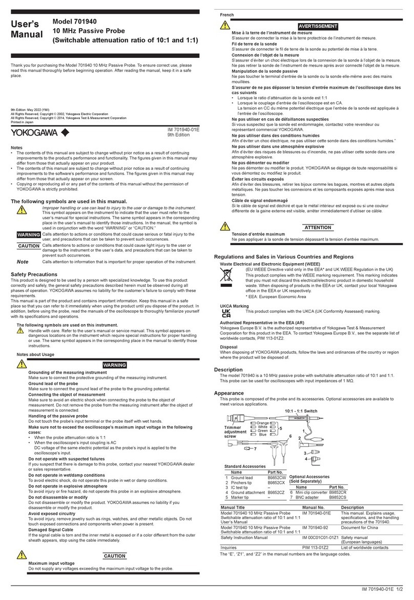
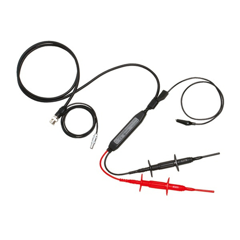
YOKOGAWA 701941 User manual

User’s
Manual
Model 701941/701942
Miniature Passive Probe
IM 701941-01E
8th Edition

1
IM701941-01E
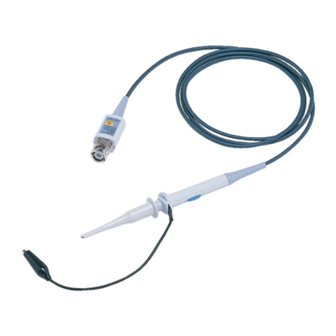
Thank you for purchasing the 701941/701942 miniature passive probe.
This 701941/701942 miniature passive probe is designed for user’s safety and
excellent easy-to-use operability. The probe tip utilizes a spring mechanism to
minimize the stress applied to a device to be inspected. Additionally, this spring
mechanism is also effective to prevent the probe tip from slipping on the board
surface. In particular, the spring mechanism is useful when using the probe
with it inclined. The probe tip is changeable. Replacement tips are provided
in the accessory pack. For details about how to change the probe tip, see
“Maintenance.” A wide variety of optional accessories is available upon request.
To ensure correct use, please read this manual thoroughly before beginning
operation. After reading this manual, keep it in a convenient location for quick
reference in the event a question arises during operation.
List of Manuals
The following manuals are provided for the 701941/701942 miniature passive
probe.
Manual Title Manual No. Notes
Model 701941/701942
Miniature Passive Probe
User’s Manual
IM 701941-01E This manual.
701941/701942 Miniature Passive Probe IM 701941-92 Document for China.
The “E” in the manual numbers are the language codes.
Contact information of Yokogawa ofces worldwide is provided on the following
sheet.
Document No. Description
PIM113-01Z2 List of worldwide contacts
Notes
• The contents of this manual are subject to change without prior notice as
a result of continuing improvements to the instrument’s performance and
functions. The gures given in this manual may differ from those that actually
appear on your screen.
• Every effort has been made in the preparation of this manual to ensure the
accuracy of its contents. However, should you have any questions or nd
any errors, please contact your nearest YOKOGAWA dealer.
• Copying or reproducing all or any part of the contents of this manual without
the permission of YOKOGAWA is strictly prohibited.
Trademarks
• Adobe and Acrobat are either registered trademarks or trademarks of Adobe
Systems Incorporated.
• In this manual, the ® and TM symbols do not accompany their respective
registered trademark or trademark names.
• Other company and product names are trademarks or registered trademarks
of their respective holders.
8th Edition: October 2017 (YMI)
All Rights Reserved, Copyright © 2004 Yokogawa Electric Corporation
All Rights Reserved, Copyright © 2011 Yokogawa Test & Measurement Corporation
2IM701941-01E
Checking the Contents of the Package
If some of the contents are not correct, or if any items are missing or damaged,
contact the dealer from which you purchased them.
701941/701942 miniature passive probe main unit
Accessories
• User's Manual (this manual): 1
• Accessory pack: 11 items (See also the list of accessories in “Replaceable
Parts.”)
• Insulation cap • IC cap
• BNC adapter • Rigid tip
• Spring tip (Ø: 0.80 mm) • Spring tip (Ø: 0.38 mm)
• Ground spring • Adjustment tool
• Pincher tip • Standard ground lead
• Color coding rings
Conventions Used in This Manual
Improper handling or use can lead to injury to the user or damage
to the instrument. This symbol appears on the instrument to
indicate that the user must refer to the user’s manual for special
instructions. The same symbol appears in the corresponding place
in the user’s manual to identify those instructions. In the manual,
the symbol is used in conjunction with the word “WARNING” or
“CAUTION.”
WARNING Describes precautions that should be observed to prevent serious
injury or death to the user.
CAUTION Describes precautions that should be observed to prevent minor
or moderate injury, or damage to the instrument.
Note Provides important information for the proper operation of the
instrument.

3
IM701941-01E
Safety Precautions
To safely operate this product and to fully utilize its functionality, strictly observe
the following cautions.
This product complies with the requirements stated in measurement categories I
and II, and pollution degree 2 dened in IEC61010-031.
If this probe is operated in a manner not specied in this manual, this may cause
the protection capability of this product to lessen.
Additionally, YOKOGAWA shall not be held responsible for defects arising
from negligence of such warning and caution, and also shall not guarantee the
product in such case.
Before using this probe, thoroughly read the instruction manual for measuring
instrument to fully understand the specications and handling precautions for
safe and correct operation.
WARNING
• Groundingofthemeasuringinstrument
The protective grounding terminal of the measuring instrument
must be connected to ground.
• Groundleadoftheprobe
Make sure to connect the ground lead of the probe to the ground
(ground potential).
• Connectingtheobjectofmeasurement
Make sure to avoid an electric shock when connecting the probe
to the object of measurement. Do not remove the probe from
the measuring instrument after the object of measurement is
connected.
• Donotoperatewithsuspectedfailures
If you suspect that there is damage to this probe, have it inspect
by a service personnel.
• Maximuminputvoltage
Do not apply any voltages exceeding the maximum input voltage
to the probe.
• Donotoperateinwet/dampconditions
To avoid electric shock, do not operate this probe in wet or damp
conditions.
• Donotoperateinexplosiveatmosphere
To avoid injury or re hazard, do not operate this probe in an
explosive atmosphere.
• Avoidexposedcircuitry
To avoid injury, remove jewelry such as rings, watches, and
other metallic objects. Do not touch exposed connections and
components when power is present.
• Observemaximumworkingvoltage
When the oscilloscope’s input coupling is AC, DC voltage of
the same electric potential as the probe’s input is applied to the
oscilloscope’s input. Make sure not to exceed the oscilloscope’s
maximum input voltage.

4IM701941-01E
Sales in Each Country or Region
Waste Electrical and Electronic Equipment
Waste Electrical and Electronic Equipment (WEEE), Directive
(This directive is valid only in the EU.)
This product complies with the WEEE directive marking requirement.
This marking indicates that you must not discard this electrical/
electronic product in domestic household waste.
Product Category
With reference to the equipment types in the WEEE directive, this
product is classied as a “Monitoring and control instruments” product.
When disposing products in the EU, contact your local Yokogawa
Europe B.V. ofce.
Authorized Representative in the EEA
Yokogawa Europe B.V. is the authorized representative of Yokogawa Test &
Measurement Corporation for this product in the EEA. To contact Yokogawa
Europe B.V., see the separate list of worldwide contacts, PIM 113-01Z2.

5
IM701941-01E
Specications
The specications described in this section apply to the miniature passive probe
connected to Yokogawa’s oscilloscope model DL1740 and may vary depending
on the type of oscilloscope connected. The preconditions for the following
specications are that the instrument should be warmed up for at least 20
minutes and the environmental conditions should not exceed the specied limits
of the probe.
ElectricalSpecications
Item 701941 701942
Attenuation Ratio110 : 1 ±2% 10 : 1 ±2%
Voltage Coefficient 0.0025%/V (typical value) 0.0025%/V (typical value)
System Bandwidth 500 MHz (-3 dB) 350 MHz (-3 dB)
Probe Rise Time < 700 ps (10% to 90%) < 1 ns (10% to 90%)
Maximum Input Voltage2400 Vrms 400 Vrms
1 This specication value is obtained when the probe is connected to an oscilloscope having an input
resistance of 1 MΩ ± 1% and the input voltage is 100 V or less.
2 See the compatible standards shown below. See also “Voltage Derating.”
Electrical Characteristics
Input Resistance (system) 10 MΩ ±2%
Input Capacitance (system) 701941: 10 pF (typical value), 701942: 18 pF (typical value)
Input Impedance (system) See also Section 6, Input Impedance.
Compensation Range 10 pF to 25 pF (typical value)
Mechanical Characteristics
Weight (probe only) Approx. 43 g
Cable Length 701941: Approx. 1.2 m, 701942: Approx. 3 m
EnvironmentalSpecications
Altitude Operating: Up to 2000 m
Storage: Up to 15000 m
Temperature Range Operating: 0 °C to 50 °C
Storage: -40 °C to 71 °C
Maximum Relative Humidity Operating: Relative humidity of 80% at a temperature
of up to 31 °C, decreasing linearly to relative
humidity of 40% at 50 °C if the temperature is
31 °C or higher.
Standards Compliance
This product is compliance with the following categories of IEC61010-031:
Measurement Category I 400 Vrms, 1250 V transient over-voltage
Measurement Category II 300 Vrms
Pollution Degree 2 Normally, only non-conductive pollution occurs.
Occasionally, however, a temporary conductivity
caused by condensation must be expected.

6IM701941-01E
DenitionsandExamplesofIECMeasurementCategory
Measurement category II
(CAT II)
Denition: Measurement category II is for
measurements performed on circuits
directly connected to the low voltage
installation.
Examples: Measurement on household appliances,
portable tools, and similar devices.
Measurement category I Denition: Measurement category I is for
measurements performed on circuits not
directly connected to a main supply.
Examples: Measurements in circuits not derived
from a main supply and specially
protected (internal) circuits derived from
a main supply.
Voltage Derating
CAUTION
As the frequency of the input signal increases, the maximum rating
of the input voltage of the probe decreases. For details about
appropriate input voltage, see “Specications.”
Typical Voltage Derating
Measurement Category I
Frequency [MHz]
Amplitude ACrms[V] Sine Waveform

7
IM701941-01E
Input Impedance
CAUTION
As the frequency of the input signal increases, the input impedance
of the probe decreases.
Typical Input Impedance
|Z| [kΩ]
Frequency [MHz]

8IM701941-01E
Handling
CAUTION
Since the spring type contact tip is very thin and sharp, great care
should be taken to prevent personal injury when the contact tip is
mounted. In particular, handle the spring type contact tip with great
care. The probe cable is a delicate part of the probe. If the probe
cable is bent or pulled forcibly, this may cause the cable to break.
To keep the accuracy and protect the product, do not apply any
impact or shock to the product.
Maintenance
Cleaning
When cleaning the exterior of the probe, clean it using a soft cloth rag moistened
with either water or isopropyl alcohol. In this case, dry the probe completely
before starting the measurement.
Changing the Probe Tip
To change the probe tip, grip the tip rmly with pliers and carefully pull it straight
out of its contact socket along the axis of the probe.
AdjustmentProcedures
LF Compensation
Connect the probe to the CAL-output on the oscilloscope and adjust the “kHz”
trimmer (see also the Figs. next page.) so that the observation waveform
becomes the optimum square waveform.
Under Compensated
Correct Waveform
Overcompensated

9
IM701941-01E
HF Compensation
Before shipment from the factory, this probe has been correctly adjusted to
Yokogawa’s digital oscilloscope DL1740 with the signal generator having 300 ps-
rise time so that the optimum square waveform is obtained. If the HF adjustment
needs to be performed, two trimmers (T1 and T2, see also the following Figs.)
are used. The T1 trimmer is used to adjust the rise time while the T2 trimmer is
used to adjust the response time of the probe.
Optimally Compensated Waveform (sample characteristics)
kHz trimmer T1 trimmer
T2 trimmer180°

10 IM701941-01E
Replaceable Parts
Replaceable parts are prepared as sets shown in the Table below. When
ordering any replaceable part set, inform a desired set name and its part
number.
Basic Set
(Part No.: B9852HA)
Accessories Basic
(Part No.: B9852HF)
Accessories Set SMD
(Part No.: B9852HG)
AccessoriesDelux
(Part No.: B9852HH)
Accessories Micro clip
(Part No.: B9852HJ)
Accessories 1
(Part No.: B9852HP)
Accessories 2
(Part No.: B9852HQ)
Accessories 3
(Part No.: B9852HR)
Accessories 4
(Part No.: B9852HS)
Probe 1
Pincher tip 2 2 2
Standard ground lead (L: 11 cm) 1 2 2 2
Adjustment tool 1 1 1
Rigid tip (Ø: 0.80 mm) 1222
Spring tip (Ø: 0.80 mm) 1222
Spring tip (Ø: 0.38 mm) 1222
Color coding rings 1 2 1 2
Insulating cap 1 2 1 2
IC cap 1 2 1 2
PCB adapter 2 3 2
Ground spring 1 2 1 3 2
Single adapter lead 1 1 1
Dual adapter lead 1 1 1
Pico hook 2 1 2
Micro clip long 2 2 2
Micro clip short 2
Adapter 2 mm plug 1
Adapter 4 mm plug 1
Ground lead with mini clip
(L: 11 cm) 111
Ground lead with 0.8 mm socket
(L: 11 cm) 111
Ground lead with 2 mm plug
(L: 22 cm) 1
Ground lead with 4 mm plug
(L: 22 cm) 1
HF-compensated ground lead
(L: 22 cm)
1 1
BNC adapter 1 1 2
Connector lead (L: 5 cm) 2 1
Connector lead (L: 10 cm) 2 1
User's manual (this manual) 1
The rating of the BNC adapter is 100 Vrms CAT II and the pollution degree is 1.
The safety of the accessories supplied with the probe has been tested.

11
IM701941-01E
List of Accessories
CAUTION
• Use ground lead only for grounding connections.
• Do not use any accessories other than those “originally” provided.
Probe
Standard ground lead (L: 11 cm)
Ground spring
Micro clip longMicro clip short
Ground lead with mini clip (L: 11 cm)
Ground lead with 0.8 mm socket (L: 11 cm)
Adapter 2 mm plug (L: 22 cm)
Adapter 4 mm plug (L: 22 cm)
HF-compensated ground lead (L: 22 cm)
76.1(3.00)
Ø 17.8(0.70)
Ø 3.5(0.14)
100(3.94)
Ø 15(0.59)
Ø 6.5(0.26)
29.9(1.18)
41.4(1.63)
2(0.08)
5.6(0.22)
18(0.71)
Ø 0.6 (0.02)
Ø 0.6 (0.02)
Ø 0.8 (0.03)
Ø 0.8 (0.03)
43(1.69)31(1.22)
Unit: mm
(approx. inch)

12 IM701941-01E
Pincher tip
Adjustment tool
Rigid tip
(Ø: 0.80 mm)
Ground lead with 2 mm plug
Ground lead with 4 mm plug
Spring tip
(Ø: 0.80 mm)
Insulating cap
IC cap
Spring tip
(Ø: 0.38 mm)
Color coding rings (9 colors* × 2)
PCB adapter
Single adapter lead
Dual adapter lead
Connector lead (L: 10 cm)
Connector lead (L: 5 cm)
*Colors: Brown, red, orange,
yellow, green, blue,
purple, gray, white
6.6(0.26) 7(0.28)
60(2.36)24(0.95)
24(0.95)
55.6(2.19)
16.5(0.65) 13.5(0.53)
25.4(1.00) 25(0.99)
61.5(2.42)
1.6(0.06)
22.5(0.89)
38.7(1.52)
57.3(2.26)
78(3.07)
60(2.36)
50(1.97)
100(3.94)
Ø2.4(0.09)
Ø2.4(0.09)
Ø8.4(0.33)
0.7(0.03)
2(0.08)
Pico hook
BNC adapter

Printed in Germany
This manual suits for next models
1
Table of contents
Other YOKOGAWA Analytical Instrument manuals

YOKOGAWA
YOKOGAWA Vigilantplant NFBU200-S Series User manual

YOKOGAWA
YOKOGAWA EXAxtZR User manual

YOKOGAWA
YOKOGAWA ZR202G User manual

YOKOGAWA
YOKOGAWA 701940 User manual

YOKOGAWA
YOKOGAWA MG8G User manual

YOKOGAWA
YOKOGAWA ZR22S User manual

YOKOGAWA
YOKOGAWA 701940 User manual

YOKOGAWA
YOKOGAWA OX100 User manual

YOKOGAWA
YOKOGAWA EXAxt ZR22G Manual

YOKOGAWA
YOKOGAWA ZR Series Specification sheet