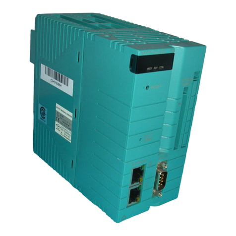
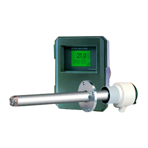
YOKOGAWA ZS8 User manual

User’s
Manual Model ZS8
Flameproof
Zirconia Oxygen Analyzer
IM 11M7A3-01E
IM 11M7A3-01E
6th Edition
TM

<PREFACE> i
IM 11M7A3-01E
tPREFACE
This instruction manual describes the handling of the ameproof zirconia oxygen analyzer.
To ensure safe operation and maximum performance of ameproof zirconia oxygen analyzer,
read this manual carefully before using it.
Items to which attention needs to be paid with regard to the handling of the ameproof zirconia
oxygen analyzer, are shown in this manual in the form of
WARNING and CAUTION.
These items must be read before it is put in operation.
WARNING
Items involving serious accidents due to incorrect handling of ameproof zirconia oxygen
analyzer.
CAUTION
Items involving injury, damage to device or physical damage.
WARNING
• Power source
Before the power for the unit is turned ON, make sure that the power voltage conforms to
the power supply voltage.
• Earthing
Before turning ON the power for the unit, be sure to earth the unit to prevent electric shocks.
• Necessity of earthing
Neither cut o the internal (or external) earth cable of the unit, nor disconnect the earth
terminal, otherwise, it causes a hazard to human body.
• Defect in function
If protective functions such as earthing, fuse, etc. seem to be defective, do not operate the
unit. Before operating the unit, check to make sure that the protective functions are not
defective.
• Fuse
To prevent re accidents, be sure to use the specied type of fuse. Do not attempt to use
other types of fuses. Care should be taken not to short the fuse holder.
When it becomes necessary to replace fuse, turn OFF the power switch and disconnect the
unit from the main power source.
• Do not touch the inside.
The unit has high-voltage circuits. Do not touch the inside of the unit when the power is
ON. Do not replace or repair the unit by yourself. Contact our service-man or authorized
engineer.
• External connection
The unit must be earthed before connecting it to measuring object or external control circuit.
• Prohibition of modication or mounting of additional parts in unit
Do not attempt to modify or mount additional parts in the unit, otherwise, it aects the safe
operation or damages the unit.
Media No. IM 11M7A3-01E 6th Edition: Nov. 2019
All Rights Reserved Copyright © 1996, Yokogawa Electric Corporation

<PREFACE>
ii
IM 11M7A3-01E
WARNING
• Before opening the cover of the ZS8C converter, remove power and make sure of non-
hazardous (*) atmospheres.
• When the ambient temperature of the converter exceeds 50ºC, use wire resistant to 70ºC or
greater for external wiring.
(*) The text plate says "Open circuit at non-hazardous location before removing cover," since the internal energy of the ZS8C
converter decreases under the specied value.
The denition of the non-hazardous area is followed by the description in the Users Guide to Installing Flameproof
Electrical Apparatus at Plants, issued by the Technology Institution of Industrial Safety, Japan: As a non-hazardous area
is considered a place where no occurrence of explosive gas atmospheres is guaranteed by the foreperson and conrmed
by a written document. Therefore, if non-hazardous area is secured, it is allowed to open the cover in the eld.
• Before opening the cover of the ZS8D detector, remove power and allow the detector to
stand at least 40 minutes.
• When the ambient temperature of the detector exceeds 30ºC, use wire resistant to 70ºC or
greater for external wiring.
• The detector cannot be used except in mixed gases composing air or mixed gas with
oxygen concentration lower than air, or combustible gas or vapor.
CAUTION
• Choose a suitable location for installation.
The unit should be installed in a place of normal temperature and humidity where there
is less change in temperature and the unit is not exposes to strong radian heat and direct
sunlight.
Since the unit is designed for indoor use, choose a place free from direct wind/rain or use a
suitable case cover.
• Do not use the unit in a place with vibration.
• Cleaning of instrument
Do not use benzine or thinner for cleaning, as it deforms or cracks the unit.
• Use in good atmosphere
The unit should be used in a clean place free from corrosive or combustible gas.
• Caution to electric shocks
The earth cable must be earthed to prevent electric shocks.
• Key operation
Do not operate the keys on the front of the instrument with a sharp-end object.

<PREFACE> iii
IM 11M7A3-01E
Introduction
The EXA OXY Model ZS8 Flameproof Oxygen Analyzer is used for combustion status monitoring
or control in processes which require combustion control in every eld. There are several types
of EXA OXY detectors, and the auxiliary equipment needed for optimum measurement are also
available. Also, devices for automating calibration are available. As stated above, since many
kinds of equipment and devices are available for this EXA OXY analyzer, select the appropriate
devices and construct the optimum measuring system when this model is to be used.
This manual describes the installation, operation, inspection and maintenance of almost all of the
equipment related to EXA OXY systems. Read the instructions thoroughly before you handle the
equipment but you may skip sections on equipment which is not included in your system.
The types of equipment described in this manual and the contents for each one are as shown
below.
Types of Equipment Described in This Manual and Contents for Each One
Model Product Name
Items Described in the Manual
Speci
cations
Instal
lation Operation Mainte
nance CMPL
ZS8D-L General-purpose detector
ZS8D-H High-temperature detector
ZS8C Converter
ZS8P-H Probe adaptor
ZA8F Flow setting unit
—Ejector assembly
(Part No.: K9292VA/VB/WA/WB)
—Calibration gas unit case (Part
No.: E7044KF)
CAUTION
There are two types of general-purpose detectors: one which vents to the outside of a furnace
the mixed gases of a sample gas suctioned in by the ejector and ejector air, and another which
returns mixed gases to the furnace. High-temperature detectors all vent to the outside of a
furnace. Vent the mixed gas of a sample gas and ejector air to a place where no safety problems
will occur (the venting owrate should be 40 to 50 l/min). A general-purpose detectors may
be a “return to the furnace” type. A return pipe is provided as standard. However, be cautious
in returning gas to a furnace because air is blown into the furnace. The normal ow rate of
Netwrining gas is approximately 3 l/min to 5 l/min.

<PREFACE>
iv
IM 11M7A3-01E
This manual takes the following conguration. A brief description of each chapter and the
chapters to be referred to for installation, operation and maintenance are given.
Chapter conguration of the manual and items to be referred to.
Chapter Conguration of This Manual and Items to be Referred to
Chapter Brief description
For reference to
Instal
lation Operation Mainte
nance
1. General System component units for the EXA OXY
zirconia oxygen analyzer and system
conguration are shown.
2. Installation Installation procedures for each unit are
described.
3. Piping Piping procedures are explained for four
standard system congurations.
4. Wiring Wiring procedures are given for each system,
such as power supply wiring, output signal
wiring, etc.
5. Components
and their
functions
Names and major functions of components of
main units in the manual are illustrated.
6. Operation Basic procedures are presented to put the EXA
OXY analyzer into the operation status.
7. Operating
keys and
display of
converter
Converter key operations and items related to
the display are detailed.
8. Calibration Calibration procedures carried out as
necessary are described.
9. Inspection
and
maintenance
Inspection items to maintain the EXA OXY
analyzer performance and procedures for
replacing deteriorated parts and components
are described.
10. Trouble
shooting
Countermeasures when the system fails and/or
disposition for failure are shown.
Customer
maintenance
parts list
Parts that can be freely replaced by the user if
damaged are illustrated for each unit.
: Thoroughly read the instructions and do work after fully understanding the contents.
: Before actual work, rst read the description or refer to it if necessary.
: It is recommended that you read the description.
nTrademark Notices
• EXA OXY is a trademark of Yokogawa Electric Corporation.
• All other company and product names mentioned in this user’s manual are trademarks or
registered trademarks of their respective companies.
• We do not use TM or ® mark to indicate those trademarks or registered trademarks in this
user’s manual

<PREFACE> v
IM 11M7A3-01E
Precautions for Flameproof Instruments
1. General
Instruments with Flameproof construction (hereafter referred to as ameproof instruments) are
tested and certied by the public authority in accordance with the Labor Safety and Health Laws
of Japan.
A certied instrument is provided with a certication label and a nameplate that states
specications required for explosion protection performance. All installations of certied
instruments should be executed in compliance with the nameplate specications.
For details, see USERS' GUIDELINES for Electrical Installation for Explosive Gas Atmospheres
in General Industry, issued by the Research Institute of Industrial Safety of the Ministry of Labor
in Japan, 1994.
2. Flameproof Instruments
Instruments that can be termed "ameproof" must satisfy the following conditions.
They must have been tested and certied by an ocial body in accordance with the Industrial
Safety and Health Act and must carry a certication label on them.
They must be used in accordance with the specications stated on the nameplate.
The following operating conditions must be observed.
(1) ZS8D Detector
(a) Before opening the cover, remove power and allow the detector to stand at least 40
minutes.
(b) When the ambient temperature of the detector exceeds 30ºC, use wire resistant to
70ºC or greater for external wiring.
(c) The detector cannot be used except in mixed gases composing air or mixed gas with
oxygen concentration lower than air, or combustible gas or vapor.
(2) Converter
(a) Before opening the cover, remove power and make sure of non-hazardous
atmospheres. The warning added on page i must be observed.
(b) When the ambient temperature of the converter exceeds 50ºC, use wire resistant to
70ºC or greater for external wiring.
3. Flameproof Instrument Installation
(1) Installation Area
Flameproof instruments may be installed in hazardous areas where the specied gases are
present. They should not be installed in Division 0 areas.
Note: Hazardous areas are distinguished based on the frequency and duration of the occasions when explosive atmospheres are
encountered (IEC standard 79-10 classication of hazardous areas).
Areas where explosive atmospheres are continuously present or persist for long periods are classied as Division 0.
Areas where there is a risk that an explosive atmosphere will be encountered during normal operation of the equipment and
facilities are classied as Division 1.
Areas where there is no risk that an explosive atmosphere will be encountered during normal operation of the equipment and
facilities, and where an explosive atmosphere will persist for only a short period even if encountered, are classied as Division 2.
(2) Environmental Conditions
The standard environmental condition for ameproof instrument installation is an ambient
temperature range of −20 to 40°C. If the equipment is installed where there is a risk that it may be
exposed to radiant heat from plant equipment, direct sunlight, etc., take steps to heat-insulate the
equipment.
<PREFACE>
vi
IM 11M7A3-01E
4. External Wiring for Flameproof Instruments
External wiring for ameproof instruments must employ cable wiring. Securely ground all non-
live metal parts. For details, see USERS’ GUIDELINES for Electrical Installation for Explosive
Gas Atmospheres in General Industry, issued by the Research Institute of Industrial Safety of the
Ministry of Labor in Japan, 1994.
It is recommended to use cable glands for wiring.
• Use PVC insulated and sheathed control cable CVV (JIS C 3401) or equivalent. Where
protection from external physical damage is required, the cable must be enclosed in steel
conduit.
• Connections between such cables, or between such cables and wiring routed through
ameproof metal conduit, must be enclosed in a ameproof junction box per item (2), to
prevent any explosive gases from entering and ame fronts from moving in cables.
• For instruments in which cables are to be brought in through ameproof packings, use the
ameproof packing glands specied for use with the instruments and select the ameproof
packings whose internal diameters are appropriate for the cable external diameters.
• If a ameproof packing gland is used, screw it into the connection port so that a minimum
of ve threads are fully engaged, and fasten securely with a lock nut. It is mandatory that a
nonhardening sealant be applied to the threads for waterproong.
• The ameproof gland packing should be securely tightened to prevent the passage of
explosive gases or ame fronts.
5. Maintenance of Flameproof Instruments
When opening the cover for maintenance, the warning added on page i must be observed.
(1) Maintenance with Power ON
Maintenance of ameproof instruments with power on should be avoided unless there is no
alternative. However, if maintenance with power on cannot be avoided, a gas detector should
rst be used to verify that an explosive atmosphere is not present, before the instrument
cover is opened. If it is not possible to verify that explosive gases are not present, the scope of
maintenance should be limited to the following:
(a) Visual inspection
Visually inspect the ameproof instrument, metal conduit, cables, etc., for physical
damage and corrosion, and other mechanical and structural defects.
(b) Key operation
Adjustment should be made only to the extent that it can be done from the outside
without opening the instrument cover. Great care must be taken not to cause
mechanical sparks with tools.

<PREFACE> vii
IM 11M7A3-01E
(2) Repairs
If a ameproof instrument requires repair, turn o the power, and carry the instrument to a
nonhazardous area. Observe the following points during repair:
(a) Make only such electrical and mechanical repairs as will restore the equipment to its
original condition. In the case of a Flameproof instrument, mechanical aspects such
as the gaps and path lengths of joints and mating surfaces, and mechanical strength
of enclosures, are critical factors in explosion protection. Exercise great care not to
damage the joints and mating surfaces, and to protect enclosures from shock.
(b) If damage is incurred by any area of a part critical to the maintenance of ameproof
performance (for example, threads, joints or mating surfaces, inspection windows,
connecting section between transmitter and terminal box, shrouds or clamps, external
wiring connection ports, etc.), contact Yokogawa.
Note: Never rethread a threaded connection or renish or touch up the nish on a joint or mating surface.
Doing so is extremely dangerous, as the ameproof explosion protection will be compromised.
(c) Unless otherwise specied, electrical circuits and mechanisms inside the enclosure
may be repaired by component replacement, as this will not directly aect ameproof
explosion protection (however, the instrument should always be restored to its original
condition). Only Yokogawa-specied parts should be used for repair.
(d) Before returning a repaired instrument to service, always reinspect all parts necessary
for the preservation of ameproof explosion protection. Verify that all screws, bolts,
nuts, and threaded connections are properly tightened.
(3) Prohibition of Specication Changes and Modications
Users are prohibited from making any modications to specications or physical conguration,
such as adding or changing the conguration of external wiring ports.
6. Flameproof Packing Gland Selection
CAUTION
The ameproof packing glands used at the external wiring connection ports of Flameproof
instruments conforming to IEC standards are certied in combination with the ameproof
instruments. Therefore, only those ameproof packing glands specied by Yokogawa should be
used.

<PREFACE>
viii
IM 11M7A3-01E
After-Sales Warranty
nDo not modify the product.
nYokogawa warrants the product for the period stated in the pre-purchase
quotation. Yokogawa shall conduct dened warranty service based on its
standard. When the customer site is located outside of the service area, a fee
for dispatching the maintenance engineer will be charged to the customer.
nDuring the warranty period, for repair under warranty carry or send the
product to the local sales representative or service oce. Yokogawa will
replace or repair any damaged parts and return the product to you.
• Before returning a product for repair under warranty, provide us with the model name
and serial number and a description of the problem. Any diagrams or data explaining the
problem would also be appreciated.
• If we replace the product with a new one, we won't provide you with a repair report.
nIn the following cases, customer will be charged repair fee regardless of
warranty period.
• Failure of components which are out of scope of warranty stated in instruction manual.
• Failure caused by usage of software, hardware or auxiliary equipment, which Yokogawa did
not supply.
• Failure due to improper or insucient maintenance by user.
• Failure due to misoperation, misuse or modication which Yokogawa does not authorize.
• Failure due to power supply (voltage, frequency) being outside specications or abnormal.
• Failure caused by any usage out of scope of recommended usage.
• Any damage from re, earthquake, a storm and ood, lightning, disturbance, riot, warfare,
radiation, and other natural changes.
n Yokogawa does not warrant conformance with the specic application at the
user site. Yokogawa will not bear direct/indirect responsibility for damage due
to a specic application.
n Yokogawa will not bear responsibility when the user congures the product
into systems or resells the product.
n Maintenance service and supplying repair parts will be covered for ve years
after the production ends. For repair this product, please contact the nearest
sales oce described in this instruction manual.

i
IM 11M7A3-01E
<CONTENTS>
Model ZS8
Flameproof
Zirconia Oxygen Analyzer
CONTENTS
IM 11M7A3-01E 6th Edition
tPREFACE........................................................................................................i
Introduction..................................................................................................iii
Precautions for Flameproof Instruments ............................................................ v
After-Sales Warranty.................................................................................viii
1. General ...................................................................................................... 1-1
1.1 System Conguration ...................................................................................... 1-1
1.2 Specications.................................................................................................... 1-6
1.2.1 General Specications ....................................................................... 1-6
1.2.2 Characteristics ................................................................................... 1-7
1.2.3 Flameproof Detector ZS8D ................................................................ 1-7
1.2.4 High Temperature Probe Adaptor ZS8P-H ...................................... 1-14
1.2.5 Flameproof Converter ZS8C ........................................................... 1-16
1.2.6 Options ............................................................................................. 1-20
2. Installation................................................................................................. 2-1
2.1 Installation of Flameproof General-purpose Detector.................................. 2-1
2.1.1 Installation Site ................................................................................... 2-1
2.1.2 Probe Insertion Hole .......................................................................... 2-1
2.1.3 Detector Installation ........................................................................... 2-2
2.1.4 Reference Air Outlet ........................................................................... 2-2
2.1.5 Heat Insulation ...................................................................................2-3
2.2 Installation of Flameproof High-temperature Detector ................................ 2-3
2.2.1 Installation Site ................................................................................... 2-3
2.2.2 Probe Insertion Hole .......................................................................... 2-3
2.2.3 Detector Installation ........................................................................... 2-4
2.2.4 Ejector Installation .............................................................................. 2-5
2.2.5 Heat Insulation ...................................................................................2-6
2.2.6 Blocking Radiant Heat ....................................................................... 2-6
2.3 Heat Insulation .................................................................................................. 2-6
2.3.1 Surface Temperature of Detector....................................................... 2-6
2.3.2
Portions Requiring Heat Insulation and Temperature to be Maintained
2-6
2.3.3 Methods to Change the Surface Temperature .................................. 2-7
2.3.4 Fitting a Thermal Insulating Jacket (Option) ...................................... 2-8
2.3.5 Heating and Insulation Range when Not Using a Heat-Insulating Jacket
2-15

ii
IM 11M7A3-01E
<CONTENTS>
2.4 Installation of Converter................................................................................. 2-18
2.4.1 Installation Site ................................................................................. 2-18
2.4.2 Converter Mounting ......................................................................... 2-18
2.5 Installation of Flow Setting Unit .................................................................... 2-19
2.5.1 Installation Site ................................................................................. 2-19
2.5.2 Flow Setting Unit Mounting .............................................................2-20
2.6 Installation of Calibration Gas Unit Case ..................................................... 2-21
2.6.1 Installation Site ................................................................................. 2-21
2.6.2 Mounting .......................................................................................... 2-21
3. Piping......................................................................................................... 3-1
3.1 System ............................................................................................................... 3-1
3.2 Parts Required for Piping................................................................................. 3-2
3.3 Calibration Gas Piping ..................................................................................... 3-2
3.4 Reference Gas Piping....................................................................................... 3-3
3.5 Piping to Probe Adaptor................................................................................... 3-3
3.6 Purge Gas Piping .............................................................................................. 3-4
3.6.1 Piping for Air Purge in Converter ....................................................... 3-4
3.6.2 Air Supply for Air Purging ................................................................... 3-4
4. Wiring......................................................................................................... 4-1
4.1 Safety Precaution for External Wiring ............................................................ 4-1
4.1.1 Wiring Precautions ............................................................................. 4-1
4.1.2 Care During Wiring ............................................................................ 4-2
4.1.3 Cables ................................................................................................ 4-4
4.1.4 Mounting of Cable Gland ................................................................... 4-5
4.2 Wiring for Detector Signal................................................................................ 4-6
4.2.1 Cable Specications .......................................................................... 4-6
4.2.2 Connection to Detector ...................................................................... 4-6
4.2.3 Connection to Converter .................................................................... 4-6
4.3 Wiring for Detector Heater Power ................................................................... 4-7
4.3.1 Wiring for Sensor Heater Power (In the case of steam heater) ......... 4-7
4.3.2 Wiring for Detector Heater Power (In the case of electric heater) ..... 4-7
4.3.3 Cable Specications .......................................................................... 4-7
4.3.4 Connection to Detector ...................................................................... 4-7
4.3.5 Connection to Converter .................................................................... 4-7
4.4 Wiring for Analog Output ................................................................................. 4-8
4.4.1 Cable Specications .......................................................................... 4-8
4.4.2 Wiring Procedure ............................................................................... 4-8
4.5 Power and Ground Wiring ............................................................................... 4-9
4.5.1 Power Wiring ...................................................................................... 4-9
4.5.2 Ground Wiring .................................................................................... 4-9
4.6 Digital Communication Wiring ...................................................................... 4-12
4.6.1 Wiring of RS-422-A Communication Cable ..................................... 4-12

iii
IM 11M7A3-01E
<CONTENTS>
4.6.2 ZS8C Converter Communication (RS-422-A) Specications ........ 4-13
4.7 Contact Output Wiring.................................................................................... 4-21
4.7.1 Cable Specications ........................................................................ 4-21
4.7.2 Wiring Procedure .............................................................................4-21
4.8 Contact Input Wiring....................................................................................... 4-22
4.8.1 Cable Specications ........................................................................ 4-22
4.8.2 Wiring Procedure .............................................................................4-22
4.9 Wiring for Solenoid Valve............................................................................... 4-22
5. Components and Their Functions.......................................................... 5-1
5.1 Detector.............................................................................................................. 5-1
5.1.1 General-purpose Detector ................................................................. 5-1
5.1.2 High-temperature Detector (with a high-temperature probe adaptor) 5-2
5.2 Converter ........................................................................................................... 5-3
5.3 Flow Setting Unit............................................................................................... 5-4
6. Operation................................................................................................... 6-1
6.1 Startup................................................................................................................ 6-1
6.1.1 Inspection of Piping and Wiring Conditions ....................................... 6-1
6.1.2 Checking the Heat Insulation Conditions ........................................... 6-1
6.1.3 Checking of Set Valves ...................................................................... 6-2
6.1.4 Supplying Power to Converter ........................................................... 6-2
6.1.5 During Warming-up ............................................................................ 6-2
6.1.6 Data Setting (To set data, enter the password “16”) .......................... 6-2
6.1.7 Set of Relay Contacts for Contact Output ........................................ 6-17
6.1.8 Supplying Pressure to Ejector ......................................................... 6-18
6.1.9 Calibration ........................................................................................ 6-19
6.1.10 Checking Functional Operations ..................................................... 6-20
6.2 Stationary Operation ...................................................................................... 6-20
6.2.1 Collection of Control Data ................................................................ 6-20
6.2.2 Troubleshooting ............................................................................... 6-20
6.2.3 Checking Operating Conditions ....................................................... 6-21
6.2.4 Stopping and Restarting Operations .............................................. 6-22
7. Operating Keys and Display of Converter............................................. 7-1
7.1 Operating Keys ................................................................................................. 7-1
7.1.1 Types and Functions of Operating Keys ............................................ 7-1
7.1.2 Examples of Applications of the Operating Keys ............................... 7-2
7.2 Readout Displays.............................................................................................. 7-6
7.2.1 Status Display .................................................................................... 7-6
7.2.2 Data Display ....................................................................................... 7-6
7.2.3 Message Display................................................................................ 7-6
8. Calibration................................................................................................. 8-1
8.1 General............................................................................................................... 8-1

iv
IM 11M7A3-01E
<CONTENTS>
8.1.1 Principles of Zirconia Oxygen Analyzer ............................................. 8-1
8.1.2 Calibration Gas .................................................................................. 8-2
8.1.3 Compensation .................................................................................... 8-2
8.1.4 Characteristic Data from a Sensor Measured During Calibration ..... 8-3
8.2 Calibration Procedures .................................................................................... 8-4
8.2.1 Operation Flowchart of Semi-Automatic and Automatic Calibrations8-4
8.2.2 Operation Flowchart .......................................................................... 8-5
8.3 Methods of Operating Valves in the ZA8F Flow Setting Unit....................... 8-7
8.3.1 Preparation before Calibration ........................................................... 8-7
8.3.2 Operating the Span Gas Flow Setting Valve ..................................... 8-7
8.3.3 Operating the Zero Gas Flow Setting Valve ...................................... 8-7
8.3.4 Treatment after Calibration ................................................................ 8-7
9. Inspection and Maintenance................................................................... 9-1
9.1 Inspection and Maintenance of the Detector................................................. 9-1
9.1.1 Precautions for Inspecting the Detector ............................................ 9-1
9.1.2 Checking the Flow of Sucked Sample Gases ................................... 9-1
9.1.3 Calibration of Indication ..................................................................... 9-2
9.1.4 Checking the Flow Setting Unit During Normal Operation ................ 9-2
9.1.5 Cleaning the Sensor Assembly .......................................................... 9-2
9.1.6 Cleaning the Calibration Gas Tube .................................................... 9-3
9.1.7 Replacing the Sensor Assembly ........................................................ 9-4
9.1.8 Cleaning the High-Temperature Probe Adapter ................................ 9-6
9.2 Inspection and Maintenance of the Converter .............................................. 9-7
9.2.1 Replacing Fuses ................................................................................ 9-7
9.2.2 Replacing the Message Display Unit ................................................. 9-8
10. Troubleshooting ..................................................................................... 10-1
10.1 Disposal When an Error Code Is Displayed................................................. 10-1
10.1.1 Types of Error Codes ...................................................................... 10-1
10.1.2 Causes of “E--1 Sensor (Cell) Failure” and Procedure for Restoration 10-2
10.1.3
Causes of “E--2 Sensor Temperature Error (Low)” and Procedure for Restoration 10-3
10.1.4
Causes of “E--3 Sensor Temperature Error (High)” and Procedure for Restoration
10-4
10.1.5
Causes of “E--4 A/D (Analog Circuit) Failure” and Procedure for Restoration 10-5
10.1.6
Causes of “E--5 Calibration Value Error (Zero)” and Procedure for Restoration 10-6
10.1.7
Causes of “E--6 Calibration Value Error (Span)” and Procedure for Restoration
10-6
10.1.8
Causes of “E--7 EMF Stabilization Time Over” and Procedure for Restoration 10-7
10.1.9
Causes of “E--8 ROM and RAM Failure” and Procedure for Restoration 10-8
10.1.10
Causes of Display Disappearance (Data Display) and Procedure for Restoration 10-8
10.2 Where the Output Response Is Too Slow .................................................... 10-9
10.2.1 Checking the Main Ejector for Clogging .......................................... 10-9
10.2.2 Checking the Auxiliary Ejector for Clogging ..................................... 10-9
10.2.3 Checking the Tip Filter (SiC) for Clogging .......................................10-9

v
IM 11M7A3-01E
<CONTENTS>
10.2.4 Others .............................................................................................. 10-9
10.3 Measures When Measured Value Shows an Error...................................... 10-9
10.3.1 Measured Value Higher Than True Value ........................................ 10-9
10.3.2 Measured Value Lower Than True Value ...................................... 10-11
10.3.3 Measured Value Sometimes Show Abnormal Values ................... 10-11
Customer Maintenance Parts List..........................................CMPL 11M7A3-01E
Customer Maintenance Parts List..........................................CMPL 11M7A3-03E
Customer Maintenance Parts List..........................................CMPL 11M7A3-04E
Customer Maintenance Parts List..........................................CMPL 11M7A3-11E
Revision Record.......................................................................................................i

Blank Page

<1. General> 1-1
IM 11M7A3-01E
1. General
The ZS8 ameproof zirconia oxygen analyzer can be used for monitoring and controlling
oxygen concentrations in combustion gases in heating furnaces or boilers in petroleum rening,
petrochemical and city gas production industries.
The analyzer mainly consists of a detector and a converter. The ZS8 ameproof detector
includes general-purpose detectors that can be used for measuring gases at up to 800°C and
high- temperature detectors that can be applied to measuring gases at 800°C or more. These
detectors are both direct-insertion detector. This allows the detectors to be mounted on ue walls
or the like to measure internal gases directly. The converter has good operability and is provided
with many functions (measurement and computing functions and maintenance functions such
as self-diagnosis) as standard. In addition, digital communication functions can be added. For
calibration, one-touch calibration can be performed with key operation of the converter by using
the ZA8F ow setting unit and making zero and span gases ow. As stated above, since the ZS8
ameproof zirconia oxygen analyzer is provided with a number of functions and many auxiliary
units, the optimum system can be constructed by selecting the units matching an application.
1.1 System Conguration
The ZS8 oxygen analyzer is composed of the following units:
(1) ZS8D ameproof detector
(2) ZS8C ameproof converter
(3) ZA8F ow setting unit
(4) Calibration gas unit (consists of a zero-gas cylinder, pressure regulator, and case
assembly).
However, note that the units to be used dier depending on the specications.

<1. General>
1-2
IM 11M7A3-01E
n Examples of System Conguration
(1) Example of Heat Insulation with Electric Heater (for the ZS8D-L ameproof detector)
Interior of
furnace
Heat insulation
Wiring for heat insulation
Provided by heaters
Detector output wiring
(1.25mm2or more, 8-wire shielded cable)
Pressure gauge 20kPa *4
Stop valve Air set
Detector heater power wiring
(2mm2or more, 4-wire shielded cable)
Ejector air
Check valve
4 to 20mA DC
output
Contact output
Contact input
100V, 115 V AC
Air set (G7003XF, K9473XK)
Calibration-gas
pressure
regulator
Calibration-gas
pressure
regulator
Calibration-gas
flow meter
600 ml/min ±10%
Reference-gas flow meter
300 ml/min ±20%
Needle valve
Needle valve
Calibration
gas *3
Reference
gas
Needle valve
Instrument
air
Flow setting unit (ZA8F) Zero-gas cylinder
Calibration-gas unit
Span-gas
cylinder
Calibration-gas unit
P
P
P P
P P
Conduit *1 ZS8C
Flameproof converter
*2
Non-hazardous
location
Hazardous
location
(K9292DN,
K9292DS)
(G7013XF,
G7014XF) (G7001ZC)
ZS8D
Flameproof detector
*2
F1.1E.ai
MEAS
MAINT
ALM
FAIL
DATA
vol%O
*1: Conduits
1) When installing conduits, use exible conduits so that the probe removed.
2) Use a shielded cable for the signal cable and ground the shield together with the probe ground.
3) Provide separate conduits for the signal and heater lines.
4) The maximum outside diameter of the cable suited for the cable gland used for the instrument is 13.5mm (in case
that the thread at the conduit side is G3/4)
*2: The probe material SUS310S or SiC should be selected according to the specied measurement gas temperature
(SUS310S: 0 to 800°C, SiC: 800 to 1400°C).
*3: For the zirconia oxygen analyzer, 100% nitrogen cannot be used as the zero gas. Generally, approximately a 1 vol%
oxygen (nitrogen gas balance) mixture is used.
*4: The setting of the ejector supply air pressure depends on the furnace pressure.

<1. General> 1-3
IM 11M7A3-01E
(2) Example of Heat Insulation with Electric Heater (for the ZS8D-H ameproof high-
temperature detector)
Interior of
furnace
Heat insulation
Wiring for heat insulation
Provided by heaters
Auxiliary ejector air
Detector output wiring
(1.25mm2or more, 8-wire shielded cable)
Pressure gauge 20kPa *4
Pressure gauge 98kPa *4
Stop valve
Stop valve
Air set
Air set
Detector heater power wiring
(2mm2or more, 4-wire shielded cable)
4 to 20mA
DC output
Contact output
Contact input
100V, 115 V AC
Check valve
Air set
Calibration-gas
pressure
regulator
Calibration-gas
pressure
regulator
Calibration-gas
flow meter
600 ml/min ±10%
Reference-gas
flow meter
300 ml/min ±20%
Needle valve
Needle valve
Calibration
gas *3
Reference
gas
Needle valve
Instrument
air
Flow setting unit (ZA8F) Zero-gas cylinder
Calibration-gas unit
Span-gas
cylinder
Calibration-gas unit
P
P
P P
P P
P
Conduit *1
High
temperature
probe
adaptor *2
ZS8C
Flameproof
converter Hazardous location
Non-hazardous
location
(G7003XF, K9473XK)
(K9292DN,
K9292DS)
(G7013XF,
G7014XF)
(G7001ZC)
F1.2E.ai
MEAS
MAINT
ALM
FAIL
DATA
vol%O
Main ejector air
*1: Conduits
1) When installing conduits, use exible conduits so that the probe removed.
2) Use a shielded cable for the signal cable and ground the shield together with the probe ground.
3) Provide separate conduits for the signal and heater lines.
4) The maximum outside diameter of the cable suited for the cable gland used for the instrument is 13.5mm (in case
that the thread at the conduit side is G3/4)
*2: The probe material SUS310S or SiC should be selected according to the specied measurement gas temperature
(SUS310S: 0 to 800°C, SiC: 800 to 1400°C).
*3: For the zirconia oxygen analyzer, 100% nitrogen cannot be used as the zero gas. Generally, approximately a 1 vol%
oxygen (nitrogen gas balance) mixture is used.
*4: The setting of the ejector supply air pressure depends on the furnace pressure.

<1. General>
1-4
IM 11M7A3-01E
(3) Example of Steam Trace Heat Insulation (for the ZS8D-L ameproof detector)
Interior of
furnace
Heat insulation
Steam outlet
Steam inlet
Pressure gauge 20kPa *4
Stop valve Air set
Detector heater power wiring
(2mm2or more, 2-wire shielded cable)
Ejector air
Check valve
4 to 20mA
DC output
Contact output
Contact input
100V, 115 V AC
Air set
Calibration-gas
pressure regulator
Calibration-gas
pressure regulator
Calibration-gas
flow meter
600 ml/min ±10%
Reference-gas
flow meter
300 ml/min ±20%
Needle valve
Needle valve
Calibration
gas *3
Reference
gas
Needle valve
Instrument
air
Flow setting unit (ZA8F) Zero-gas cylinder
Calibration-gas unit
Span-gas
cylinder
Calibration-gas unit
P
P
P P
P P
Detector output wiring
(l.25mm2or more, 6-wire shielded cable)
Conduit *1
ZS8D
Flameproof detector
*2
ZS8C
Flameproof
converter
Non-hazardous
location
Hazardous
location
(G7003XF, K9473XK)
(K9292DN,
K9292DS)
(G7013XF,
G7014XF) (G7001ZC) F1.3E.ai
MEAS
MAINT
ALM
FAIL
DATA
vol%O
*1: Conduits
1) When installing conduits, use exible conduits so that the probe removed.
2) Use a shielded cable for the signal cable and ground the shield together with the probe ground.
3) Provide separate conduits for the signal and heater lines.
4) The maximum outside diameter of the cable suited for the cable gland used for the instrument is 13.5mm (in case
that the thread at the conduit side is G3/4)
*2: The probe material SUS310S or SiC should be selected according to the specied measurement gas temperature
(SUS310S: 0 to 800°C, SiC: 800 to 1400°C).
Detectors need sucient heat insulation. For combustion including ion components, ensure heat insulation greater
than dew point of sulfuric acid (about 160°C). In this case, the steam pressure should be greater than 800kPa. If such
pressure cannot be obtained, use heat insulation with an electric heater.
For gas combustion where ion components are not included, heat insulation at about 130°C is sucient even at a steam
pressure of 200 to 300kPa.
*3: For the zirconia oxygen analyzer, 100% nitrogen cannot be used as the zero gas. Generally, approximately a 1 vol%
oxygen (nitrogen gas balance) mixture is used.
*4: The setting of the ejector supply air pressure depends on the furnace pressure.

<1. General> 1-5
IM 11M7A3-01E
(4) Example of Steam Trace Heat Insulation (for the ZS8D-H ameproof detector)
Interior of
furnace
Heat
insulation
Conduit *1
Steam inlet
Steam outlet
Auxiliary ejector air
Detector output wiring
(1.25mm2or more, 6-wire shielded cable)
Pressure gauge 20kPa *4
Pressure gauge 98kPa *4
High
temperature
probe
adaptor *2
ZS8C
Flameproof
converter
Stop valve
Stop valve
Air set
Air set
Detector heater power wiring
(2mm2or more, 2-wire shielded cable)
Main ejector air 4 to 20mA
DC output
Contact output
Non-hazardous
location
Hazardous
location
Contact input
100V, 115 V AC
Check valve
Air set
Calibration-gas
pressure regulator
Calibration-gas
pressure
regulator
Calibration-gas
flow meter
600 ml/min ±10%
Reference-gas
flow meter
300 ml/min ±20%
Needle valve
Needle valve
Calibration
gas *3
Reference
gas
Needle valve
Instrument
air
Flow setting unit (ZA8F) Zero-gas
cylinder
Calibration-gas unit
Span-gas
cylinder
Calibration-gas unit
P
P
P P
P P
P
(G7003XF, K9473XK)
(K9292DN,
K9292DS)
(G7013XF,
G7014XF)
(G7001ZC) F1.4E.ai
MEAS
MAINT
ALM
FAIL
DATA
vol%O
*1: Conduits
1) When installing conduits, use exible conduits so that the probe removed.
2) Use a shielded cable for the signal cable and ground the shield together with the probe ground.
3) Provide separate conduits for the signal and heater lines.
4) The maximum outside diameter of the cable suited for the cable gland used for the instrument is 13.5mm (in case
that the thread at the conduit side is G3/4)
*2: The probe material SUS310S or SiC should be selected according to the specied measurement gas temperature
(SUS310S: 0 to 800°C, SiC: 800 to 1400°C).
Detectors need sucient heat insulation. For combustion including ion components, ensure heat insulation greater
than dew point of sulfuric acid (about 160°C). In this case, the steam pressure should be greater than 800kPa. If such
pressure cannot be obtained, use heat insulation with an electric heater.
For gas combustion where ion components are not included, heat insulation at about 130°C is sucient even at a steam
pressure of 200 to 300kPa.
*3: For the zirconia oxygen analyzer, 100% nitrogen cannot be used as the zero gas. Generally, approximately a 1 vol%
oxygen (nitrogen gas balance) mixture is used.
*4: The setting of the ejector supply air pressure depends on the furnace pressure.
Table of contents
Other YOKOGAWA Analytical Instrument manuals

YOKOGAWA
YOKOGAWA ZR22S User manual

YOKOGAWA
YOKOGAWA Vigilantplant NFBU200-S Series User manual

YOKOGAWA
YOKOGAWA 701978 User manual

YOKOGAWA
YOKOGAWA ZR Series Specification sheet

YOKOGAWA
YOKOGAWA 701941 User manual

YOKOGAWA
YOKOGAWA EXAxt ZR22G Manual

YOKOGAWA
YOKOGAWA ZR202G User manual

YOKOGAWA
YOKOGAWA EXAxtZR User manual

YOKOGAWA
YOKOGAWA SMARTDAC+ GX10 User manual

YOKOGAWA
YOKOGAWA MG8G User manual