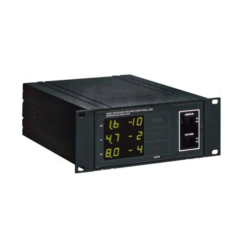
MKS 900 Series User manual

PDR900
Series 900 Vacuum Controller
RS232 / RS485
Operation Manual
P/N:
100017303
PDR900-12, Operation
Manual
Revision: C, October
2020

pg. 2
Notice
This product is intended for use by industrial customers and should be
serviced only by MKS trained representatives. The service manuals and
related materials are provided in English at no charge and are intended for
use by experienced technicians. It is the responsibility of the user to obtain
and assure the accuracy of any needed translations of manuals. If you
require assistance, contact the MKS Customer Service group. The MKS
Technical Support Group notifies users of record if safety-related upgrades
or new hazards associated with the product are identified.
Damage Requiring Service
Disconnect the product from all power sources and refer servicing to Qualified Service Personnel
under the following conditions:
a. When any cable or plug is damaged.
b. If any liquid has been spilled onto, or objects have fallen into the product.
c. If the product has been exposed to rain or water.
d. If the product does not operate normally even if you follow the operating instructions. Adjust only those
controls that are covered by the operation instructions. Improper adjustment of other controls may result
in damage and will often require extensive work by a qualified technician to restore the product to its
normal operation.
e. If the product has been dropped or the enclosure has been damaged.
f. When the product exhibits a distinct change in performance. This indicates a need for service.
Service and Warranty
Some minor problems are readily corrected on site. If the product requires service, contact the MKS
Technical Support Department at +1-833-986-1686. If the product must be returned to the factory,
request a Return Material Authorization (RMA) from MKS. Do not return products without first
obtaining an RMA. In some cases, a hazardous materials disclosure form may be required. The MKS
Customer Service Representative will advise you if the hazardous materials document is required.
When returning products to MKS, be sure to package the products to prevent shipping damage.
Shipping damage on returned products due to inadequate packaging is the Buyer's responsibility.
Customer Service / Technical Support:
MKS Global Headquarters
2 Tech Drive, Suite 201
Andover MA, 01810 USA
Phone: +1-833-986-1686
Email: insidesal[email protected]m
Visit our website at: www.mksinst.com
Warranty Information
MKS Instruments, Inc. provides an eighteen (18) month warranty from the date of shipment for new
MKS products. The MKS Instruments, Inc. general terms and conditions of sale provide the complete
and exclusive warranty for MKS products. This document is located on our web site at
www.mksinst.com, or may be obtained by a contacting an MKS customer service representative.

pg. 3
Proprietary Information
This document contains confidential proprietary information belonging to MKS Instruments, Inc. This information
is not for publication and has been provided by MKS on the condition that it not be copied, reproduced or
disclosed, either wholly or in part, to third parties without the expressed written consent of MKS Instruments, Inc.
The information contained in this document is subject to change without notice.
Copyright Information
© 2020 MKS Instruments, Inc. All rights reserved. Granville-Phillips® is a registered trademark of MKS
Instruments, Inc., and mksinst™, Mini-Ion™, DualTrans™, MicroPirani™, UniMag™, DualMag™,
QuadMag™ and Quatro™ are trademarks of MKS Instruments Inc. Windows® is a trademark of
Microsoft Corporation. All other trademarks and registered trademarks are the properties of their
respective owners.
No part of this work may be reproduced by any method including photocopying and recording or by any
information or retrieval system without written permission of MKS Instruments, Inc.
Table of Contents
Warranty Information ................................................................................................................................................. 2
Proprietary Information.............................................................................................................................................. 3
Copyright Information ................................................................................................................................................ 3
Table of Contents ...................................................................................................................................................... 3
General safety information ........................................................................................................................................ 4
Unpacking ................................................................................................................................................................. 5
Controller Installation ................................................................................................................................................ 5
Transducer Installation .............................................................................................................................................. 5
Electrical Connections .............................................................................................................................................. 8
Transducer Analog Output .................................................................................................................................... 8
Serial User Interface ............................................................................................................................................. 8
RS232 User Interface ............................................................................................................................................ 8
RS485 User Interface ............................................................................................................................................ 8
Set point Relay ...................................................................................................................................................... 8
Front panel .............................................................................................................................................................. 10
Alarm Indicator .................................................................................................................................................... 10
Set point Indicator ............................................................................................................................................... 10
Pressure Unit Indicator ........................................................................................................................................ 10
Menu Interface ........................................................................................................................................................ 10
View Menu .......................................................................................................................................................... 11
Leak Detector Tool .............................................................................................................................................. 12
Edit menu ................................................................................................................................................................ 12
Set Point .............................................................................................................................................................. 12
Alarm ................................................................................................................................................................... 13
Alarm Action ........................................................................................................................................................ 13
Alarm Test ........................................................................................................................................................... 13
Analog Output ......................................................................................................................................................... 13
Setup Menu ......................................................................................................................................................... 13
Calibration ........................................................................................................................................................... 14
Communication ....................................................................................................................................................... 14
Transducer Communication ................................................................................................................................ 15
Command Set ......................................................................................................................................................... 16
Maintenance ............................................................................................................................................................ 17
Trouble Shooting ................................................................................................................................................. 17
Changing Fuse .................................................................................................................................................... 17
Disposal (European Union only) .......................................................................................................................... 17
Menu Structures ...................................................................................................................................................... 18
View Menu Structure ........................................................................................................................................... 18
Tools Menu Structure .......................................................................................................................................... 19
Edit Menu Structure ............................................................................................................................................ 20
Setup Menu Structure ......................................................................................................................................... 21
Specifications .......................................................................................................................................................... 22
Accessories and replacement part numbers .......................................................................................................... 23

pg. 4
General safety information
Symbols used:
The first two symbols below are used throughout this manual to further define the safety concerns associated
with the product. The last two symbols identify other information in this manual that is essential or useful in
achieving optimal performance from the PDR900.
Caution: Risk of electrical shock. Failure to read message could result in
personal injury
Caution: Refer to manual. Failure to read message could result in personal
injury or serious damage to the equipment or both.
Failure to read message could result in damage to the equipment.
Calls attention to important procedures, practices or conditions.
The safety instructions should always be followed during installation and operation of the PDR900 Controller.
Otherwise, there is danger for electric shock and/or fire. Safety and installation instructions must be followed
for continued compliance to low-voltage directive EN61010-1 (IEC1010-1). Pass safety informationto all
users.
Safety Precautions:
Grounding. The PDR900 controller must always be properly grounded. Be sure that the
ac power line is grounded and use only the delivered 3 channel power cord or other
approved power cord. Before connecting any other inputs, be sure to connect the ac
power cord. Disconnect all other cables before removing the ac power cord.
Fuse change. If fuse change is required, remove all other inputs and finally ac power line.
Use only approved 5x20mm, 250Vac, 500mA, T fuse.
Explosive Environments. Do not use the PDR900 in presence of flammable gases or
other explosive environments.
Rack installation. When installed in rack the ac power should be controlled from a central
power supply.
Service and Repair. Do not substitute parts or modify instrument. Do not install
substituted parts or perform any unauthorized modification to the instrument. Return the
instrument to an MKS Calibration and Service Center for service and repair to ensure all
of the safety features are maintained.
CE Mark. The PDR900 complies with European standards for CE marking.

pg. 5
Unpacking
Before unpacking the PDR900 Controller, check all surfaces of the packing material for shipping damage.
Check to be sure the PDR900 package contains these items.
Part number
Description
PDR900-12-US
PDR900-12-EU
PDR900-12-UK
PDR900-12-JP
PDR900-12
Controller, RS232/485
1
1
1
1
100013463
Power cord US
1
-
-
1
100013464
Power cord EU
-
1
-
100013465
Power cord UK
-
-
1
100013726
Spare fuse 5x20mm, 500mA, T (1)
1
1
1
1
100010757
Relay connector
3
3
3
3
100013690
Mounting kit
1
1
1
1
100017303
Operation Manual
1
1
1
1
(1) Spare fuse is integrated in the fuse holder on the rear panel.
If any items are missing, contact MKS Customer Service at +1-833-986-1686 or your local MKS sales office or
distributor. Inspect for visible damage. If damage is found, notify the carrier immediately.
Transducers and cables
Transducer and transducer cable are ordered separately. Cables for connecting the PDR900 and
transducers are listed in the Accessories section.
Controller Installation
Do not use or install the PDR900 where following conditions occur:
- Temperatures lower than 0 oC or higher than 40 oC
- Corrosive or explosive gases
- Direct sunlight
- Altitude higher than 2000 m
The PDR900 can be built into a rack panel or be used as a free-standing unit. For built-in applications the
panel cut should be 92x92 mm. A mounting kit is included to mount the unit in a panel. For 19” rack mounting
(3U height) a ¼ rack (21HP) mounting panel is available. See the Accessories and Replacement Parts
section for ordering information.
The IP classification according to IEC 60529 is IP30 when used as a free-standing unit.
Transducer Installation
Refer to the transducer operation manual for detailed information on how to install the transducer.
Transducer operation manuals are available for download at www.mksinst.com.
Description
The PDR900 is a stand-alone, single-channel power supply and display
unit for use with the Series 900 transducers. The instrument provides
easy readout of pressure measurement and can also be used for setup
and configuration of transducer parameters.
The user interface gives a quick and easy access to all settings and
parameters through logically arranged menus.
The PDR900 is not only a readout and power supply unit; it also provides
leak detection tool and an audio alarm.
The controller communicates with the connected transducer via the digital RS232 or RS485 interface. The
digital communication between controller and transducer helps eliminate analog measurement noise.

pg. 6
Series 900 transducers
The Series 900 vacuum transducers are a complete suite of microprocessor based, stand-alone gauges, offering
a wide pressure measurement range from above atmosphere to high vacuum. Designed for system integration,
the transducers offer both analog and digital communication. All transducers have integrated set point relay for
process controlling.
The transducers incorporate MEMS (Micro Electro- Mechanical systems) based technologies, including
MicroPirani™ and Piezo sensors, combined with Mini Ion BA technology resulting in a broad product offering
for a wide range of customer applications.
901P Loadlock transducer
The 901P is a unique patented transducer designed specifically for the loadlock environment. It provides both
vacuum pressure measurement and atmospheric switching capabilities.
902B Piezo
The 902B Piezo provides an absolute measurement that is independent of gas type.
909AR Mini-Ion™
The 909AR offers pressure measurement from high vacuum to 1×10⁻² Torr and it’s based on hot cathode
ionization sensor.
910 DualTrans™
The 910 DualTrans is a dual sensor transducer, combining absolute piezo sensor and MicroPirani™ sensor.
The transducer measures over pressure down to 1×10⁻⁵ Torr.
925 MicroPirani™
The MicroPirani provides a measuring range from 1×10⁻⁵ Torr to atmosphere with 1 or 3 integrated set point
relays for process controlling.
971BUniMag™
The 971BUniMag™ is an Inverted Magnetron transducer providing a measuring range from 1×10⁻⁸ Torr
to 1×10⁻² Torr.
972B DualMag™
The 972 DualMag is an Inverted Magnetron transducer combined with a MicroPirani™ sensor. The transducer
provides a measuring range from 1×10⁻⁸ Torr to atmosphere.
974BQuadMag™
The 974BQuadMag is an Inverted Magnetron transducer combined with a MicroPirani™ sensor and an
differential piezo sensor. The transducer provides a measuring range from 1×10⁻⁸ Torr to atmosphere.
979 ATV
The 979 combines the MicroPirani and the Mini ion BA gauge to provide a wide measuring range.
999 Quattro™
The 999 Quattro™ is combines the MicroPirani and the Mini ion BA gauge, providing a wide pressure
measurement range and atmospheric switching capabilities.
The PDR900 Controller is compatible with the digital Series 900 transducers shown in this graph

pg. 7
Rear panel & connectors
4. Analog Out (8 pin DIN female)
5. Communication (9 pin DSUB male)
6. Transducer (15 pin HD DSUB female)
1. Power ON / OFF switch
Main supply on / off switch
2. Fuse holder
For main fuse change refer to page 16
3. Power in
Main supply voltage 100-240Vac, 50-60Hz,
25W
1. Transducer analog out+
2. Transducer analog out-
8. Chassis (Ground)
2. RS232 Transmit / RS485-
3. RS232 Receive / RS485+
5. Ground
1. RS485- / RS232 TXD
2. RS485+ / RS232 RXD
3. +24 VDC power output
4. Power Ground
5. Analog in+
6. Analog in -
7. Set point relay 1 control (Ground)
8. Set point relay 1 control
9. Not connected
10. Not connected
11. Set point relay 2 control
12. Set point relay 2 control (Ground)
13. Not connected
14. Set point relay 3 control
15. Set point relay 3 control (Ground)
7. Set point Relay (screw terminal connector)
1. Normally Open contact
2. Normally Closed contact
3. Common contact
1 2
3

pg. 8
Electrical Connections
Transducer Analog Output
The analog voltage output can be used for connection to external analog measuring equipment for pressure
reading and data logging. The analog output is provided by the transducer measurement circuit. The analog
out voltage vs. pressure curves varies with transducer type in use. For specific transducer voltage levels
refer to transducer operation manual.
The analog output must be connected to a differential input voltmeter or an analog to digital (A/D) converter
with a differential input in a system controller.
Do not connect the negative side of the analog output (pin 2) to the chassis / ground
(pin 4) or to any other ground. Measurement errors in the output voltage may be seen
due to the voltage drop from this current loop flow. The longer the cable, the worse the
error will be.
If the analog output is improperly connected, shorted to ground or heavily loaded, the
pressure transducer performance and consequently pressure reading can be affected.
Analog output connector and cables are available as accessories. Refer to Accessories and Replacement
Parts section.
Serial User Interface
The PDR900 is supplied standard with RS232 and RS485 user interface, allowing the setting or
change of transducer and controller parameters.
The serial interface uses following format: 8 data bit, 1 stop bit, no parity bit.
RS232 User Interface
The PDR900 is DCE (data communication equipment) and can be connected via straight cable to DTE
(data terminal equipment) such as a PC.
The serial communication does not use hardware handshake.
RS485 User Interface
RS485 is a network communication system that enables the user to communicate with several units on
the same communication line.
RS485 is a balanced communication system. There are 2 wires, other than ground, that are used to
transmit the digital signal. The PDR900 uses half duplex communication.
At high communication baud rates and when using long cable runs a 120 Ohm termination resistor
should be connected between pin 2 and 3 at the PDR900 RS485
connector.
Always use high quality shielded data cables for serial communication. Analog output
connector and cables are available as accessories. Refer to Accessory and Replacement
Parts on pages 27-29.
Set point Relay
The PDR900 has 3 mechanical relays that can be used for controlling external process equipment. The
power relays are controlled by the internal transducer relays and consequently only one relay is available
when using single set point transducers like the 902B and 925. Refer to the transducer and set point relay
table below.

pg. 9
The relay has Normally Open (NO) and Normally Closed (NC) contacts rated for 250Vac, 4A,
resistive load.
Wire size from 20 to 16 Ga (0.5 to 1.5 mm2 ) can be connected at the relay connectors which are
included with the PDR900 controller.
Do not connect any external sources to the relays pins on the transducer
connector when using the transducer together with the PDR900. Always use the
PDR900 relay outputs.
The relays can be activated either above or below set point value. The graphs below show the different
relays stages in either below or above configuration. The NC contact will always be closed in case of power
failure. For set point configuration refer to Edit Set point on page 14.
To prevent the relays from triggering during the power up cycle, each relay has a built-in delay function
before normal operation is resumed.

pg. 10
Front panel
1. 5 Digit LED display
2. Set point indicators
3. User interface LCD display
4. Keyboard
5. Pressure unit indicator
6. Alarm indicator
When the PDR900 controller is powered on it automatically searches for a connected transducer in RS232 and
RS485 mode. When the controller recognizes the connected transducer, it will initialize the menu interface and
only activate menus relevant for the current transducer type. The menu structure varies, depending on the
connected transducer type.
If no transducer is connected only a limited number of menus are available.
Searchin
g
for
Transducer . .
.
Alarm Indicator
The alarm indicator provides a red light when the low or high alarm limit is exceeded.
Set point Indicator
The multicolor 3 stage set point indicators provide a clear visual indication on the
set point relays status. When the relay is energized (C-NO) the set point
indicator illuminates green and when the relay is de-energized (C-NC) the
indicator will illuminate red. If the set point is disabled, the indicator will be off.
The set point indicators are updated via the digital interface and the built-in relays are updated
directly by the transducer relays. The update rates of the indicators are slower than the real
time relay state changing.
Pressure Unit Indicator
The pressure unit indicator provides a visual indication of the current display and transducer pressure unit
setup. The pressure unit can be changed in the setup menu. See Unit Setup on page 16.
LED Display
The 5-digit LED main pressure display provides a clear and bright readout of the measured pressure.
For multi sensor transducers the individual sensor readings can be displayed on the main display. To change
displayed sensor go to “Setup” and “Display”.
Menu Interface
The up and down arrow keys are used to scroll the arrow pointer through the current menu. The left arrow or
Set key is used to access the menu at the arrow pointer. The Esc key leaves the current menu and return to
the previous menu level.
When entering parameters like set point values the Set key stores the current or just entered value and returns
to the previous menu level. The Esc key returns to the previous menu level without storing the edited value.

pg. 11
View Menu
Graph
The graph display provides an analog bar graph reading of the displayed pressure. The graph scale fits the
measuring range of the connected transducer.
ıııı ıııııı ıııı ıııı ıııı ıııı
-
5
-
4
-
3
-
2
-
1
0+
1
+2
Pressure Display > Multi Reading
For transducers with multiple sensor, the Multi Reading menu provides reading of 2 different sensors at the
same time. Use the up and down arrow keys to scroll between sensor outputs.
MP = MicroPirani
PZ = Piezo
CMB = Combined
CC = Cold Cathode
HC = Hot Cathode
MP
:
7.
80
E+
2
PZ
:
1
.
00
E
-
1
CMB:
7.
6
2E+2
Pressure Display > Min/Max Display
The controller stores the lowest measured pressure and the highest measured pressure. The values are stored
in the non-volatile controller memory and consequently the values are retained when power is turned off.
The user can reset or clear the value by use of the reset menu. To allow the transducer to power up, there is a
30-second delay before logging min and max values.
Max.Pr.
7.80E+
2
Mi
n.
Pr
.
1
.
23
E
-
4
Transducer Information
The transducer information menu provides transducer model number, time on, serial number, part number,
firm/hardware versions, manufacturer, temperature and status.
Refer to transducer operation manual for available transducer information.
Model:
9
01P
LOADLOCK
Set point Status
The set point status menu provides an easy view of the set point relays status. When the relay is energized (C-
NO) the status is Set and when the relay is de-energized (C-NC) the status is Clear. The display provides the
status and the set point value for the relay
Set point
1:
Cl
ear
Value
:
1
.
23
E
-
4
Controller Information
The controller information menu provides controller serial number, firm/hardware versions and time
on.
Firmware
Versi
on
2.00
Time
on
00066
hours

pg. 12
Leak Detector Tool
The leak detector tool is a gas leak detector for detection of rough leaks by using a trace gas like helium. It
can be used in the pressure range from 1 to 400 Torr. The tool can only be used with MicroPirani™ based
transducers. The detectable leak rate depends on pumping speed, pressure range and chamber volume. For
Piezo/ MicroPirani™ based transducers the true differential measurement between the gas dependent
MicroPirani™ and the non-gas dependent Piezo is displayed. For only MicroPirani™ based transducer the
leak detector measures the measured pressure difference from the zero value. Successful use of the leak
detector requires a stable base pressure or condition.
Leak detector procedure:
1. Stabilize pressure in the range from 1 to 400 Torr.
2. Zero the leak detector.
3. Spray helium around the possible leak.
ıııı ıııııı ıııı ıııı ıııı ııı
0.1 1 10 100
If the bar graph increases a leak has been found. The bar graph scale represents the leak rate in an
arbitrary unit. When displaying the bar graph, the detector can be zeroed by use of the [SET] key.
Edit menu
Set Point
The PDR900 has 3 integrated set point power relays. The relays are controlled by the transducers set point
relays and consequently only one relay is available when using single set point transducers like the 902B
and 925.
The procedure for setting up set points is:
1 Select Edit
2 Select the set point to be set up or adjusted. Note that on the screens that follow the set point number will
be indicated on each parameter.
3 Enter set point value
4 Select set point direction
5 Enter set point hysteresis value, if other than +/- 10% of set point value is required.
6 Enable and assign set point
Set point Value
The set point value is the pressure either below or above which the set point relay will be energized.
Enter Pressure
4.00-3 Torr
Hysteresis Value
The hysteresis value is the pressure value at which the set point relay will be de-energized.
Enter Pressure
5.00-3 Torr
Direction
The set point direction configures if the relay is energized above or below the set point value.
Direction
BELOW
Enable set point
The enable set point enables or disables the set point. For multi sensor transducers like the 901P the set point
enable also configures the set point to a specific sensor either the differential piezo or absolute MicroPirani
sensor.
Enable
ON

pg. 13
The Series 900 transducers have an auto hysteresis setting of 10% of the set point
value. The hysteresis value is automatically changed whenever the set point value or
set point direction is changed. If hysteresis value other than 10% is required, always
set the set point value and set point direction before setting hysteresis value.
Alarm
The audio alarm can be used for sensing and warning of vacuum failures. If the pressure exceeds a specific
user defined high or low limit the audio alarm will provide a warning. The audio alarm can either be set as a
repeated or a momentarily audio signal. When the alarm is triggered the alarm indicator on the front panel will
be illuminated awhile the alarm limit is exceeded. The high and the low limits are set independently.
Enter Pressure
+1.00E+3 Torr
Enter Pressure
+9.00E-3 Torr
The alarm value and setup is independent of the transducer and stored in the controller non-volatile memory.
Alarm Action
The alarm can either be a single beep or beep continuously. The high and low alarm action can be configured
individually.
Action High
Loop
Alarm Test
The test buzzer function illuminates the front panel alarm indicator and provides 5 beeps.
When the pressure unit is changed, the High/Low alarm values will change
accordingly. The High/Low alarm values are not affected if the unit is changed by
the factory default command. They must be changed manually.
Analog Output
Some transducers have user configurable analog outputs. The Pressure Sensor menu selects which sensor to
use for the analog output. 1-5 corresponds to the PR1-PR5 output. Refer to transducer operation manual for
available transducer pressure readout.
The Curve Emulation menu, selects which equation the analog output voltage corresponding to the pressure will
follow. Refer to transducer operation manual for available equations.
Pressure Sensor
1
Curve Emulation
0
Cathode Power
To turn on/off power to a Cold- or Hot Cathode transducer, select Cathode Power from the Edit sub menu. The
power can then be set to on or off.
Cathode Power
ON
Setup Menu
Display Setup
The 5 digit LED display can be set to additional pressure outputs provided by the transducer. Refer to
transducer operation manual for available transducer pressure readout. For single sensor transducers like the
902B and 925 this menu is not relevant.

pg. 14
Display setup
PR1
Unit setup
Torr
Controller user com adr.
253
Controller user com baud
9600
Controller user com interface
RS232
Lock Setup
Disabled
Lock Controller
Disabled
Unit Setup
The PDR900 can provide readout in the pressure unit mbar, Torr and the SI unit Pascal. The pressure unit
setup is stored in the transducer and consequently, the change of the unit will also change the unit of the
controller to the unit of the transducer.
The unit cannot be changed when the data logger is active. Stop the current log
session to change the unit.
Calibration
The calibration menu enables adjustment of transducer measurement setup such as zeroing a transducer,
setting gas types or gas correction factors or performing an atmospheric cal.
Before executing any calibration commands always read the calibration procedure
described in the transducer operation manual. Failure to comply with the transducer
calibration procedure can result in large measurement errors.
All transducer calibration data is stored in the transducer memory and consequently changes to these values will
overwrite any existing transducer calibration values.
If the transducer is calibrated at an out of range pressure or the transducer has a malfunction the
display will provide an error message.
Code Protection—Lockout to Setup Menus
The PDR900 has a lock-out function to prevent any unauthorized access to the setup menus of the controller
and transducer parameters or to the entire menu interface. To activate the lock, enable lock setup or lock
controller, and enter the code. After confirming the code, the lock is activated.
Lock Setup
Lock Controller
If the lock function has been activated and the code has been lost, contact MKS customer service.
User Tag
The transducer user tag allows the user to identify or label the transducer (for example Main Chamber).
Factory Default
The factory default sets all parameter values for either the controller or the transducer to the factory
default settings, depending upon which option is selected. Refer to transducer operation manual for
transducer factory default values:
The factory default values for the controller are:
View Min.pressure
9.99E+09
View Max.pressure
-9.99E+09
Datalogger timer:
00:01:00
Datalogger control
Disabled
Datalogger source
PR1
Alarm high limit
1.00E+1
Alarm low limit
1.00E0
Alarm high action
OFF
Alarm low action
OFF
Communication
The PDR900 is equipped with both RS232 and RS485 user interface. The user communication interface
allows control of controller and transducer parameters as well as upload of data for storage and analyzing at
a remote PC.
Setup of User Interface
The user interface is configured at the Setup>Communication menu. The data format is 8 data bits, no
parity and one stop bit.
The controller communication setup can either be configured by use of the controller menu interface or by
use of the setup commands.
For user interface cable specification, refer to Electrical Connections section on page 8. To configure the user

pg. 15
communication interface, select the interface type, baud rate, and finally the address.
Transducer Adr-
Transducer Baud
Controller Adr-
Controller Baud
Interface Test
Controller Address
The controller address menu returns or sets the address of the controller for user communication interfaces.
Interface
The PDR900 controller is equipped with both RS232 and RS485 interface. The user communication type can be
viewed or configured at the interface menu.
Controller Comm
RS232 Interface
Controller Baud Rate
The communication speed is controlled by the baud rate. The higher baud value the faster communication.
The PDR900 user communication supports 2400, 4800, 9600, 19200, 115K baud rates (factory default
9600).
Test Interface
The test interface function will send a text string to the host computer and can be used for trouble shooting when
setting up the computer communication.
Sending Text
PDR900 Adr 253
Transducer Communication
The PDR900 can be used for configuration of transducer address and communication baud rate. The address
and baud rate values are stored in the transducer memory and consequently changing this setting will change
the setup of the transducer.
Transducer Address
The 900 Series transducers have an addressable user command set. The transducer address menu returns or
sets the address of the connected transducer.
Transducer Baud rate
The transducer baud rate menu returns or sets the communication baud rate for the connected transducer.
The lower the value, the slower communication speed. If a low baud rate value is used the update rate of
the display rating is also lower.

pg. 16
Command Set
The PDR900 command set allows the user to change controller parameters. Settings and parameters, like
set point values, set point configurations and calibration data, are stored in the transducers. These settings
can be changed via the PDR900 user interface. For changing transducer settings and parameters refer to
the command set and procedures described in the transducer operation manual.
Query and Command Syntax
Queries return current parameter settings; commands change the parameter setting according to the value
the user enters in the command syntax. Each query or command must begin with the attention character @
and end with the termination ;FF.
The command syntax has an address parameter that enables connection of multiple devices in a RS485
network. The address parameter is also included in non-network RS232 applications.
Address - ADC
The ADC command returns or sets the communication address for the controller. If multiple devices are
installed in a RS485 network, they can be addressed individually.
Values:
001 to 253 (default: 253)
Query
@254ADC?;FF
Query Response
@001ACK001;FF
Command
@001ADC!002;FF
Command Response
@002ACK002;FF
Baud Rate - BRC
Values:
Query
2400, 4800, 9600, 19200, 115K
Query Response Command
Command Response
@001BRC?;FF
@001ACK9600;FF @001BRC!19200;FF
@001ACK19200;FF
Factory Default - FDC
Command Command Response
@001FDC!;FF @001ACKFDC;FF
Firmware Version - FVC
Query Query Response
@001FVC?;FF @001ACK1.00;FF
Hardware Version - HVC
Query Query Response
@001HVC?;FF @001ACK1.00;FF
Serial Number - SNC
Query Query Response
@001SNC?;FF @001ACK000012345;FF
Time On - TIC
Query Query Response
@001TIC?;FF @001ACK000000024;FF
Alarm High Limit - ALH
Values: Two- or three-digit scientific notation
Query
Query Response
Command
Command Response
@001ALH?;FF
@001ACK1.00E-2;FF
@001ALH!1.00E-3;FF
@001ACK1.00E-3;FF
Alarm Low Limit - ALL
Values: Two- or three-digit scientific notation
Query Query Response Command Command Response
@001ALL?;FF
Action High - ACH
@001ACK1.00E-2;FF
@001ALL!1.00E-3;FF
@001ACK1.00E-3;FF
Values:
Query
OFF, SHORT, LOOP
Query Response
Command
Command Response
@001ACH?;FF
@001ACKSHORT;FF
@001ACH!LOOP;FF
@001ACKLOOP;FF
Action Low - ACL
Values:
Query
OFF, SHORT, LOOP
Query Response
Command
Command Response
@001ACL?;FF
@001ACKSHORT;FF
@001ACL!LOOP;FF
@001ACKLOOP;FF

pg. 17
Maintenance
In general, the PDR900 controller requires no maintenance other than proper installation and operation.
Refer to transducer operation manual for transducer maintenance.
Troubleshooting
Symptom
Possible cause / Remedy
Transducer not found on power up.
Searching for
transducer . . .
Check that transducer and transducer cable is compatible. Refer to
cable part numbers under Accessory section. Ensure cable screw
locks are fastened.
Error message when executing
calibration.
Zero adjustment
Transd Error . . .
Verify that the correct calibration procedure in the transducer
operation manual is followed. Possible transducer defect.
No light in display or indicators.
Check power switch is on. Check fuse at rear panel. Check AC
supply voltage 100-240VAC. Possible transducer defect.
Disconnect transducer and turn instrument on again. Possible
controller defect.
Missing user communication.
Check PC cable connection. Check computer baud rate and data
format match controller setup. Send test string from the
communication menu.
Changing Fuse
The PDR900 contains a main fuse protection. The fuse will blow if the instrument is
operated with higher voltage than specified or in case of instrument malfunction.
1. Turn the instrument off and remove all connectors and finally
remove the power line cord.
2. Open the fuse holder located at the power inlet.
3. A spare fuse is mounted in the fuse holder. Change the fuse only
with approved fuses with 500mA, T rating.
4. Connect the external connections starting with the power cord.
If the fuse blows again shortly after being changed, the instrument or the transducer has a malfunction
and should be returned to an MKS Service Center for repair.
Disposal (European Union only)
The PDR900 is manufactured according to the RoHS directive.
For the benefit of the environment, at the end of life of the PDR900, it should not be disposed
in the normal unsorted waste stream. It should be deposited at an appropriate collection point
or facility to enable recovery or recycling.

pg. 18
Menu Structures
View Menu Structure

pg. 19
Tools Menu Structure

pg. 20
Edit Menu Structure
Other manuals for 900 Series
1
This manual suits for next models
3
Table of contents
Other MKS Controllers manuals
Popular Controllers manuals by other brands

Klockner Moeller
Klockner Moeller SUCOS PS 316 installation instructions

UTC Fire and Security
UTC Fire and Security interlogix AL-1255 installation manual

SMC Networks
SMC Networks HEC002-A5 Operation manual

iNels
iNels GSB3-40 manual

TAOS
TAOS TSL2571 EVM2 Kit quick start guide

Generac Power Systems
Generac Power Systems PowerManager PM-PC manual