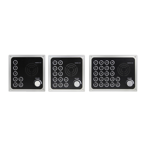
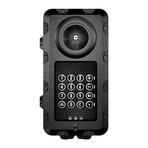
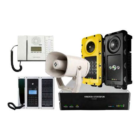
Zenitel VINGTOR STENTOFON ECP-AA1 Quick guide

Installation, Configuration & Operation
ECP-AA1 Intercom
A100K11789
TECHNICAL MANUAL

2 ECP-AA1 Installation, Configuration & Operation A100K11789
Contents
1Introduction......................................................................................................... 3
1.1 Document Scope...................................................................................................................3
1.2 Products.................................................................................................................................3
1.3 Publication Log......................................................................................................................3
1.4 Related Documentation.........................................................................................................3
2Installation & Mounting....................................................................................... 4
3Connectors & Power........................................................................................... 5
3.1 Connectors ............................................................................................................................5
3.1.1 Ethernet Connector .............................................................................................................................5
3.1.2 I/O Connector......................................................................................................................................5
3.2 Power.....................................................................................................................................5
3.3 Connection to Emergency Break...........................................................................................6
3.4 Connection to CCTV System.................................................................................................6
4Configuration....................................................................................................... 7
4.1 Initial Setup............................................................................................................................7
4.2 Audio Settings .......................................................................................................................8
4.3 I/O Settings............................................................................................................................9
4.4 Output Settings......................................................................................................................10
4.4.1 CCTV Interface....................................................................................................................................10
4.4.2 General Settings..................................................................................................................................11
4.5 Call Button Settings...............................................................................................................13
4.5.1 Ringlist Settings...................................................................................................................................14
4.6 SIP Configuration ..................................................................................................................15
5Operation............................................................................................................. 16
3 ECP-AA1 Installation, Configuration & Operation A100K11789
1 Introduction
1.1 Document Scope
This document describes the installation, configuration and operation of the ECP-AA1 Intercom.
1.2 Products
Item Number
Item Name
1008192011
ECP-AA1 Intercom
1.3 Publication Log
Revision
Date
Author
Status
1.0
18.5.2016
HVD/HKL
Published
1.1
16.9.2019
HKL
New doc no. A100K11789
1.4 Related Documentation
Doc. no.
Documentation
A100K11194
Turbine IP Intercoms Technical Manual

4 ECP-AA1 Installation, Configuration & Operation A100K11789
2 Installation & Mounting
The ECP-AA1 is flush-mounted using 4 screws of type:
•M4x16 DIN 7991 A4 –Flat Head Socket Cap Screw, Stainless Steel A4 DIN7991
•Length as required

5 ECP-AA1 Installation, Configuration & Operation A100K11789
3 Connectors & Power
3.1 Connectors
The ECP-AA1 has 2 connectors located at the bottom of the unit.
3.1.1 Ethernet Connector
Type: M12, D-coded, Female, 4-pin
1
TD+
2
RD+
3
TD-
4
RD-
3.1.2 I/O Connector
Type: M12, A-coded, Female, 8-pin
1
+5V DC
2
GND
3
I/O 1
4
I/O 2
5
I/O 3
6
Relay –Common
7
Relay –NC
8
Relay –NO
3.2 Power
The ECP-AA1 is powered through the Ethernet connector via Power over Ethernet (PoE). The
Ethernet connector is located at the bottom of the unit.

6 ECP-AA1 Installation, Configuration & Operation A100K11789
3.3 Connection to Emergency Break
The emergency break provides a clean contact to the ECP-AA1. Its purpose is so that an
emergency call is made as soon as the emergency break handle is operated.
Procedure
•Connect the clean contact between pins 2 and 3 on the I/O connector.
3.4 Connection to CCTV System
The ECP-AA1 provides a clean contact to the CCTV system. Its purpose is to send a trigger to the
CCTV system when a call is made from the ECP-AA1.
Procedure
•Connect the CCTV trigger input between pins 6 and 8 on the I/O connector.

7 ECP-AA1 Installation, Configuration & Operation A100K11789
4 Configuration
4.1 Initial Setup
The ECP-AA1 is delivered with factory default settings. By default, the unit’s IP settings are
configured according to DHCP.
To configure the unit:
1. Press the call button on the unit for it to speak its IP address
2. Ensure that the IP address of your PC is in the same range as that of the station IP
address.
3. Access the station by logging into the web interface using a standard web browser on
your PC
4. In the browser’s address bar, enter the station IP address and press the ENTER key
•The station login page will be displayed.
5. Click Login
6. Enter the default User name: admin
7. Enter the default Password: alphaadmin
8. Select Station Main > Main Settings
9. Under Station Mode select Use SIP
10. Under Product Model And Accessory select Kit
11. Depending on system requirements, set the IP Settings to DHCP or Static IP. In the
latter case, fill in the network details as required
12. Click Save
13. On the new page, click Apply
The unit will now reboot.

8 ECP-AA1 Installation, Configuration & Operation A100K11789
4.2 Audio Settings
Normally no changes are required to be made to the audio settings, but depending on the specific
circumstances where the unit is installed, minor adjustments may be needed.
•Select SIP Configuration > Audio Settings
On this page it is possible to set:
•Speaker Volume
•Microphone Sensitivity
•Noise Reduction Level
Furthermore, it is possible to select different algorithms for the Conversation Mode.
Note that due to the close proximity of the microphone and speaker it may be necessary to select
Robust Duplex as Conversation Mode if either the speaker level or the microphone sensitivity is
increased from that of the default setting.

9 ECP-AA1 Installation, Configuration & Operation A100K11789
4.3 I/O Settings
•Select SIP Configuration > I/O Settings
Under Configuration set the following values for the I/O Pins:
-I/O Pin 1: Input 1
-I/O Pin 2: Input 2 or Output 2 –depending on the application for which this I/O will be used
-I/O Pin 3: Input 3 or Output 3 –depending on the application for which this I/O will be used
-I/O Pin 4: Input 4
-I/O Pin 5: Output 5
-I/O Pin 6: Output 6
•Click Save
Although the ECP-AA1 will not use these settings until after a reboot, it is not necessary to reboot
at this stage.

10 ECP-AA1 Installation, Configuration & Operation A100K11789
4.4 Output Settings
•Select SIP Configuration > Relay Settings
4.4.1 CCTV Interface
For Choose Relay To Configure:
•Select Relay 1
Under Configuration set the following values:
-Outgoing Ringing: On
-Idle: Off
•Click Save

11 ECP-AA1 Installation, Configuration & Operation A100K11789
4.4.2 General Settings
For Choose Relay To Configure:
•Select Output 5
Under Configuration set the following values:
-Outgoing Ringing: Slow flash
-Outgoing Call: Off
-Idle: Off
•Click Save

12 ECP-AA1 Installation, Configuration & Operation A100K11789
For Choose Relay To Configure:
•Select Output 6
Under Configuration set the following values:
-Outgoing Call: On
-Idle: Off
•Click Save

13 ECP-AA1 Installation, Configuration & Operation A100K11789
4.5 Call Button Settings
Both the call button on the unit and the emergency break input are set up as a call button.
•Select SIP Configuration > Direct Access Key Settings
Assuming that the call button should call a fixed number:
•Enter the number to be called in the field Value for both Input 1 and Input 4
•Make certain that the Function (in call) settings for both inputs are set to Do Nothing
•Click Save

14 ECP-AA1 Installation, Configuration & Operation A100K11789
4.5.1 Ringlist Settings
Optionally it is possible to make the ECP-AA1 call numbers in sequence until the call is accepted.
If this is the requirement, make the settings as shown below:
•Under the parameter Option select Ringlist 1 for both Input 1 and Input 4
•Under Ringlist Settings and Ringlist 1 define up to 14 numbers which will be called in
sequence
•Check the Call Until Answer box
•In the Ringing Time field enter a maximum time in seconds before the next number in
the list should be called
•Click Save

15 ECP-AA1 Installation, Configuration & Operation A100K11789
4.6 SIP Configuration
For the ECP-AA1 to be able to register to a SIP server, the correct SIP settings must first be done.
•Select SIP Configuration > SIP Settings
•Enter values for : Display Name, Directory Number (SIP ID), Server Domain (SIP),
Authentication User Name
•Enter values in other fields as may be required by the SIP server
•Click Save
•Click Apply
The ECP-AA1 will now reboot and all settings that have been made in the previous sections
will take effect when the unit is up and running again.

16 ECP-AA1 Installation, Configuration & Operation A100K11789
5 Operation
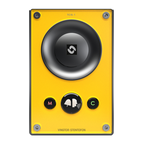
The ECP-AA1 Intercom is a user-friendly Emergency Call Point with a single call button.
To make a call:
•Press the call button
oThe red illumination ring around the call button will start flashing
oA ring-back tone will be audible from the speaker
When the operator accepts the call:
oThe green LED will be lit, indicating that 2-way communication is now possible
oThe ring-back tone will cease
oSpeak into the microphone to communicate with the operator
When the operator terminates the call:
oThe unit will revert to its idle state
Speaker
Microphone
Call Button
Indication LED

The WEEE Directive does not legislate that Zenitel, as a ‘producer’, shall collect ‘end
of life’ WEEE.
This ‘end of life’ WEEE should be recycled appropriately by the owner who should use
proper treatment and recycling measures. It should not be disposed to landfill.
Many electrical items that we throw away can be repaired or recycled. Recycling items helps to
save our natural finite resources and also reduces the environmental and health risks associated
with sending electrical goods to landfill.
Under the WEEE Regulations, all new electrical goods should now be marked with
the crossed-out wheeled bin symbol shown.
Goods are marked with this symbol to show that they were produced after 13th
August 2005, and should be disposed of separately from normal household waste so
that they can be recycled.
A100K11789
ZENITEL PROPRIETARY. This document and its supplementing elements, contain Zenitel or third party information which is proprietary and confidential. Any disclosure, copying, distribution or
DOC NO.
customer.service@zenitel.com
www.zenitel.com
Zenitel Norway AS
Table of contents
Other Zenitel Intercom System manuals

Zenitel
Zenitel Phontech CIS 3100 Instruction Manual

Zenitel
Zenitel ITSV-2 User manual

Zenitel
Zenitel Vingtor Stentofon ITSV-3 User manual

Zenitel
Zenitel IPDM-V2_P User manual

Zenitel
Zenitel Vingtor Stentofon AlphaCom User manual

Zenitel
Zenitel Turbine Compact IP + Guide

Zenitel
Zenitel TCIS-1 Guide

Zenitel
Zenitel VR3G-1 Guide

Zenitel
Zenitel TEIV+ User manual

Zenitel
Zenitel EAPFX-1-V2 Instruction Manual