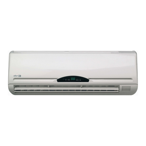
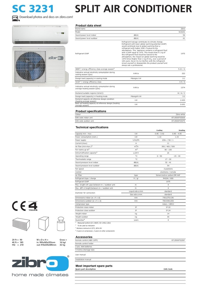
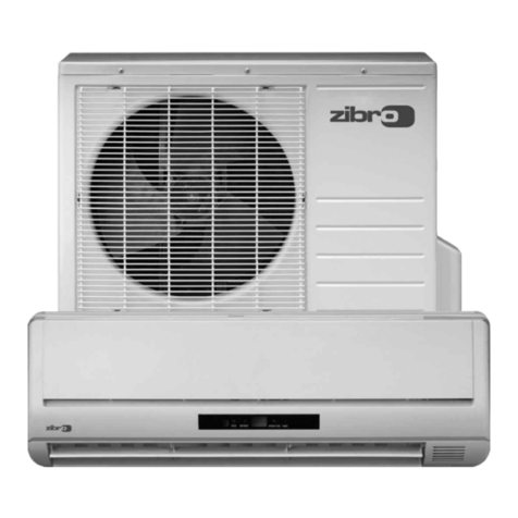
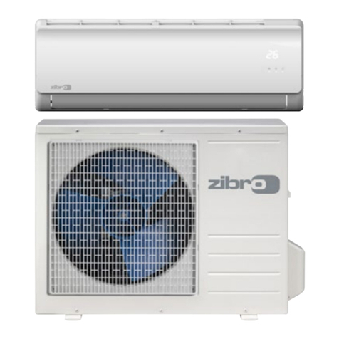
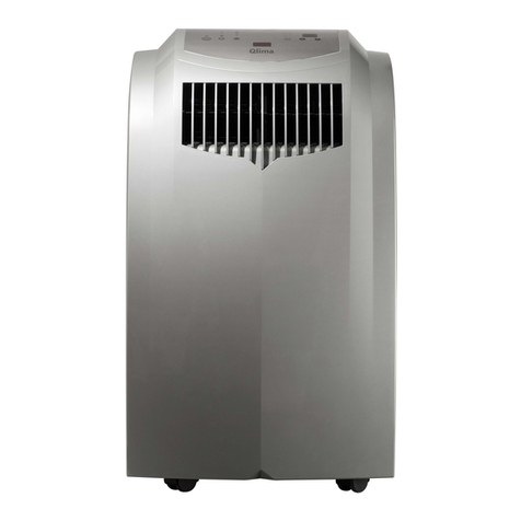
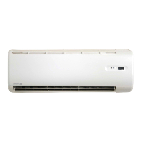
Zibro S1735 User manual

3%26)#%-!.5!,
2//-!)2 #/.$)4)/.%2
3
3
#/.4%.43
63(&,),&$7,21
)81&7,216
6(59,&()81&7,21(;3/$1$7,21
23(5$7,21'(7$,/6
7528%/(6+227,1**8,'(
3(5)250$1&(&859(',$*5$0
(/(&75,&&,5&8,7',$*5$0
6&+(0$7,&',$*5$0$1'3&%·6
3$576/,673&%
6(0,&21'8&725/($','(17,),&$7,21
6(0,&21'8&7253,1)81&7,21
7+(50,67255(6,67$1&(&+$57
(;3/2'('9,(:,1'22581,7
(;3/2'('9,(:287'22581,7
3$576/,67,1'22581,7
3$576/,67287'22581,7

SPECIFICATION
– 1 –
Unit
BTU/hCooling Capacity
INDOOR OUTDOOR
–
BTU/hHeating Capacity –
L/h
phase
Moisture Removal –
Power source
Single
V230
Hz 50
OUTLET
Airflow Method
SIDE VIEW TOP VIEW
INTAKE
m/min
Air circulation (at High) Cooling ;
Heating ;
W
Electrical Data
Input
Running Current
Starting Current
Inner diameter
Length
Cooling ;
Heating ; –
–
ACooling ;
Heating ; –
–
A
inch
Piping Connection Port (Flare piping) L L
inch G G
inch
Pipe Size (Flare piping) inch
mm
Drain hose
Length
Height
Width
Depth
Number of core-wire
Power Cord
–
m–
m–
core-wire/ 1 mm –
mm
Dimensions mm
mm
kg
Net Weight
3
2
; Half Union 1/4''
; Half Union 3/8''
L (liquid side) ; 1/4''
G (gas side) ; 3/8''
; 2-way valve 1/4''
; 3-way valve 3/8''
L (liquid side) ; 1/4''
G (gas side) ; 3/8''
S 1731 S 1731
9,000(4,400-10,600)
11,000(4,800-12,300)
1.6
4.1
7.8
8.6
760
860
3.6
4.1
14
0.6
1.4
265
795
192
7.8
530
780
277
30.0

SPECIFICATION
– 2 –
Unit
Air Circulation
INDOOR OUTDOOR
Cross-flow Fan Propeller Fan
S 1731 S 1731
18 21
Induction (4-pole) Induction (6-pole)
W
Heat Exchanger 18.1FPI 19.5FPI
Capillary Tube
Plate fin configuration,forced draft
Refrigerant Control Device g (oz)
Refrigerant (R410A )
–850(30.0)
–
Thermostat
Air Filter
Parts Provided
Electronic Control
Type
Motor Type
Rated Output
–
Mold-proof –
Specifications are subject to change without notice.
1 Mounting plate
2 Remote controller
3 Battery (2 pcs.)
4 Remote controller holder
5 Screw cap (2 pcs.)
6 Drain elbow
7 Vibration proof rubber (4 pcs.)
8 Air clean filter×2
Bamboo Charcoal/Photo-catalytic anti-odor filter×1
Bio-photo Catalytic filter×1
9 Gum bushing
Timer –
Real time dual ON/OFF
7-hour OFF

SPECIFICATION
– 3 –
Unit
BTU/hCooling Capacity
INDOOR OUTDOOR
–
BTU/hHeating Capacity –
L/h
phase
Moisture Removal –
Power source
Single
V230
Hz 50
OUTLET
Airflow Method
SIDE VIEW TOP VIEW
INTAKE
m/min
Air circulation (at High) Cooling ;
Heating ;
W
Electrical Data
Input
Running Current
Starting Current
Inner diameter
Length
Cooling ;
Heating ; –
–
ACooling ;
Heating ; –
–
A
inch
Piping Connection Port (Flare piping) L L
inch G G
inch
Pipe Size (Flare piping) inch
mm
Drain hose
Length
Height
Width
Depth
Number of core-wire
Power Cord
–
m–
m–
core-wire/ 1 mm –
mm
Dimensions mm
mm
kg
Net Weight
3
2
; Half Union 1/4''
; Half Union 3/8''
L (liquid side) ; 1/4''
G (gas side) ; 3/8''
; 2-way valve 1/4''
; 3-way valve 3/8''
L (liquid side) ; 1/4''
G (gas side) ; 3/8''
S 1735 S 1735
11,300(4,800-11,900)
12,500(4,800-14,300)
2.0
4.6
9.3
9.8
970
880
4.6
4.2
14
0.6
1.4
265
795
199
8.9
530
780
277
30.0

SPECIFICATION
– 4 –
Unit
Air Circulation
INDOOR OUTDOOR
Cross-flow Fan Propeller Fan
22 21
W
Heat Exchanger 19.5FPI 19.5 FPI
Plate fin configuration,forced draft
Refrigerant Control Device g (oz)
Refrigerant (R410A )
–850(30.0)
–
Thermostat
Air Filter
Electronic Control
Type
Motor Type
Rated Output
–
Mold-proof –
Specifications are subject to change without notice.
1 Mounting plate
2 Remote controller
3 Battery (2 pcs.)
4 Remote controller holder
5 Screw cap (2 pcs.)
6 Drain elbow
7 Vibration proof rubber (4 pcs.)
8 Air clean filter×2
Bamboo Charcoal/Photo-catalytic anti-odor filter×1
Bio-photo Catalytic filter×1
9 Gum bushing
Timer –
Real time dual ON/OFF
7-hour OFF
Parts Provided
Induction (4-pole) Induction (6-pole)
Capillary Tube
S 1735 S 1735

– 5 –
REMOTE-CONTROL TRANSMITTER
ON/OFF
Operation mode selection
COOL
DRY
HEAT
AUTOMATIC
CIRCULATION
Air flow selection
AUTOMATIC
HIGH
MEDIUM
LOW
Negative Ion
Room temperature setting
16°C〜30°C
Timer operation selection
CONTINUOUS operation
OFF
ON
Sleep
Timer / time setting
Operation stops at the set time
(OFF timer)
Operation starts at the set time
(ON timer)
0.5〜7.0hours(Sleep timer)
Air flow direction control
Auto angle selection
Auto swing mode
Manual mode
INDOOR UNIT
INDOOR UNIT
Sensing the room temperature
Room temperature sensor (thermistor)
Time delay safety control
Restarting is inhibited for approximately
3 minutes.
Indoor fan speed control
High, Med, Low
Operation indication lamps (LED)
POWER (GREEN or RED)
Lights up green during operation.
Lights up red when negative ions are
generated.
TIMER (YELLOW)
Timer in operation
OPERATE (GREEN)
Outdoor unit operate
Dry operation mode
Automatic fan speed control
Room temperature control
Maintains the room temperature in
accordance with the setting temperature.
Deice (defrost) control
Deicing operation automatically starts
when the heating efficiency is declined by
the ice formed in the outdoor unit.
After deicing operation, heating operation
automatically starts with “Hot start
function.”
FUNCTIONS

– 6 –
OUTDOOR UNIT
Inverter control
Inverter control reduce the ON/OFF
times of compressor,so can keep the
room temperature changeless during
operation.
Electricity consumption
Inverter control can operate with less
electricity consumption than normal air
conditioner.
3 min. forced operation control
Once the compressor is activated, it
does not stop for 3 minutes.
In case of termination of this operation,
push the ON/OFF button on remote
controller.
Hot-start control (heating)
The indoor fan stops until the evaporator
piping temperature will be reached.
Anti-freezing control for the
evaporator
Compressor will be stopped when the
evapolator’s piping temperature is below
2℃for one minute.
Compressor will be restarted when the
evaporator’s piping temperature is above
2℃.
Airflow direction control
When ON/OFF BUTTON is pressed, the
vertical louver will move to the adequate
positions for each operation automatically.
Manual operation.
The louver starts vertical swing with a
push of the LOUVER BUTTON.
Push the LOUVER BUTTON once again
to stop the louver at the desired position
while swinging.
Auto recovery function
If there is any power failure during
operation, operation status before power
failure is memorized.
3〜4 minutes after power recovery, the
unit restarts automatically with previous
operation status memorized.
(3〜4 minutes is protective time for
compressor.)
Attention
Because of Auto recovery function, if
shutting off the power supply during
operation, the unit may restart
irrespective your intention when turning
on the power supply next time.
If the unit is not to be used for a long
time, shut off the power supply after
terminating all operation with remote
controller.
FUNCTIONS

– 7 –
EMERGENCY AND TEST OPERATION
Emergency Operation
•Use this operation only when the remote controller is out of order or lost.
•When the emergency operation switch is pressed, beep starts once, which
means the start of this operation.
•In this operation, the system automatically selects the operation modes, cooling
(or heating when available) according to the room temperature, as follows.
•It is not possible to operate in dry mode.
Test Operation
Test operation switch is same as emergency one.
•Use this operation only for testing the performance of the machine in
the condition where the room temperature is less than 16°C.
•Continue to press the test operation switch for more than 5 seconds.
After you hear twice beep, release your finger from the switch
: the cooling operation starts with the air flow speed “HI.”
•If the test operation switch is pressed more than 10 seconds, it doesn’t
work.
•After 30 minutes, test operation ends automatically.
SERVICE FUNCTION EXPLANATION
J1
Soldering
J1
Temperature
ABOVE 23℃
BELOW 23℃
COOLING
HEATING
26℃
23℃
CONTINUOUS
CONTINUOUS
AUTOMATIC
AUTOMATIC
Operation Designated
mode temperature Timer mode Air flow
HOW TO RELEASE EMERGENCYAND TEST OPERATION
•In case of releasing during those operations, you can either push emergency operation switch once more or
apply operation using remote control.
You will hear a beep sound and emergency/ test operation is released.
•If you release the operation by remote control, operation will continue as setting of the remote control
automatically.
INTERFERENCE PREVENTION OF SIGNALS FROM THE REMOTE CONTROLLER
When two indoor units used in the same room, interference of the signals may happen. To avoid this, alternative
signal model B can be selected by the following. (Ex-factory setting is modeA)
•Remote controller side : Have “J1” on the PC board short-circuited by soldering.
•Indoor unit side : Cut “R13” on the PC board.
Twice beep
Beep

– 8 –
TIMER OPERATION
ON Timer operation
•Press the ON/OFF switch. Right after replacing new batteries, set the present time in advance.
•Set the “ON Time” : Press the “TIMEADJ” button twice.
Adjust the time with the “ , ” button.
Press the “TIME ADJ” button twice.The setting of “ON Time” is completed and the present time appears on the LCD.
•Set the “ON Timer” : Press the Timer fixing button “ON”.
OFF Timer operation
•Press the ON/OFF switch. Right after replacing new batteries, set the present time in advance.
•Set the “OFF Time” : Press the “TIMEADJ” button 3 times.
Adjust the time with the “ , ” button.
Press the “TIME ADJ” button once.The setting of “OFF Time” is completed and the present time appears on the LCD.
•Set the “OFF Timer” : Press the Timer fixing button “OFF”.
Sleep Timer operation
•Press the “SLEEP” button during the operation.
•Set the operating period by pressing the “SLEEP” button until the period designated appears on the LCD.
Timer Cancellation
•ON/OFF Timer : Press the Timer fixing button “ON”(On Timer) and/or “OFF”(Off Timer) once again.
•Sleep Timer : Press the “SLEEP” button until the operating period on the LCD disappears.
AIRFLOW DIRECTION CONTROL
Vertical adjustment
When ON/OFF switch is pressed, the vertical louver will move to the adequate positions for each operation
automatically.
Swing of air flow
If air flow direction switch is pressed once, the vertical louver will move within the range of figures.
Fixing the flow direction
If air flow direction switch is pressed again, the vertical louver will be fixed and that position is memorized.
From the next operation the louver will be set at previous position automatically.
Notes :
•In Swing Mode, the louver automatically moves up and down within the certain range, as the illustration below.
•There is two different ranges of louver swinging; one is of cooling & dry mode operation and the other is of
heating operation.
OPERATION DETAILS
Level
Approx.10 degrees
Approx.65 degrees
Standard Position
Approx.10
Approx.50 Approx.65
(Cooling/Dry)
(Heating)
degrees
degrees de
g
rees
Level
Swing of Air Flow
Cooling
Dry
Heating

– 9 –
OPERATION DETAILS
TIME DELAY SAFETY CONTROL FUNCTION - FOR PROTECTION OF COMPRESSOR
•Compressor will not restart, in any operation modes, for 3 minutes after its stop.
•Compressor does not stop during the first ★1 seconds of its operation even if the room temperature reaches
to the designated temperature, except changing setting temperature.
S 1731
S 1735
★1
120
180
★2
40
60
★3
68.0Hz
72.0Hz
★4
32.0Hz
32.0Hz
-1.3˚C
MAX MAX
★3★3
MIN★4MIN★4
0.7˚C
0Hz
Frequency of
Designated
compressor
temperature
Room temperature
COOLING MODE OPERATION
•The compressor will stop when operational frequency reached the minimum frequency and that condition has
been kept for ★1 seconds and the room temperature becomes 1.3℃ lower than it was set.
•The compressor will re-start when room temperature becomes 0.7℃higher than it was set.
•The operational frequency will be set every ★2 seconds of operation.
The operational frequency setting will be calculated based on the deviation of the room temperature and the
set temperature on one end and the deviation factor at the time of previous setting on another.
Model

– 10 –
OPERATION DETAILS
DRY MODE OPERATION
•The compressor will stop when operational frequency reached the minimum frequency and that condition has
been kept for ★1 seconds and the room temperature becomes 1.3℃ lower than it was set.
•The compressor will re-start when room temperature becomes 0.7℃higher than it was set.
•The operational frequency will be set every ★2 seconds of operation.
The operational frequency setting will be calculated based on the deviation of the room temperature and the
set temperature on one end and the deviation factor at the time of previous setting on another.
Indoor fan Selected speedStop Super low
3min.
MAX MAX
0
Hz
Frequency of
compressor
Designated
temperature
Room temperature
★3★3
MIN★4MIN★4
Selected speed
-1.3˚C
0.7˚C
★1
120
180
★2
40
60
★3
68.0Hz
72.0Hz
★4
32.0Hz
32.0Hz
S 1731
S 1735
M
ode
l

– 11 –
OPERATION DETAILS
★2
40
60
★1
120
180
★3
74.0Hz
80.0Hz
★4
32.0Hz
32.0Hz
+3.0
29˚C
33˚C
15˚C
MAX
★3
MAX
★3
MIN★4MIN★4
+5.0
0Hz
Super
low
Frequency of
compressor
Designate Fan blow
Low Low
Low Super low Designated
Fan blow
Designated
temperature Room temperature
Stop
Temperature,
indoor heat
exchanger
Indoor fan
20sec.
S 1731
S 1735
HEATING MODE OPERATION
•The compressor will stop when operational frequency reached the minimum frequency and that condition has
been kept for ★1 seconds and the room temperature becomes 5.0°Chigher than it was set.
•The compressor will re-start when room temperature becomes 3.0°C higher than it was set.
•The operational frequency will be set every ★2 seconds of operation.
The operational frequency setting will be calculated based on the deviation of the room temperature and the
set temperature on one end and the deviation factor at the time of previous setting on another.
Model

– 12 –
★1
58.0Hz
58.0Hz
★2
74.0Hz
80.0Hz
S 1731
S 1735
Compressor
Outdoor fan
4way valve
ON OFF OFF
ON
ON
ON
ON
48.0Hz
2min. 1min.
50sec.
50sec.
53sec.
Max 12min.
53sec.
sec.
10
2min.
-1˚C
8˚C
Defrosting starts Defrosting stop
Temperature of
outdoor heat exchanger
★1★2
DEFROSTING OPERATION(FOR OUTDOOR UNIT HEAT EXCHANGER)
•Defrosting operation is controlled by the temperature of outdoor heat exchanger sensed by the thermistor and
the timer switch.
•Defrosting operation starts when the both of the following conditions are met at the same time.
a) 34 minutes’ of continuous run of the compressor after the start of heating operation or after the completion
of previous defrosting operation.
b) the temperature of the outdoor heat exchanger stays lower than -1°C continuously for two minutes.
•Defrosting operating is called off if either of the following conditions is met.
a) The temperature of outdoor heat exchanger rises to 8°C while 4-way-valve is ON.
b) 12 minutes has passed since compressor turned OFF.
OPERATION DETAILS
Model

– 13 –
COMPRESSOR STARTING SEQUENCE
OPERATION DETAILS
10Hz
Start T1 T2 T(Max)T3 T4 T5
F2
F3
F4
F5
Max
Min
Model Time T2
Frequency F2
Cooling 48Hz
T3 T(Max)
F3 Max
58Hz 68Hz
T4
F4
-
Heating 48Hz
1.5min.
1.5min.
58Hz 74Hz
1min. 30min.
1min. 40min.
-
-
-
T5
F5
54Hz
-
Min
32Hz
64.7Hz
limitless
limitless
32Hz
-
-
Cooling 48Hz 58Hz 72Hz -
Heating 48Hz
1.5min.
1.5min.
58Hz 80Hz
1min. 30min.
1min. 40min.
-
-
-
66.7Hz 32Hz
69.3Hz
limitless
limitless
32Hz
-
-
T1: Forced rotating to reach 10Hz
F2,F3: Forced frequency for lubricant back
S 1731
S 1735

– 14 –
TROUBLESHOOTING GUIDE
FOR YOUR SAFETY USE
IN: indoor unit OUT: outdoor unit
●For the safety and proper use and handling of the product, please read and follow the instructions carefully.
●The meaning of the marks below are as follows.
●Never remodel appliance.
Use designated parts or accessories to avoid accidents.
●In case of gas leakage, not only refill the required amount of the refrigerant gas but
also find out the gas leakage point and mend it. If the service work has to be
suspended before mending the leakage points, be sure to collect the refrigerant
gas in the outdoor unit by using pump then fasten the service ports to avoid any
further leakage. Poisonous gas may be generated when the leaked refrigerant is
exposed to fire.
●Clean the pins of the plug and insert the plug completely into the outlet.
●Be sure to change the cable if it is damaged.
Do not use damaged cable.
●Do not use power supply cord extended or connected in halfway.
●Be sure to put the units to earthing works.
●Be sure to check the insulated resistance, more than 1MΩ.
Warning
※The combinations of three LED indicators (ON/Flashing/OFF) provide the self-diagnosis information as most of them shown in
the trouble shooting guide.
[Note1]
Check
Point
Check
Point
●Be sure to take off the plug when servicing.
It may cause the risk of electric shock.
●If leakage of refrigerant occur in the installation, ventilate a room.
If the leaked refrigerant is exposed fire, poisonous gas may be generated.
Danger
●Boosting capacitor make the control box assembly (OUT unit) high voltage.
Make the capacitor discharge enough when servicing. Otherwise will be struck
by electricity.
Improper use will cause the significant risk of death or serious injury of the user.
Danger
Warning Improper use may cause the risk of death or serious injury of the user.
Caution ProhibitedHigh Voltage
Strict enforcement Connect the earthing cable
Off the Plug
●Please refer the marks below.
High Temperatare
Discharge electricity of the capacitor by making short circuit firstly. Then check the capacitor by tester.
Be sure to set up the tester for the measurement of bigger resistance.

– 15 –
TROUBLESHOOTING GUIDE
INDICATION LAMP
Micro computer self-diagnose the points of the troubles and inform it by the combination of the status (On, Flush, or
Off) of three lamp indicators on the front panel of the indoor unit.
ALARM
INDICATION TIME APPEARANCE, PORTION, PARTS
SEEMED WRONG
MOMENTARY STOP OF POWER
(IN CASE OF LIGHTNING)
DROP OF POWER VOLTAGE
check the plug inserted into the outlet and the power supply
emergency operation (display of remote controller is faint or not)
check the electric continuity by tester
emergency operation
other than described above
15 sec. later after main power on, if alarm indication appears,
IN PCB (main) should be replaced
METHOD OF CHECK
(press the ON/OFF button of remote controller in case of reset)
POWER
(green) TIMER
(yellow)
OPERATION
(green)
INDICATION LAMP
OFF OFF OFF
IN, OUT do not work at all
FLASHING
OFF OFF
OFF
FLASHING
ON ON
ON
ON
FLASHING
ON ON
FLASHING
FLASHING
ON OFF
alarm indication appears
immediately when press
operation switch
OFF OFF
FLASHING
FLASHING
OFF
FLASHING
IN, OUT don’t work at all,
and after 20 sec., operation
lamp is flashing (2 min. in
case of power on)
normal lamp indication
turn alarm when
something is wrong with
IN, OUT
error of transmission
CT disconnection
OFF
FLASHING
OFF
FLASHING FLASHING
OFF
OFF
or
30 〜40 min. later after
compressor start, the yellow
lamp is flashing and IN,
OUT stop running
sensor discharge operate
because temperature of
discharge tube beyond
100°C, or sensor
discharge is bad quality
protective action against
excessive AC current
detection
FLASHING FLASHING
ON
FLASHING
ON
FLASHING
once stop running with
power lamp lighting when
something is wrong with
IN, OUT
, and start
running again after 6 〜
26 min.
later after that in case of
reoccurrence, alarm
indication appears
protective action against
excessive DC current
detection
or
abnormal revolution of
compressor
in case of heating
operation, a rise of
temperature (above 62°C)
of IN heat exchanger or
less quantity of IN blow
FLASHING FLASHING
FLASHINGFLASHING
FLASHING
ON
FLASHING
in case of heating operation,
after a few minutes operation,
all lamps are flashing and
IN, OUT stop running
accident of controller
rise of temperature
(above 100°C) of power
module
short or open of sensor,
temperature or incomplete
insertion of connector
IN PCB (MAIN)
OUT PCB (MAIN)
SHORT CYCLE
(INSUFFICIENT AIR CIRCULATION)
UNREASONABLE OPERATION
UNDER OVERLOAD
SENSOR, TEMP. ROOM
SENSOR, TEMP. HEAT EXCHANGER
SENSOR, TEMP. DEFROST
SENSOR, TEMP. OUTDOOR
SENSOR, TEMP. DISCHARGE
FILTER IS CHOKED
SENSOR, TEMP. HEAT EXCHANGER
IN PCB (MAIN)
FAN MOTOR (IN)
UNREASONABLE OPERATION
UNDER OVERLOAD
MOMENTARY STOP OF POWER
(IN CASE OF LIGHTNING)
DROP OF POWER VOLTAGE
OUT PCB (MAIN)
COMPRESSOR LOCKING
POWER SUPPLY
REMOTE CONTROL
IN FUSE(3.15A)
IN TERMINAL BLOCK
PCB (RECEIVER & DISPLAY)
IN PCB (MAIN)
MIS-WIRING
(OUT-IN CONNECTING CABLE)
OR RARE CONTACT
CUTTING OFF CT
CURRENT FUSE . (12A) FUSING
(ON THE OUT PCB (FILTER))
GAS LEAKAGE
VALVE, SERVICE IS CLOSED
PIPE
SENSOR, TEMP. DISCHARGE
check the place of installation (blockage of air inlet & outlet of IN, OUT)
check the excessive gas
check the movement by reoperation
check the power voltage (230V)
UNREASONABLE OPERATION
UNDER OVERLOAD
check the place of installation (blockage of air inlet & outlet of IN, OUT)
check the excessive gas
check by eyes and clean it
check the resistance by tester [see table 2]
check the voltage between blue and yellow in connector [see fig.3]
if it is not AC 110V 〜230V, IN PCB (main) should be replaced
other than described above
check the movement by reoperation
check the power voltage (230V)
check the place of installation (blockage of air inlet & outlet of
IN, OUT)
If the same alarm lamp will remain lit during operation even after
disconnecting the connector of the lead cable to the compressor,
it implies the defect of the OUT
controller assy
.
change the OUT PCB (main)
check the wiring connection and rare contact
check the resistance by tester [see table 1]
check the resistance by tester [see table 2]
check the resistance by tester [see table 3]
check the point of leakage (discharge temperature rise in case of
small leakage), measure the pressure of compressor during fixed
operation (emergency and test operation)
check the valve by eyes
check by eyes
check the resistance by tester [see table 3]
check the electric continuity by tester.[see fig. 2]
(if it is no continuity, OUT controller assy should be replaced.)
60 sec. later after start running through remote controller, if alarm
indication appears, OUT controller assy should be replaced
-
-
-
check the drain hose by eyes (it might be folded or choked)
check the IN whether lean or not
not cool down
not warm up
water leakage
louver doesn' t work
※
In this table IN means indoor unit and OUT means outdoor unit.
check the resistance by tester [see fig.5]
check the point of leakage measure the pressure of compressor
during fixed operation (emergency and test operation)
nasty smell
FILTER IS CHOKED
NO USE FOR A LONG TIME
NASTY SMELL
(CIGARETTE, FURNITURE, ETC.)
DRAINAGE
MIS-INSTALLATION
LOUVER MOTOR
GAS LEAKAGE
SENSOR, TEMP. ROOM
SENSOR, TEMP. HEAT EXCHANGER
4-WAY VALVE
SHORT CYCLE
(INSUFFICIENT AIR CIRCULATION)
check by eyes and clean it
use deodorizer
check the resistance by tester [see table 1]
--- -
-
-
-
--- -
--- -
--- -
check the resistance by tester [see table 2]
FAN MOTOR (IN) check the voltage between blue and yellow in connector [see fig.3]
if it is AC 110V 〜230V, IN fan motor should be replaced
check the resistance by tester [see fig.4]
check the blockage of air inlet & outlet of IN, OUT
If the same alarm lamp will remain lit during operation even after replacing
the OUT controller assy, it implies the defect of the compressor.

– 16 –
TROUBLESHOOTING GUIDE
common terminal
(5)
(1)
tester
resistance
terminal block
CHECK A FOLLOWING STEPS
〔fig. 3〕Voltage of IN fan motor on the IN PCB (main)
〔fig. 1〕Voltage of OUT fan motor on the OUT PCB( main)
〔fig.4〕Resistance of 4-way valve coil
〔fig. 5〕Resistance of IN louver motor
Normal:1.5k1
※Take off the connector and check the Resistance of 4-way valve coil.
Normal:360〜3901
Take off the connector and check the resistance between
the common terminal and each terminal.
《Check the IN PCB(main)》
Measure the voltage between the connector pins in the back
of IN PCB(main).
attention
electric shock Normal:110V 〜230V
〔fig. 2〕Continuity of current fuse on the OUT PCB(filter)
yellow
blue
red
tester
voltage
IN fan motor
connector
4-way valve coil
1.5kΩ
W
R
B
GR
10
AC230V
Measure the voltage between white and black in the connector.
18
AC230V
WBR B
While the operation switch is turned on, the function of control board
is considered normal as long as the voltage difference showsAC230V
when the voltage is measured between the white and the black terminals,
and between the black and the grey terminals respectively.
B
BR
W
: BLACK
: BROWN
: WHITE
B
GR
R
W
: BLACK
:GRAY
:RED
: WHITE

– 17 –
TROUBLESHOOTING GUIDE
DISPLAY OF ERRORS IN THE PAST
Hold switch for more
than 10 seconds
Another push
Three beeps The latest error indication
Another push
Another push
Another push
Four beeps
Three beeps
Two beeps
One beep
The second latest error indication
The fourth error indication
The third latest error indication
Indication lamp goes off
ELECTRIC CHARACTER
〔table 2〕Sensor, temp. defrost
Sensor, temp. heat exchanger
Sensor, temp. outdoor
〔table 3〕Sensor, temp. discharge
•Push emergency operation switch and hold for more than 10 seconds while unit is not operated and release
the switch when you hear three beeps.
You will see the latest error by indication lamp.
Further pushing of the switch will make the error indication by reversing cycle up to four latest errors in the past.
At any stage, the error indication will disappear after 30 seconds.
〔table 4〕Sensor, temp. power module
210
79
33
15
8
4
Resistance (kΩ)
10
30
50
70
90
110
Temp. (℃)
〔table 1〕Sensor, temp. room
Resistance (k1)
0
5
10
15
20
25
30
35
Temp. (°C)
31
24
19
15
12
10
8
7
1,130
660
320
250
160
50
Resistance (k1)
10
20
35
40
50
80
Temp. (°C)
48
37
29
23
18
15
Resistance (k1)
10
15
20
25
30
35
Temp. (°C)

– 18 –
TROUBLESHOOTING GUIDE
WIRING DIAGRAM
TAN
TAG B
BL
BR
G
GR
OR
P
R
W
Y
: BLACK
: BLUE
: BROWN
: GREEN
: GRAY
: ORANGE
: PINK
: RED
: WHITE
: YELLOW
S1731 Indoor
S1731Outdoor
S1735Outdoor
2
SR
T
21
22
COMPRESSOR
OR Y
REACTOR
20
4WAY V.
HEATER
MOTOR
(FAN)
SENSOR
(TEMP.,
DISCHARGE)
SENSOR
(TEMP.,
DEFROST)
SENSOR
(TEMP.,
OUTDOOR)
3
1
2
TERMINAL
BLOCK
INDOOR
UNIT
B
W
R
B
W
R
VOLTAGE
MAIN P.C.B
FILTER P.C.B
R
S
T
4
3
1
18 17
10
12
13
B
W
R
B
GR
R
BL
Y/G
BL
W
R
B
BR
1
2
BR
G/Y
POWER
SOURCE
EARTH
TERMINAL
FUSE
(T3.15A)
S
TERMINAL
BLOCK
↓OUTDOORUNIT
BL
W
3
BL
BL
R
R
TRANSFORMER
BL RYB
W
MOTOR(FAN)
PCB
(RECEIVER
&DISPLAY)
MANUALSWITCH
BL
BL SENSOR
(TEMP.,ROOM)
B
BSENSOR
(TEMP.,HEAT
EXCHANGER)
MOTOR
(LOUVER)
P
IONIZER
PCB(MAIN)
: INDOOR UNIT
: OUTDOOR UNIT
S 1735 Indoor

– 19 –
PERFORMANCE CURVE DIAGRAM
REMARKS FOR GAS PRESSURE CHECK AND CHARGING
Gas pressure is to be measured at TEST OPERATION for cooling or EMERGENCY OPERATION for
heating. (It is operated for 30 minutes at fixed frequency.)
If you find substantial diffrence in performance compared with PERFORMANCE CURVE as shown next,
recharge the refrigerant.
(In order to avoid excessive charging, purge all the remaining refrigerant first and then evacuate the unit
completely with vacuum pump and finally apply rated volume charging of refrigerant.)
Charging of refrigerant should be done by cooling operation, because the pressure at service valve will
be too high at heating cycle, then the heating performance characteristics must be checked by restarting
of heating operation.
Piping size
Max. tube length
Liquid side
Gas side
Max. height difference
6.35mm
9.52mm
15m
10m
Table of contents
Other Zibro Air Conditioner manuals
Popular Air Conditioner manuals by other brands

Fujitsu
Fujitsu ASYG 09 LLCA installation manual

York
York HVHC 07-12DS Installation & owner's manual

Carrier
Carrier Fan Coil 42B Installation, operation and maintenance manual

intensity
intensity IDUFCI60KC-3 installation manual

Frigidaire
Frigidaire FAC064K7A2 Factory parts catalog

Sanyo
Sanyo KS2432 instruction manual

Mitsubishi Electric
Mitsubishi Electric PUHZ-RP50VHA4 Service manual

Panasonic
Panasonic CS-S18HKQ Service manual

Panasonic
Panasonic CS-E15NKE3 operating instructions

Gree
Gree GWH18TC-K3DNA1B/I Service manual

Friedrich
Friedrich ZoneAire Compact P08SA owner's manual

Daikin
Daikin R32 Split Series installation manual