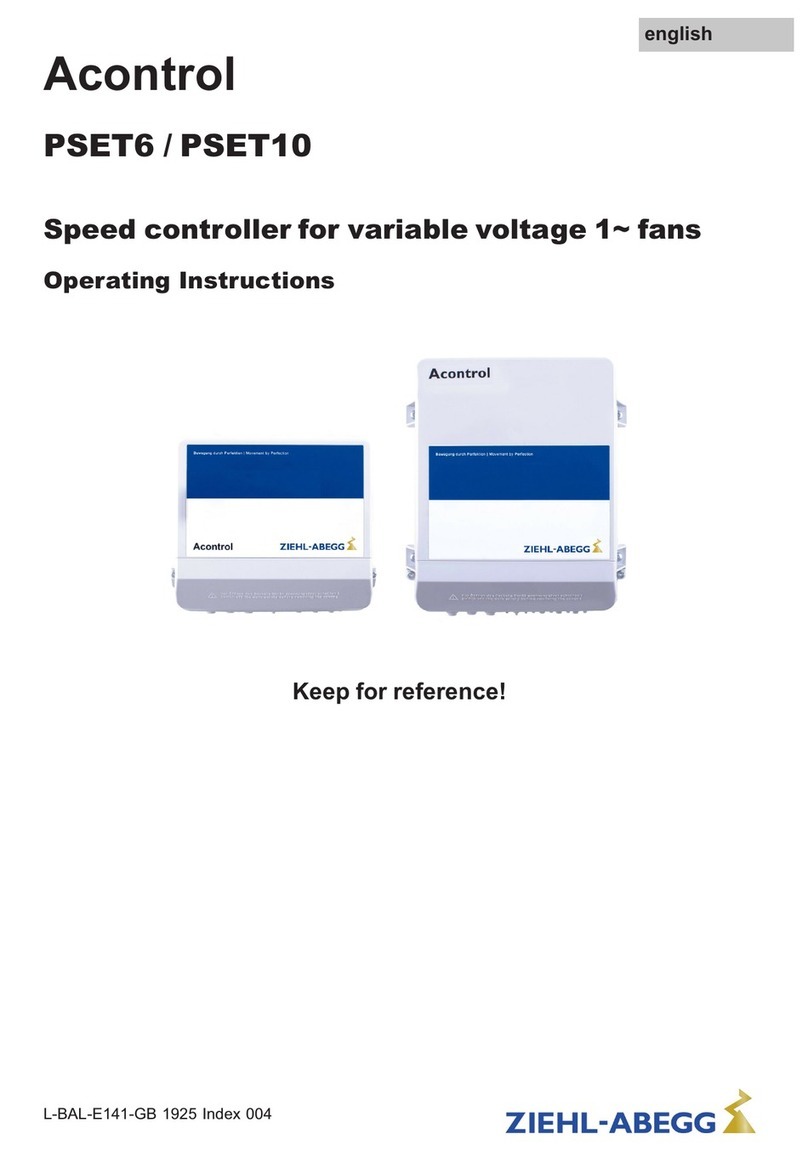
ZIEHL-ABEGG R-E-0.5E User manual

Betriebsanleitung
Typ R-E-0.5E
Transformatorisches Steuergerät für span-
nungssteuerbare 1~ otoren
Inhaltsübersicht
Kapitel Seite
Bedeutung der Betriebsanleitung ...............1
Haftungsausschluss ........................1
Sicherheitshinweise.........................1
Funktion ................................2
Lagerung ................................2
Entsorgung / Recycling ......................2
nstallation & nbetriebnahme ..................2
Störungsbeseitigung ........................3
Technische Daten ..........................3
Anschlussplan / Maßblatt [mm] .................3
Herstellerhinweis...........................4
Bedeutung der Betriebsanleitung
Lesen Sie vor Installation und Inbetriebnahme
sorgfältig diese Betriebsanleitung, um einen
korrekten Gebrauch sicherzustellen!
Wir weisen darauf hin, dass diese Betriebsan-
leitung nur gerätebezogen und keinesfalls für
die komplette Anlage gilt!
Die vorliegende Betriebsanleitung dient zum
sicherheitsgerechten Arbeiten an und mit dem
genannten Gerät. Sie enthält Sicherheitshinweise,
die beachtet werden müssen, sowie nforma-
tionen, die für einen störungsfreien Betrieb des
Gerätes notwendig sind.
Die Betriebsanleitung ist am Gerät aufzube-
wahren. Es muss gewährleistet sein, dass alle
Personen, die Tätigkeiten am Gerät auszuführen
haben, die Betriebsanleitung jederzeit einsehen
können.
Haftungsausschluss
Änderungen der Konstruktion und technischen
Daten behalten wir uns im nteresse der Weiter-
entwicklung vor. Aus den Angaben, Abbildungen
bzw. Zeichnungen und Beschreibungen können
deshalb keine Ansprüche hergeleitet werden. Der
rrtum ist vorbehalten.
Wir haften nicht für Schäden aufgrund von Fehlge-
brauch, sachwidriger Verwendung, unsachge-
mäßer Verwendung oder als Folge von nicht auto-
risierten Reparaturen bzw. Veränderungen.
Sicherheitshinweise
•Montage, elektrischer Anschluss und nbetrieb-
nahme dürfen nur von einer Elektrofachkraft,
entsprechend den elektrotechnischen Regeln
(u. a. D N EN 50110 od. D N EN 60204) vorge-
nommen werden!
•Personen, die mit Planung, nstallation, nbe-
triebnahme sowie Wartung und nstandhaltung
in Verbindung mit dem Gerät betraut sind,
müssen über die ihrer Tätigkeit entsprechenden
Operating Instructions
Type R-E-0.5E
Transformer based controller for variable
voltage 1~ motors
ontents
hapter Page
Structure of the operating instructions ............1
Exclusion of liability.........................1
Safety information ..........................1
Function ................................2
Storage .................................2
Waste disposal / recycling ....................2
Installation & Startup ........................2
rouble shooting ...........................2
echnical data ............................2
Connection diagram / Dimensions [mm]...........3
Manufacturer reference ......................3
Structure of the operating instructions
Before installation and start-up, read this
manual carefully to ensure correct use!
We emphasize that these operating instruc-
tions apply to specic units only, and are in no
way valid for the complete system!
Use these operating instructions to work safely
with and on the device. hey contain safety
instructions that must be complied with as well as
information that is required for failure-free opera-
tion of the device.
Keep these operating insturctions together with
the device. It must be ensured that all persons that
are to work on the device can refer to the oper-
ating instructions at any time.
Exclusion of liability
o allow for future developments, construction
methods and technical data given are subject to
alteration. We do not accept any liability for
possible errors or omissions in the information
contained in data, illustrations or drawings
provided.
We accept no liability for damage caused by
misuse, incorrect use, improper use or as a conse-
quence of unauthorized repairs or modications.
Safety information
•Installation, electrical connection, and start-up
operation may only be carried out by an elec-
trical specialist in accordance with electrotech-
nical regulations (e.g. DIN EN 50110 or DIN EN
60204).
•Persons entrusted with the planning, installa-
tion, commissioning and maintenance and serv-
icing in connection with the device must have
the corresponding qualications and skills for
1englishdeutsch
-L-BAL-E065-D-GB-0903- ndex 001
Qualikation und Kenntnisse verfügen. Zusätz-
lich müssen sie Kenntnisse über Sicherheitsre-
geln, EG-Richtlinien, Unfallverhütungsvor-
schriften und der entsprechenden nationalen
Vorschriften sowie regionale und innerbetrieb-
liche Vorschriften besitzen.
•Das Gerät ist ausschließlich für die in der
Auftragsbestätigung genannten Aufgaben
bestimmt. Eine andere oder darüber hinausge-
hende Benutzung, wenn nicht vertraglich
vereinbart, gilt als nicht bestimmungsgemäß.
Für hieraus resultierende Schäden haftet der
Hersteller nicht. Das Risiko trägt allein das
Verwenderunternehmen.
•Es ist grundsätzlich verboten, Arbeiten an unter
Spannung stehenden Teilen durchzuführen.
Schutzart des geöffneten Gerätes ist P00!
Gefährliche Spannungen können direkt berührt
werden!
•Während des Betriebes muss das Gerät
geschlossen sein.
•Der Betreiber ist verpichtet, das Gerät nur in
einwandfreiem Zustand zu betreiben.
•Elektrische Ausrüstungen sind regelmäßig zu
überprüfen: Lose Verbindungen sind wieder zu
befestigen, beschädigte Leitungen oder Kabel
sofort auszutauschen.
•Elektrische Einrichtungen niemals mit Wasser
oder anderen Flüssigkeiten reinigen.
•Sicherungen dürfen nur ersetzt und nicht repa-
riert oder überbrückt werden.
•Die Spannungsfreiheit ist mit einem zweipoligen
Spannungsprüfer festzustellen.
•Bei einer Störung oder bei Ausfall des Gerätes
ist zur Vermeidung von Personen- oder Sach-
schäden eine separate Funktionsüberwachung
mit Alarmierungsfunktionen erforderlich, Ersatz-
betrieb muss berücksichtigt werden!
Funktion
Prozess gesteuerter transformatorischer Dreh-
zahlsteller für spannungssteuerbare 1~ Ventila-
toren.
Die Einstellung der 5-Stufen erfolgt manuell über
die beiden Drucktaster.
|
▼
|
0-1-2-3-4-5
|
▲
|
Die Höhe der Stufe wird über LEDs angezeigt.
Nach Netzausfall ist eine manuelle Wiederein-
schaltung erforderlich.
Lagerung
•Das Gerät muss trocken und wettergeschützt in
Originalverpackung gelagert werden.
•Vermeiden Sie extreme Hitze- oder Kälteeinwir-
kung.
•Vermeiden Sie zu lange Lagerzeiten (wir
empfehlen max. ein Jahr).
Entsorgung / Recycling
Die Entsorgung muss sachgerecht und umwelt-
schonend, nach den gesetzlichen Bestimmungen
erfolgen.
these jobs. In addition, they must be knowl-
edgeable about the safety regulations, EU
directives, rules for the prevention of accidents
and the corresponding national as well as
regional and in-house regulations.
•he equipment is to be used solely for the
purposes specied and conrmed in the order.
Other uses which do not coincide with, or which
exceed those specied will be deemed unau-
thorised unless contractually agreed. Damages
resulting from such unauthorised uses will not
be the liability of the manufacturer. he user will
assume sole liability.
•It is strictly forbidden for work to be carried out
on any components while they are connected to
live voltage. he open equipment is protected to
IP00. It is possible to come into direct contact
with dangerous voltages!
•he device must be closed during operation.
•he owner is obliged to ensure that the device
are operated in perfect working order only.
•Inspect electrical equipment periodically:
retighten loose connections –immediately
replace damaged lines and cables.
•Never clean electrical equipment with water or
similar liquids.
•Fuses must be replaced and not repaired or
bridged.
•he safe isolation from the supply must be
checked using a two-pole voltage detector.
•A separate fault and performance monitoring-
system with an alarm signal function is neces-
sary in order to prevent personal injuries and
material damages during malfunctions and in
case the device fails. Substitute operation must
be taken into consideration!
Function
Process-controlled transformer based controller
for voltage controllable 1~ fans.
Setting of the 5 steps manually by the two push-
buttons. .
|
▼
|
0-1-2-3-4-5
|
▲
|
he height of the step is indicated over LEDs.
After power failure a manual restarting is neces-
sary.
Storage
•he device must be stored in its original pack-
aging in a dry and weather-proof room.
•Avoid exposure to extreme heat and cold.
•Avoid over-long storage periods (we recom-
mend a maximum of one year).
Waste disposal / recycling
Disposal must be carried out professionally and
environmentally friendly in accordance with the
legal stipulations.
2englishdeutsch
-L-BAL-E065-D-GB-0903- ndex 001
Installation & Inbetriebnahme
•Vor der Montage Gerät aus Verpackung
nehmen und auf eventuelle Transportschäden
überprüfen!
•Eine ontage ist nur im mitgelieferten Unter-
putzgeäuse zulässig. Um eine ausreichende
Abfuhr der Verlustleistung zu ermöglichen,
muss das Gehäuse durch Eingipsen mit
dem Untergrund verbunden werden
( ontage für Unterputzschalter gemäßEN
60669-2-1). Die Verwendung von ontage-
schaum und der Einsatz von Hohlwand-
dosen, statt der beiliegenden Unterputz-
dose, ist wegen der reduzierten Wärmeleit-
fähigkeit nicht zulässig!
•Netz- und Motorkabel fachgerecht einführen
und Anschluss gemäßSchaltbild vornehmen.
Danach den Drehzahlsteller mit beiliegenden
Schrauben im Unterputzgehäuse montieren.
Anschließend Frontplatte anbringen und
ordnungsgemäße Funktion prüfen.
•Eine Montage auf vibrierendem Untergrund ist
nicht zulässig.
•Schützen Sie das Gerät vor direkter Sonnenbe-
strahlung und achten Sie auf ordnungsgemäße
Wärmeabfuhr! Reinigung nur mit nicht aggres-
siven Mitteln.
•Es dürfen nur spannungssteuerbare Motoren
angeschlossen werden. Jeder otor muss
thermisch gesichert sein. Es können mehrere
Motoren angeschlossen werden. Dabei darf die
Summe der max. Regelströme aller Motoren
den Bemessungsstrom des Drehzahlstellers
nicht überschreiten.
•Der eingebaute Spartransformator ist nicht kurz-
schlussfest, die Größe der internen Sicherung
und die maximale Vorsicherung ist unbedingt zu
beachten ( FTechnische Daten)!
•Nach Versorgung mit Netzspannung ist eine
Wartezeit von ca. 40 sec. erforderlich, bevor
das Gerät über der “AUF”Taste in Betrieb
genommem werden kann.
Störungsbeseitigung
Netzspannung, Anschlussklemmen und interne
Gerätesicherung überprüfen.
Nach Versorgung mit Netzspannung Wartezeit
von ca. 40 sec. beachten!
Nach Netzausfall ist eine manuelle Wiederein-
schaltung erforderlich.
Technische Daten
Typ: R-E-0.5E
Art.-Nr.: 302099
Netzspannung:
1 ~ 230 V (-10 % / +10 %), 50/60 Hz
Ausgangsspannungen (5 - Stufen):
80 V - 110 V - 170 V- 200 V - 230 V
Bemessungsstrom: 0,5 A
Installation & Startup
•Before installation remove the device from the
packing and check for any possible shipping
damage!
•Installation is only possible in the enclosed
ushmounted housing. In order to enable
adequate power loss dissipation, the
housing must be connected to the base by
plastering (installation for ush-mounted
switches according to EN 60669-2-1). The
use of installation foam and insertion of
hollow wall outlets in place of the ush-
mounted outlet is not permitted due to the
reduced heat conductivity!
•Insert the power cable and motor cable properly
and connect according to the circuit diagram.
hen install the speed governor in the ush-
mounted housing with the enclosed screws.
Finally t the face plate and test for proper func-
tion.
•Do not mount equipment on vibrating base.
•Protect the device from direct exposure to
sunlight. Be sure to observe proper heat dissi-
pation. Cleaning only with not aggressive
means.
•Only voltage controllable motors may be
connected. Each motor must be protected
against overheating. Several motors can be
connected to the controller. he maximum total
current of all motors must not exceed the rated
current of the controller.
•he internal autotransformer is not short-circuit-
proof, note maximum size of line fuse absolutely
(Fechnical data)!
•After applying mains voltage, you have to wait
for about 40 seconds before the device can be
started by the “UP”button.
Trouble shooting
Check line, connection and internal device fuse.
Wait about forty seconds after applying mains
voltage!
After power failure a manual restarting is neces-
sary.
Technical data
Type: R-E-0.5E
Part.-No.: 302099
Line voltage:
1 ~ 230 V (-10 % / +10 %), 50/60 Hz
Output voltage (5 - steps):
80 V - 110 V - 170 V- 200 V - 230 V
Rated current: 0.5 A
Max. heat dissipation: approx. 15 W
3englishdeutsch
-L-BAL-E065-D-GB-0903- ndex 001
Max. Verlustleistung: ca. 15 W
Verlustleistung im Standby Betrieb (Gerät am
Netz keine Stufe ausgewählt): ca. 0,05 W
nterne Sicherung: T 500 mA (5 x 20 mm)
Max. Vorsicherung: 16 A
Max. zulässige Umgebungstemperatur: 35 °C
Störaussendung gemäßEN 61000-6-3
Störfestigkeit gemäßEN 61000-6-2
Einbau in 2er Kombi - UP Dose (im Lieferum-
fang)
Frontplatte aus Durolon (UV Licht beständig)
Schutzartz in eingebautem Zustand: P 30
Gewicht: 0,77 kg
Anschlussplan / aßblatt [mm]
1. Netz 1 ~ 230 V, 50/60 Hz
2. 1 ~ Motor ohne Thermostatschalter
3. nterne Sicherung
5((
SR177K01
06.02.2009
NP
NL1PE
P1N
M
1~
PE U2 U1
230 V
M
1~
Netz
Line
1 ~ 230 V 50/60 Hz
1
1 ~ Motor
ohne Thermostatschalter
without thermostats
2
3
Herstellerhinweis
Unsere Produkte sind nach den einschlägigen
internationalen Vorschriften gefertigt. Haben Sie
Fragen zur Verwendung unserer Produkte oder
planen Sie spezielle Anwendungen, wenden Sie
sich bitte an:
Ziehl-Abegg AG
Heinz-Ziehl-Straße
74653 Künzelsau
Telefon: +49 (0) 7940 16-0
Telefax: +49 (0) 7940 16-504
info@ziehl-abegg.de
http://www.ziehl-abegg.de
Heat dissipation in standby operation (device at
line no step selected): approx. 0.05 W
Internal fuse: 500 mA (5 x 20 mm)
Max. line fuse: 16 A
Max. permissible ambient temperature: 35 °C
Interference emission according to EN 61000-
6-3
Interference immunity according to EN 61000-
6-2
Mounting in double in-wall box (included in
scope of delivery)
Front panel made of Durolon (UV light resistant)
Protection class when mounted: IP 30
Weight: 0.77 kg
onnection diagram / Dimensions [mm]
1. Line 1 ~ 230 V, 50/60 Hz
2. 1 ~ Motor without thermostats
3. Internal fuse
Manufacturer reference
Our products are manufactured in accordance
with the relevant international regulations. If you
have any questions concerning the use of our
products or plan special uses, please contact:
Ziehl-Abegg AG
Heinz-Ziehl-Straße
74653 Künzelsau
Telephone: +49 (0) 7940 16-0
Telefax: +49 (0) 7940 16-504
info@ziehl-abegg.de
http://www.ziehl-abegg.de
4englishdeutsch
-L-BAL-E065-D-GB-0903- ndex 001
Other ZIEHL-ABEGG Controllers manuals

ZIEHL-ABEGG
ZIEHL-ABEGG R-E-1.5G User manual

ZIEHL-ABEGG
ZIEHL-ABEGG R-DK Series User manual

ZIEHL-ABEGG
ZIEHL-ABEGG Dcontrol PKDM6 User manual

ZIEHL-ABEGG
ZIEHL-ABEGG PAE10E-M User manual

ZIEHL-ABEGG
ZIEHL-ABEGG RAE-2G User manual

ZIEHL-ABEGG
ZIEHL-ABEGG Acontrol PDE-6 User manual

ZIEHL-ABEGG
ZIEHL-ABEGG DControl PKDT Series User manual

ZIEHL-ABEGG
ZIEHL-ABEGG Acontrol PSET6 User manual

ZIEHL-ABEGG
ZIEHL-ABEGG Acontrol PKE-6 User manual

ZIEHL-ABEGG
ZIEHL-ABEGG Acontrol PXET6Q User manual