Installation & Operating Instructions - 801957UK_DOMCTS - Zip ChillTap Sparkling - June 2014 V 2.01 Page 7 of 14
Step D - Connecting:
NOTE: You must separately supply and install an isolation valve (not supplied)
in the supply line before the connection to the product.
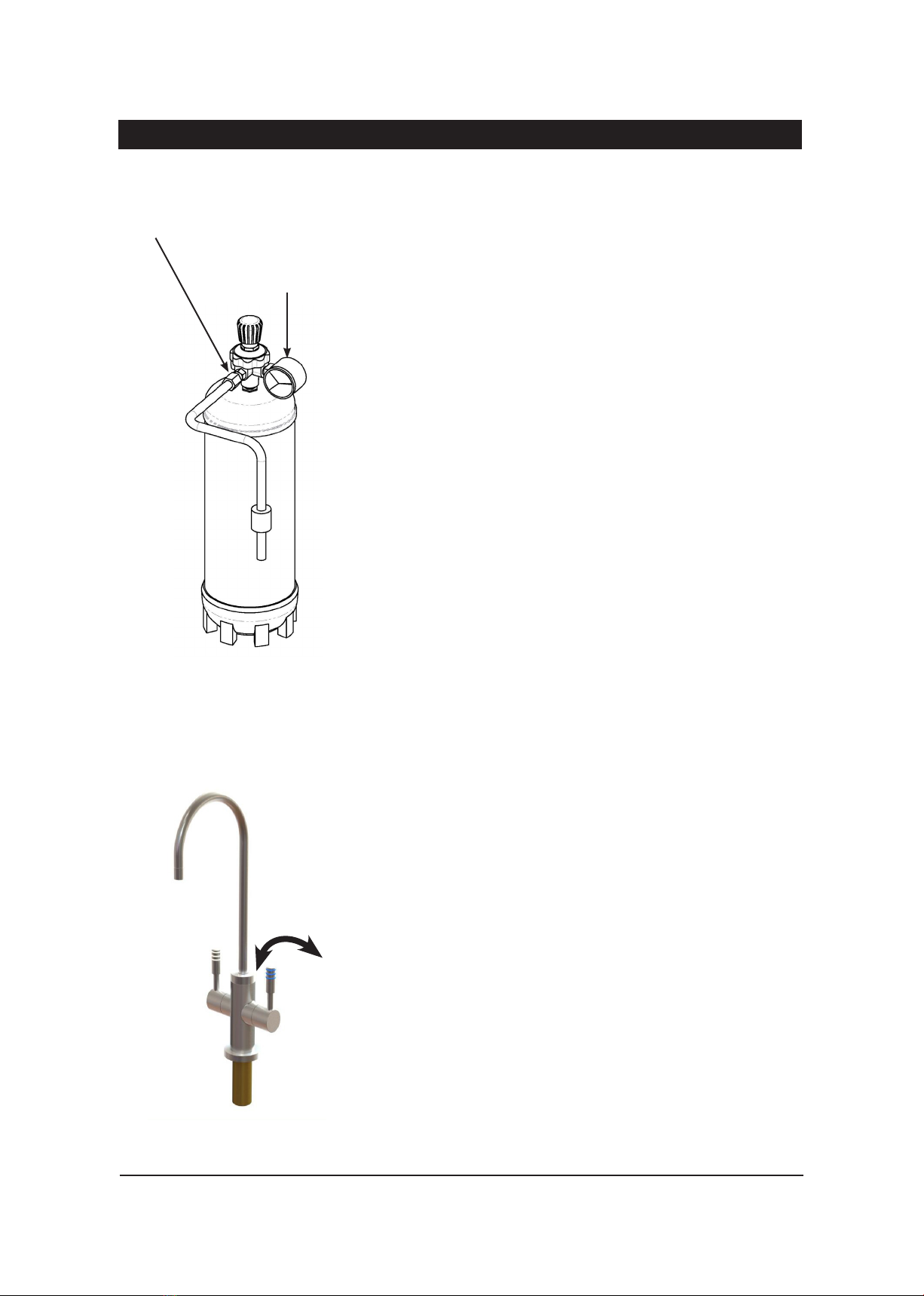
If required connect the 0.35 MPa (3.5 bar) pressure limiting valve (supplied) to
the isolation valve. Minimum supply pressure must be 0.14 MPa (1.4 bar).
For best results we recommend a minimum static pressure of 0.2 MPa (2 bar).
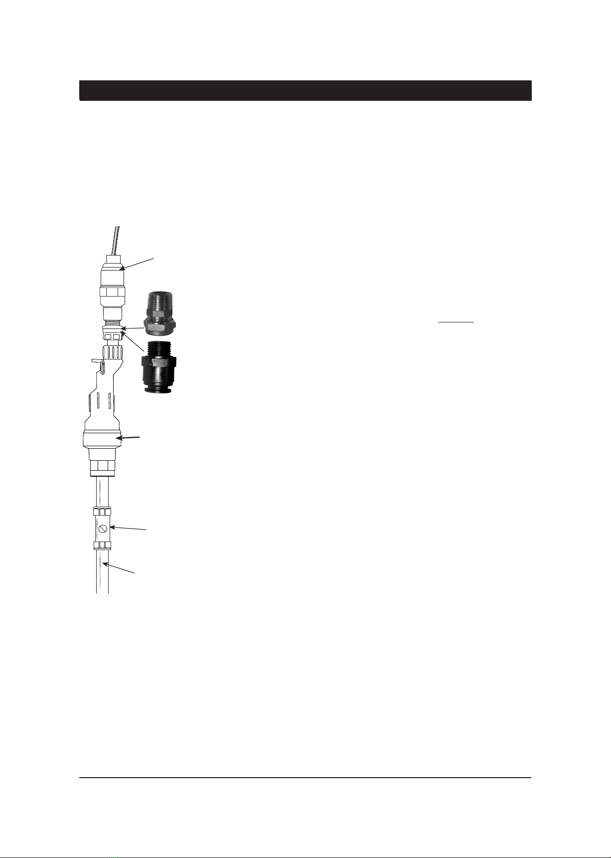
Caution! Installing the pressure limiting valve to mains water supply (Fig. a):
The pressure limiting valve may be supplied with one of two 15mm mains
fittings:
1. *A brass ½” BSP male taper x 15mm compression connection.
If fitting the brass compression fitting, ensure that you use sufficient PTFE
tape on the taper thread.
2. **A plastic JG fitting (15mm to ½”BSP)
Do not use PTFE tape on the plastic screw thread of the JG fitting, take care
not to overtighten the fitting, hand tight plus ¼ turn maximum. The use of
PTFE tape or over-tightening of plastic fittings may result in leaks.
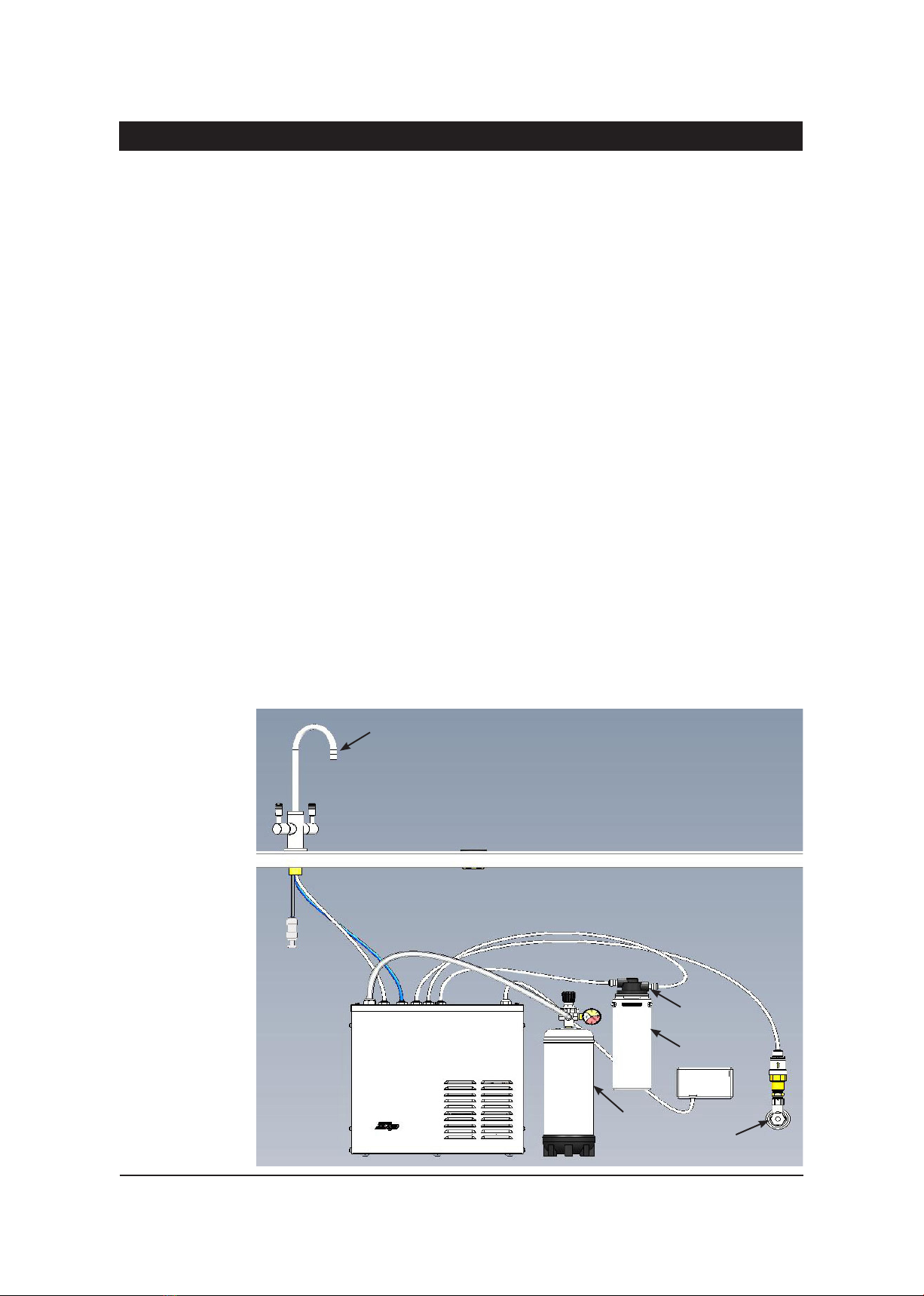
Mains Connection (with chiller inlet):
Take the supplied ¼” white John Guest tubing, measure, cut and connect the
tube from the outlet of the pressure limiting valve to the “Mains Inlet“ on the
top of the unit.
Make sure all connections to John Guest fittings are pushed in past the
“O”ring to full depth, at least 15-16mm.
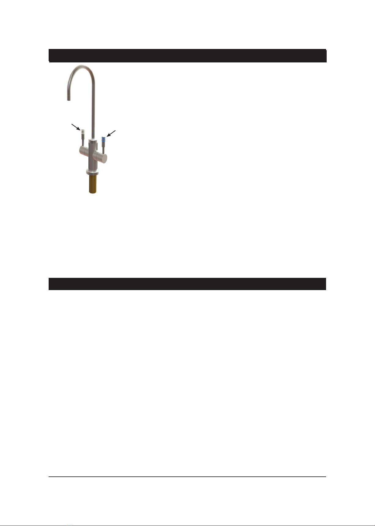
Chilled Still Connection:
Remove the plug fitted into the connection marked “Still Outlet“ by first
depressing the collet and simultaneously pulling out the plug. Measure and
trim the ¼” blue tube from the carafe tap to the JG fitting marked “Still Outlet”
on the top rear of the chiller unit. Before making connection, insulate the tube
with the loose length of the pipe insulation, trim the insulation pipe to correct
length, which is about 10mm shorter than blue tube. Push the blue tube fully
into the John Guest fitting marked “Still Outlet”. Make sure all connections to
John Guest fittings are pushed in past the “O”ring to full depth.
Chilled Sparkling Connection:
Remove the plug fitted into the connection marked “Sparkling Outlet“ by
first depressing the collet and simultaneously pulling out the plug. Similarly,
measure and trim the ¼” white tube from the carafe tap to the JG fitting
marked “Sparkling Outlet” on the top rear of the chiller unit. Before making
connection, insulate the tube with the loose length of the pipe insulation,
trim the insulation pipe to correct length, which is about 10mm shorter than
white tube. Push the white tube filling into the in John Guest fitting marked
“Sparkling Outlet”. Make sure all connections to JG fittings are pushed in past
the “O”ring to full depth.
Using the tubing clamps to tidy up the installation.
The tap connection is now complete.
Installation Instructions continued
NOTE: Take care, when bending
rigid plastic tubing, to prevent it
from kinking or crushing around
a bend. As it is plastic tubing
containing water under mains
pressure, be careful not to nick,
scratch or damage it during
installation.
Pressure limiting Valve
(Supplied)
Isolation Valve
Not Supplied
Mains Water Supply
Fig.a
*
**
Recommended
Optional Water Block