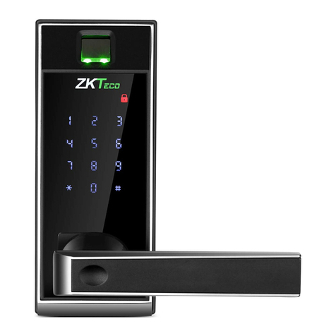
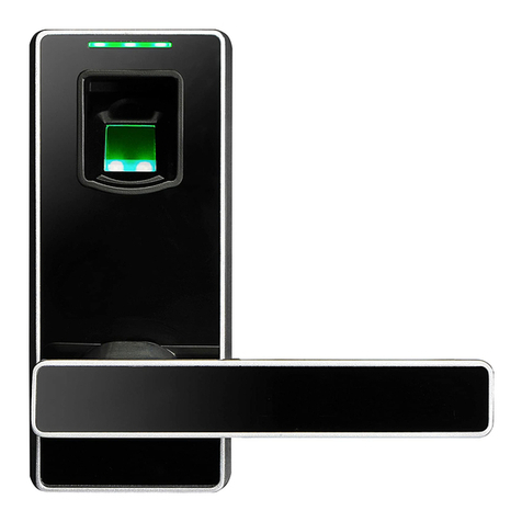
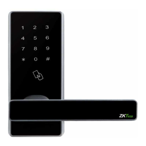
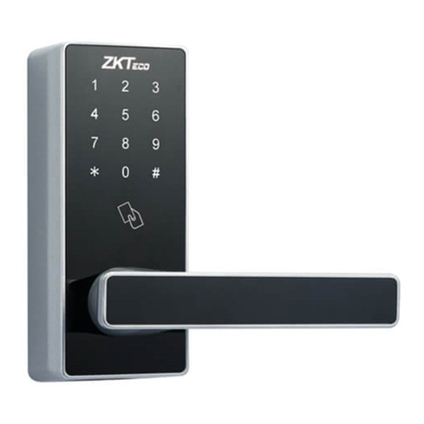
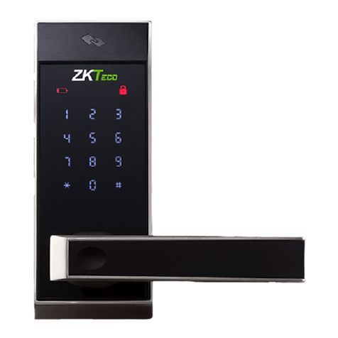
ZKTeco ML200 Series User manual

Installation Guide
Model: ML200/ML300 Series
Lock Body: American Standard Single Latch
Version: 1.0
English

What's in the Box.............................................................................................................1
Installation Diagram.......................................................................................................2
Installation Procedure....................................................................................................2
1. Door Properties..........................................................................................................................................2
2. *Drilling Holes on the Door....................................................................................................................3
3. Installing Latch...........................................................................................................................................4
4. Installing Outdoor Unit...........................................................................................................................5
5. Installing Mounting Plate and Gasket......................................................................................6
6. Installing Indoor Unit...................................................................................................................6
7. Installing Batteries and Cover...............................................................................................................7
8. Installing Strike Plate and Box......................................................................................................8
9. Physical Testing..........................................................................................................................................8
Important Notes
Please read this Installation Guide carefully or contact the Customer Care for any
queries regarding installation.
Installation is recommended to be performed by a professional to avoid any
additional service charges that may cause due to improper product installation.
We constantly revise the contents of this Installation Guide and update our products
to improve the quality and performance without any prior notice.
Do not insert batteries before installing the lock.
1.
2.
3.
4.
Table of Contents

1
What's in the Box
Outdoor Unit Indoor Unit Gasket Mounting Plate
Latch
Spindle
Strike Plate
and Box
Keys Hex Wrench
Screw A Screw B Screw C Screw D
Door Thickness
30 to 37 mm
38 to 45 mm
46 to 53 mm
Spindle
56 mm
64 mm
72 mm
Screw B
20 mm
30 mm
35 mm
Screw C
25 mm
35 mm
40 mm
Note: Screws and Spindles for the doors of thickness from 30 to 60 mm are included in the
standard package. Please use the appropriate set of Screws and Spindles as per your
door's thickness, to assure the proper functioning of the lock.
Stud Double Sided
Tapes
Screw E
54 to 60 mm 80 mm 45 mm 50 mm

Installation Diagram
2
Installation Procedure
1Door Properties
Measure the door thickness
A.
Measure the door thickness and select the proper Spindle and Screw length. For details,
please refer to the table contents of Page 1.
Check the door opening direction
B.
The position of the handle is determined by the opening direction of the door. Below is
the graphical representation of door opening direction in reference to your location
outside the room.
Battery Cover
Battery
(not included)
Indoor
Unit
Door
Key
Mounting
Plate
Gasket Gasket
Outdoor Unit
Strike Plate
and Box
Latch
Screw A
Screw D
Screw C / Screw E
(optional)
Stud (optional)
Double Sided Tape
(optional)
Optional
Important Notice
You can either use the provided Double Sided Tapes or Stud to stabilize the
Outdoor Unit. Stud requires drilling an extra hole.
*
Spindle
Screw B

3
User Location
LatchStrikePlateLatch
LatchStrikePlateLatch StrikePlate
StrikePlate
Left Inward Right Inward
Left Outward Right Outward
Change the handle direction (if needed)
C.
Use the Hex Wrench to remove the Screw of the handle. Take the handle out from the
lock.
Change the handle direction and place it again and fix it by using the Screw.
1)
2)
2*Drilling Holes on the Door
Place the Installation Template at the desired handle height.
Mark for the holes to be drilled and drill the marked places.
1)
2)

4
Center line of the handle
Desired handle height
60/70mm
Door thickness
30~60mm
Backset
*
NOTE
1)
2)
* If you don’t want to drill an extra hole on your door, you can just skip this
step.
If you wish to have added stability, drill for the hole by referring to the
provided Installation Template.
3Installing Latch
Adjust the backset of the lock. (if needed)
Fix the Latch with the Screw A. Make sure the Latch angle faces the door jamb.
1)
2)
Screws A
2-3/4
2-3/4
2-3/8
70mm
60mm
70mm
2-3/42-3/8
60mm
*

5
4Installing Outdoor Unit
There are two methods to install the Outdoor Unit.
vMethod 1: Installing with Double Sided Tapes
Paste a Double Sided Tape on the Mounting Plate of the Outdoor Unit.
Insert the Spindle into the clutch. Make sure the triangle mark points to the
vertically centred position.
Attach the Outdoor Unit to the door by inserting the cable through the drilled holes.
1)
2)
3)
Clutch c orrect p osition:
T he triangle must be vertically centered.
vMethod 2: Installing with Stud
Fix the Stud on the Mounting Plate of the Outdoor Unit.
Insert the Spindle into the clutch. Make sure the triangle mark points to the
vertically centred position.
Attach the Outdoor Unit to the door by inserting the cable through the drilled holes.
1)
2)
3)
Clutch c orrect p osition:
T he triangle must be vertically centered.
*

5Installing Mounting Plate and Gasket
6
Attach the Mounting Plate to the Gasket and route the cable through the hole.
Place the Gasket and Mounting Plate on to the door and use Screw B to fix them.
1)
2)
Screw B
Select the Indoor Unit Installation method according to the previously selected
Outdoor Unit Installation method in Step 4.
6Installing Indoor Unit
Connect the cables to the port on the Indoor Unit.
Place the Indoor Unit properly on the Mounting Plate. Then use Screw D & Screw E to
fix the Indoor Unit.
1)
2)
vMethod 1: Installing with Double Sided Tapes
Note: Fix the Screw E into the wooden door with the Screwdriver.
Screw
D E
*

7
Connect the cable to the port on the Indoor Unit.
Place the Indoor Unit properly on the Mounting Plate. Then use Screw C & Screw D to
fix the Indoor Unit.
1)
2)
vMethod 2: Installing with Stud
Insert four Alkaline AA batteries and cover them with a battery cover.
7Installing Batteries and Cover
Screw
D C

8
Make sure that the Strike Box is aligned with the Latch bolt. Then, use the Installation
Template to drill holes.
Align the Strike Plate and Box with the drilled holes and fix them with Screw A.
8Installing Strike Plate and Box
1)
2)
58mm
(5/64")
35mm
14mm
29mm
21mm
12mm
2mm
(53/64")
(35/64")
(1-3/8")
(1-9/64")
(2-9/32")
(15/32")
Screws A
depth
depth
9Physical Testing
Test the lock by rotating the handle.
A.
Note: When the door is locked, the front handle can be turned, but the door will remain
locked.
B. Test the lock by using the mechanical key.
Insert the Key into key hole and rotate 90°, then rotate down the handle to open the door.

Guía de Instalación
Modelo: Series ML200/ML300
Estándar de la Cerradura: Estándar Americano
Versión: .1 0
Español

Contenido de la Caja.......................................................................................................1
Diagrama de Instalación................................................................................................2
Pasos de Instalación.......................................................................................................2
1. Propiedades de las Puertas.....................................................................................................................2
2. Taladrar agujeros en la puerta .............................................................................................................3
3. Instalar el pestillo.......................................................................................................................................4
4. Instalación de la unidad exterior..........................................................................................................5
5. Instalación de la placa de montaje y junta........................................................................................6
6. Instalación de la unidad interior...........................................................................................................6
7. Instalación de la batería y la cubierta..................................................................................................7
8. Instalación de la placa metálica y la contra chapa..........................................................................8
9. Prueba física................................................................................................................................................8
Notas Importantes
Lea atentamente esta guía de instalación o póngase en contacto con el servicio de
atención al cliente si tiene alguna pregunta relacionada con la instalación.
Se recomienda que la instalación la realice un profesional para evitar cualquier cargo
de servicio adicional que pueda causar debido a una instalación incorrecta del
producto.
Revisamos constantemente el contenido de esta guía de instalación y actualizamos
nuestros productos para mejorar la calidad y el rendimiento sin previo aviso.
No inserte las pilas antes de instalar la cerradura.
1.
2.
3.
4.
Tabla de Contenido

1
30 a 37 mm
38 a 45 mm
46 a 53 mm
56 mm
64 mm
72 mm
20 mm
30 mm
35 mm
25 mm
35 mm
40 mm
Nota: Los tornillos y pernos para las puertas de espesor de 30 a 60 mm están incluidos en
el paquete estándar. Utilice el juego de tornillos adecuado según el grosor de su puerta,
para asegurar el correcto funcionamiento de la cerradura.
54 to 60 mm 80 mm 45 mm 50 mm
Contenido de la Caja
Unidad Exterior Unidad Interior Junta Placa de Montaje
Pestillo Placa Metálica y
Contrachapa
Taquete Cinta Doblecara Llaves Llave
Hexagonal
Perno Tornillo A Tornillo B Tornillo C Tornillo D Tornillo E
Grosor de la puerta Tornillo B Tornillo C
Perno

2
Opcional
Nota Importante
Puede utilizar las cintas o taquete suministrados para estabilizar la unidad
exterior. El taquete requiere perforar un orificio adicional.
*
Diagrama de Instalación
Tornillos C / Tornillos E
(Opcional)
Baterías
(no incluidas)
Covertura para
las baterías
Unidad
Interior
Tornillo D
Tornillo B
Llaves
Unidad Exterior
Taquete (Opcional)
Puerta
Junta Junta
Perno
Pestillo
Tornillo B
Placa Metálica y
Contrachapa
Cinta Doblecara
Placa de
Montaje
Pasos de Instalación
1Propiedades de las Puertas
Medidas y grosor de la puerta
A.
Mida el grosor de la puerta y seleccione el perno y la longitud de tornillo adecuados. Para
más detalles, consulte el contenido de la tabla de la página 1.
Verifique la dirección de apertura de la puerta
B.
La posicion de manija es determinada po la dirección de apertura de la puerta. Debajo se
encuentra la representación gráfica de la apertura de la puerta, referencia a su ubicación
fuera de la habitación.

Punto de Vista
Pestillo Placa Metálica
Izquierda hacia adentro Derecha hacia adentro
Izquierda hacia afuera Derecha hacia afuera
Placa Metálica
Pestillo Placa Metálica Placa Metálica Pestillo
Pestillo
3
2*Taladrar agujeros en la puerta
Coloque la plantilla de instalación a la altura deseada de la manija.
Marcar los agujeros y perforar los lugares marcados.
1)
2)
C.
1)
2)
Cambie la dirección de la manija (si es necesario)
C.
Use una Llave Hexagonal para quitar el tornillo de la manija. Retire la manija de la
cerradura.
Cambie la dirección y vuelva a colocar la manija en su posición. De nuevo asegure la
manija con el tornillo.
1)
2)

4
Línea central de la manija
Altura deseada de la manija
60/70mm
Grosor de la puerta
30~60mm
Fondo
*
NOTA
1)
2)
* Si no desea perforar este orificio adicional en su puerta, puede omitir
este paso.
Si desea tener mayor estabilidad, perfore el orificio consultando la
plantilla de instalación proporcionada.
3Instalar el pestillo
Ajuste el fondo de la cerradura. (si es necesario)
Asegure el pestillo con el tornillo A.
1)
2)
Tornillo A
2-3/4
2-3/4
2-3/8
70mm
60mm
70mm
2-3/42-3/8
60mm
*

5
4Instalación de la unidad exterior
Hay dos métodos para instalar la unidad exterior.
vMétodo 1: Instalación con cinta doblecara
Pegue una cinta en la placa de montaje de la unidad exterior.
Inserte el perno en el embrague. Asegúrese de que la marca del triángulo apunte a la
posición centrada verticalmente.
Conecte la unidad exterior a la puerta insertando el cable a través de los orificios
perforados.
1)
2)
3)
Posición correcta del embrague:
El triángulo debe estar centrado verticalmente.
vMétodo 2: Instalación con taquete
Fije el taquete en la placa de montaje de la unidad exterior.
Inserte el eje en el embrague. Asegúrese de que la marca del triángulo apunte a la
posición centrada verticalmente.
Conecte la unidad exterior a la puerta insertando el cable a través de los orificios
perforados.
1)
2)
3)
Posición correcta del embrague:
El triángulo debe estar centrado verticalmente.
*

5Instalación de la placa de montaje y junta
6
Fije la placa de montaje a la junta y pase el cable a través del orificio.
Coloque la junta y la placa de montaje en la puerta y use el tornillo B para asegurarlos.
1)
2)
Tornillo B
Seleccione el método de instalación de la unidad interior de acuerdo con el método de
instalación de la unidad exterior seleccionado anteriormente en el paso 4.
6Instalación de la unidad interior
Conecte los cables al puerto de la unidad interior.
Coloque la unidad interior correctamente en la placa de montaje. Luego use el
tornillo D y el tornillo E para fijar la unidad interior.
1)
2)
vMétodo 1: Instalación con cinta doblecara
Nota: Fije el tornillo E en la puerta de madera con el destornillador.
Tornillo
D E
*

7
Conecte el cable al puerto de la unidad interior.
Coloque la unidad interior correctamente en la placa de montaje. Luego use el
tornillo C y el tornillo D para fijar la unidad interior.
1)
2)
vMétodo 2: Instalación con Taquete
Inserte cuatro pilas alcalinas AA y cúbralas con la tapa de la batería.
7Instalación de la batería y la cubierta
Tornillo
D C

8
Asegúrese de que la caja esté en el mismo nivel que el pestillo del cerrojo. Utilice la
plantilla de instalación para perforar orificios.
Alinee la placa metálica y la contrachapa con los agujeros perforados y asegúrelos
con el tornillo A.
8Instalación de la placa metálica y la contrachapa
1)
2)
58mm
(5/64")
35mm
14mm
29mm
21mm
12mm
2mm
(53/64")
(35/64")
(1-3/8")
(1-9/64")
(2-9/32")
(15/32")
Tornillo A
depth
depth
9Prueba física
Pruebe la cerradura girando la manija
A.
Nota: Cuando la puerta está cerrada, la manija delantera puede girar, pero la puerta
permanece bloqueada.
B. Pruebe la cerradura usando la llave mecánica
Inserte la llave en el orificio de la llave y gire 90°, luego gire la manija hacia abajo para abrir
la puerta.
Other manuals for ML200 Series
1
This manual suits for next models
1
Table of contents
Languages:
Other ZKTeco Lock manuals

ZKTeco
ZKTeco AL30B User manual

ZKTeco
ZKTeco L 6800 User manual

ZKTeco
ZKTeco LH3000 User manual

ZKTeco
ZKTeco DL30B User manual

ZKTeco
ZKTeco DL30Z User manual

ZKTeco
ZKTeco AL20B User manual

ZKTeco
ZKTeco CL10 User manual

ZKTeco
ZKTeco PL10 Series User manual

ZKTeco
ZKTeco AL30B User manual

ZKTeco
ZKTeco DL30B User manual

ZKTeco
ZKTeco DL30DB User manual

ZKTeco
ZKTeco TL400B User manual

ZKTeco
ZKTeco ZM100 User manual

ZKTeco
ZKTeco Plock 2 User manual

ZKTeco
ZKTeco TL800 User manual

ZKTeco
ZKTeco TL300 User manual

ZKTeco
ZKTeco DL30B User manual

ZKTeco
ZKTeco AL10B User manual

ZKTeco
ZKTeco ZM100 User manual

ZKTeco
ZKTeco Padlock User manual