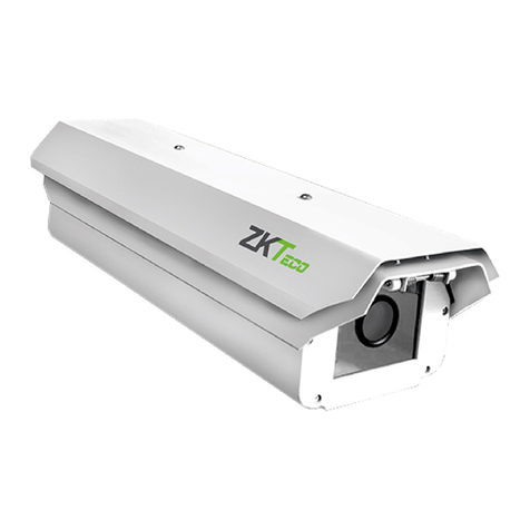
ZKTeco LPRC200-4G User manual

USER MANUAL
LPRC200-4G
Version: 1.2
Date: July 2019

Thank you for choosing our product. Before using this product, please read this user manual
carefully for smoother user experience.The information in this instruction manual is, to the
best of our knowledge, valid at the time of publication.
Unless authorized by our company, no group or individual shall take excerpts of or copy all or
part of these instructions nor transmit the contents of these instructions by any means.
The products described in this manual may include software that is copyrighted by our
company and its possible licensors. No one may copy, publish, edit, take quotes of, decompile,
decode, reverse-engineer, rent, transfer, sublicense, or otherwise intrude upon the software's
copyright unless authorized by the copyright holder(s). This is subject to relevant laws
prohibiting such restrictions.
ZKTeco believes in development, and this product will be regularly updated, in that case we
cannot guarantee exact consistency between the a
ctual product and the written
information in this manual. Our company claims no responsibility for any disputes that arise
due to differences between the actual technical parameters and the descriptions in this
document. The manual is subject to change without prior notice.

ZKTeco owns all parts of this product including its accessories and software and reserves the right of
final version. The information provided in this manual is in association with ZKTeco products. The
performance data and software functions described in this user manual are for your reference only.
ZKTeco reserves the right to revise the description of the product at any time without notice to
improve functions.
ZKTeco will not accept any legal responsibilities arising from the illegal use of this product.

Since 1998, the founders of ZKTECO CO., LTD (ZKTeco) have been determined for independent
research and development of biometric verification procedures and the productization of biometric
verification SDK, which was initially widely applied in PC security and identity authentication fields.
With the continuous enhancement of the development and plenty of market applications, the team
has gradually constructed identity authentication ecosystem and smart security ecosystem, which
are based on biometric verification techniques. With years of experience of the industrialization of
biometric verifications.
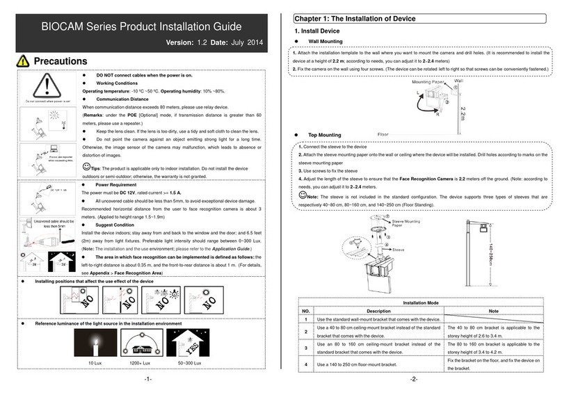
This manual introduces the operations, interfaces and functions of License Plate Recognition
Camera. For installation, please refer to the
Installation Guide
of the product accordingly.
All figures displayed are for illustration purpose only. Figures in this manual may not be exactly
consistent with the actual products.
This section describes the symbol and its purpose in the manual.
Note: This implies about the notice or pay attention to in the manual.
Tip: The general information which helps in performing the operations faster.
Important: The information which is to be considered.
Caution: Care taken to avoid danger or mistakes.
Warning: The statement or event that warns of something or that serves as a cautionary
example.

Table of Contents
Safety Precautions.............................................................................................................................................................................................1
1. Overview........................................................................................................................................................................................................2
1.1 About the Product ...........................................................................................................................................................................2
1.2 Features...................................................................................................................................................................................................2
1.3 Appearance ..........................................................................................................................................................................................3
1.4 Port Definition.....................................................................................................................................................................................3
2. Computer Connection Configuration........................................................................................................................................5
2.1 Software Environment...................................................................................................................................................................5
2.2 Network and IP Address Configuration .............................................................................................................................5
2.2.1 Default Parameter Settings.................................................................................................................................................5
2.2.2 Connectivity Test .......................................................................................................................................................................5
3. Camera Access over a Web Browser............................................................................................................................................7
3.1 Login..........................................................................................................................................................................................................7
3.2 Live...........................................................................................................................................................................................................10
3.3 File ............................................................................................................................................................................................................11
3.4 Setup......................................................................................................................................................................................................12
3.4.1 Device Information...............................................................................................................................................................12
3.4.2 Time Settings ............................................................................................................................................................................13
3.4.3 Display Settings.......................................................................................................................................................................13
3.4.4 Streams .........................................................................................................................................................................................15
3.4.5 Video Parameters.................................................................................................................................................................... 16
3.4.6 Intelligent Analysis ................................................................................................................................................................18
3.4.7 Data Management................................................................................................................................................................22
3.4.8 Push Configuration ...............................................................................................................................................................22
3.4.9 4G Configuration....................................................................................................................................................................23
3.4.10 P2P Configuration................................................................................................................................................................24
3.4.11 Network Settings..................................................................................................................................................................24
3.4.12 FTP Settings.............................................................................................................................................................................25
3.4.13 User Management ..............................................................................................................................................................26
3.4.14 Firmware Upgrade ..............................................................................................................................................................26
3.4.15 System Update ......................................................................................................................................................................27
3.4.16 Auto Reboot............................................................................................................................................................................28
3.4.17 Restore.........................................................................................................................................................................................28
3.4.18 Local Settings .........................................................................................................................................................................29
3.5 Log...........................................................................................................................................................................................................30
FAQs......................................................................................................................................................................................................................... 32

LPRC200-4G User Manual 1
Safety Precautions
Electrical safety
Before connecting an external cable to the device, complete the grounding properly and
set up surge protection; otherwise, static electricity will damage the mainboard.
Ensure that the standard voltage applicable in your country or region is used (the rated
voltage of the machine is 220V). Power mismatch may cause short circuit or device
damage.
Operation safety
The device hardware may be damaged by transportation and other unpredictable causes.
Check whether the device has serious damage before installation. If the device has major
defects, contact your dealer as soon as possible.
Do not connect or disconnect cables to/from the device when it is in working state.
Do not keep the device in a place that vibrates. Handle the device with care. Do not place
heavy objects on top of the device.
Do not apply rosin, alcohol, benzene, pesticides, and other volatile substances that can
damage the device enclosure. Clean the enclosure with a piece of soft cloth or a small
amount of cleaning agent.
Non-professional personnel are not allowed to open the device cover. If you have any
technical questions regarding usage, contact certified or experienced technical personnel.

LPRC200-4G User Manual 2
1. Overview
1.1 About the Product
LPRC stands for License Plate Recognition Camera. The LPRC200-4G is a high-performance
H.264/H.265-based license plate recognition camera and it has the properties of:
Integrating HD imaging
Image collection
License plate recognition
Image decompression
Storage of data on an embedded intelligent platform.
It automatically identifies the numbers, letters, and characters on license plates, and outputs the
identified results. At the same time, it can identify vehicle details (such as colors, auto logos and
vehicle models). It is mainly used in the field of parking charge and entry/exit management.
1.2 Features
High-performance architecture of dual-core processors, stable system architecture, powerful
computing capacity, embedded capture, analysis and recognition features.
Adopt modular structure design to ensure normal work under harsh environment.
Complete SDK can support secondary development docking, system integration is simple.
The algorithm is stable and reliable, with strong scene adaptability, and supports the
recognition of ordinary blue, black, yellow, double-layer yellow and multiple national license
plates.
Support vehicle feature recognition, including body color, logo and vehicle type.
1/2.8" wide dynamic CMOS, 2 million HD lens, high quality images, resolution up to 1920*1080.
License plate recognition accuracy reaches more than 99% in the daytime and more than 98%
at night, with a wide range of recognition angles.
4G module is optional to meet the construction requirements of field communication cabling
free.
It can support remote connection and debugging of equipment by mobile phone APP and
computer client and set parameters. It is not distance-limited and can be readily adapted
anytime and anywhere to simplify the operation, maintenance, installation and debugging of
the product.

LPRC200-4G User Manual 3
1.3 Appearance
1.4 Port Definition
Wiring terminal diagram:
Port description:
Pin Description
Reset Used to restore the original camera parameters
Ethernet
Standard Ethernet RJ45 socket, 10M/100M self-adaptive, can be con;5nected
with various network devices, such as switches, routers, hubs, etc.
USB USB connection
GND
+12V
Used to connect the power adapter. The camera's power supply voltage is
12V/3A DC. Do not use other power sources to prevent damage to the camera.
NC1
COM1
NO1
Used for connecting barrier gate
License plate recognition camera

LPRC200-4G User Manual 4
NC2
COM2
NO2
Indicator light connection (Red and Green)
485A1
485B1
RS485 transmission function used to connect the display screen and voice
module of parking system
CLOSE
GND
OPEN
Barrier switch status
Audio Used to connect audio and microphone of the parking system
WG0
WG1 IN Wiegand in
WG0
WG1
OUT
Wiegand out
12V
GND
AUX1
BUT1
Auxiliary input and external button connection

LPRC200-4G User Manual 5
2. Computer Connection Configuration
2.1 Software Environment
The camera must be connected to a switch or a PC over the standard Ethernet port. The PC which
will be used to display images and control the camera should meet the following requirements:
CPU: Intel Pentium 4 with processor speed of 2.4 GHz or above.
RAM: 1GB or above.
Network port: 100M Ethernet port.
Operating system: 32-bit or 64-bit operating system, such as Windows 7, Windows 8, Windows
10.
Internet Explorer: Microsoft Internet explorer 9.0 or later, Firefox ESR.
2.2 Network and IP Address Configuration
Set the IP address of the camera to be in the same network segment as the PC.
Note: IP addresses cannot be the same in the same LAN setting; otherwise, IP address conflict
can lead to device malfunction.
2.2.1 Default Parameter Settings
Before using the camera, set the IP address, gateway address, and other information of the camera
properly. You can modify the default parameter settings according to requirements.
IP address: 192.168.1.88
Subnet Mask: 255.255.255.0
Gateway: 192.168.1.1
2.2.2 Connectivity Test
Open the Start menu in the PC and type cmd in the search dialog box once the camera IP address is
set. In the command prompt window, type Ping and camera IP address (e.g. Ping 192.168.0.18) to
test the connectivity between the PC and camera.

LPRC200-4G User Manual 6
If the message is "Request timed out" or "Destination host unreachable", then it means the PC and
the camera are not connected properly. Perform the following steps:
Check whether hardware connection is correct.
Check whether the TCP/IP addresses of the PC and the camera are in the same network
segment.
Check whether the ping command is disabled.

LPRC200-4G User Manual 7
3. Camera Access over a Web Browser
3.1 Login
1. Type the IP address (default: 192.168.1.88) of the camera in the address bar of a web browser.
Then enter your Username (default: admin) and password (default: 123456). as displayed in the
below figure.
2. Installation of control upon initial login:
If you are accessing the device for the first time, you are asked to download a control. Please
manually download and install the control. The control name is WebLPRActiveXPlus.exe.
Click [Download Plugin] at the top left corner of the screen to download the
WebLPRActiveXPlus.exe control, select the downloading path and click [Download]. After the
downloading completes, access WebVideoActiveXPlus.exe to install it. The security prompt may be
displayed during the installation. Click [Run] to continue the installation.

LPRC200-4G User Manual 8
Note: The WebVideoActiveXPlus.exe control must be installed for viewing videos over a web
browser. When the control is updated, it needs to be downloaded again.
3. After the installation is completed, return to the Web browsing page, enter the camera's default
IP address (192.168.1.88) in the address bar, enter the default Username and password and click
[Login].
Note: When logging in with the default IP address, the setup wizard screen as displayed below will
pop up each time. If default parameters are used, click [Apply] directly. If you need to modify the
parameters, you can select [Next] to modify them. After changing the IP address, this wizard screen
will no longer appear.

LPRC200-4G User Manual 9
4. After setting the parameters successfully, you can preview the video, as displayed in the figure
below:
Live: Click to access the live preview page to view live video and pictures. Under live video, you
can capture live pictures, record live video and play live in full screen. Meanwhile, you can
manually open the barrier gate, draw recognition area and virtual line on live video panel. Under
live pictures, you can set lens debug, identify parameters and other features.

LPRC200-4G User Manual 10
File:Click to access the page where the required video clips or pictures can be viewed or
downloaded based on the live video recorded.
Setup: Click to access the parameter configuration page. On this page, you can view or modify
the camera parameters, including Device Information, Time Settings, Display Settings,
Streams, Video Parameters, Intelligent Analysis, Date Management, Push Configuration, P2P
Configuration, 4G Configuration, Network Settings, FTP Settings, User Management,
Firmware Upgrade, System Update, Auto Reboot, Restore and Local Settings.
Log: Click to access the page to search and view the operation log.
3.2 Live
Click [Live] to access the live preview page. You can preview the live video and s and set relevant
parameters.
Snap: Click the icon to capture and save a photo from live preview video, and the storage
location can be set in 3.4.16 Local Settings. The captured photos are stored automatically in a
folder named after the current date and the photo is named after the capture time. For example,
the file name of a photo is: CH01_20180703_142004.jpg, and it is saved in the 20180703 folder,
indicating that the snapshot date is 2018-07-03, the snapshot time is 14:20:04, and the
sub-folder named after the IP address of the device will be automatically generated locally.
Record: Click the icon to organize real-time recording, and the storage location can be
viewed in 3.4.16 Local Settings. The video is saved in a folder named year, month and day, and
the video is named after recording time. For example, a video file titled
CH01_main_20180703_142004. avi, and saved in the 20180703 folder, indicating the recording
date is 2018-07-03, recording time is 14:20:04, while the local will automatically generate a

LPRC200-4G User Manual 11
subfolder named after the device's IP address.
Full: Click the icon to switch to full screen mode and click Esc on the keyboard to exit the
full screen.
GDI+: Check [GDI+] to make the image lines in the recognition area smoother.
Note: This function has certain requirements for PC graphics card (required to support DirectX
function and acceleration function), otherwise video will be delayed, however it is
recommended to choose according to the actual situation.
Manual Open: Click [Manual Open] to manually open the barrier gate.
Draw Recog Area: You can set the recognition area to avoid unnecessary interference and focus
on the required area. Click [Draw Recog Area], then drag the four dots viewed in the screen to
the desired area and click [Save]. Note: Complex background (such as dropdown of barrier gate
or pillar) should be avoided inside the recognition area.
Draw Virtual Lines: Draw virtual lines to trigger the recognition of the license plate. Click [Draw
Virtual Lines], drag the yellow line with the two points within the recognition area displayed in
the screen, and click [Save]. Note: The virtual line should be drawn inside the recognition area.
Lens Debug: Adjust the lens parameters, including Zoom and Focus.
Identify Parameters: Can set the parameters of identification, including Mounting Distance,
Virtual line to trigger recognition, Filter the background bar, Output one time for plates in same
position, Output one time for same plates, Identify interval for same plate(s), Large Angel Scene
and so on.
3.3 File
You can enter year, month and day to search for the required picture or videos, depending on your
needs. In the meantime, you can view videos, open images and download the recorded images
from SD card to your laptop.

LPRC200-4G User Manual 12
3.4 Setup
You can view or modify camera parameters, including Device Information, Time Settings, Display
Settings, Streams, Video Parameters, Intelligent Analysis, Date Management, Push Configuration,
P2P Configuration, 4G Configuration, Network Settings, FTP Settings, User Management,
Firmware Upgrade, System Update, Auto Reboot, Restore and Local Settings.
3.4.1 Device Information
Device Information: The basic parameters of the device, including device name, device type,
serial number, firmware version, hardware version and format.
Format: The analog output format, PAL or NTSC
Click [Save] after setting the parameters.

LPRC200-4G User Manual 13
Note: Re-login is required to take effect after the parameters are modified.
3.4.2 Time Settings
It is used to set the system date and time. You can choose NTP Server, Synchronize with Local
Computer or Set the Time Manually. You can set as needed and click [Save].
Time Zone (38 in total): The default time zone is GMT+08:00 Beijing.
NTP Server: Select the [NTP Enable] check box, enter the server address and interval (0-24 hours),
and click [Save].
Synchronize with Local Computer: Click , the time setting is consistent with that on the local
computer.
Set the Time Manually: Enter the date and time manually and click to save the changes.
DST: Select the [Enable DST] check box and set the start and end time.
3.4.3 Display Settings
The text, date, time and color of video displayed in preview video can be set in the display setting
interface. Click [Save] to examine the effect of the settings on the right, depending on the actual
situation.

LPRC200-4G User Manual 14
Name: You can change the name of the specific channel to a maximum of 31 bytes in length. Upon
selecting the ‘Show’check box, it will appear in the preview screen.
Main/Sub Stream OSD: Select the OSD text size of the mainstream/sub-stream preview window,
and the range value is 12-96pt.
Multi OSD: Enter other text to be displayed, select [Show] check box so that it can be displayed in
the preview window.
Time Format: Choose 24 hours or 12 hours. Select [Show] check box to display appropriate data on
the screen.
Date Format: You can choose YYYY-MM-DD, MM-DD-YYYY or DD-MM-YYYY.
Brightness: It indicates the lighting intensity at a unit projecting area. Increasing the brightness
helps in improving the general image effect; however, high brightness may cause insufficient
transparency of images. The setting range is 1 to 10.
Contrast: It is the key factor to the visual effect. In general, the higher the contrast, the clearer the
images, and the more distinct the color. A lower contrast makes the entire image dim. The setting
range is 1 to 10.
Saturation: It indicates the brilliance of a color and is also called the purity of a color. The higher
content of coloration, the higher the saturation. The higher content of discoloration, the lower the
saturation. The setting range is 1 to 10.
Hue: The color is presented by brightness and hue. Hue indicates the color properties excluding the
brightness and shows the tone of colors. The setting range is 1 to 10.
In the lower right corner of the interface, the display position of title text, date and time can be
adjusted, and the color and font of text can also be set.
Table of contents
Other ZKTeco Security Camera manuals

ZKTeco
ZKTeco 8000 Series User manual

ZKTeco
ZKTeco FC700 Instruction sheet

ZKTeco
ZKTeco PS-55B Series User manual

ZKTeco
ZKTeco biocam series User manual

ZKTeco
ZKTeco ZK-LPR Car ID User manual

ZKTeco
ZKTeco LPRC300 User manual

ZKTeco
ZKTeco ZKSD4 Series User manual

ZKTeco
ZKTeco 8000 Series User manual

ZKTeco
ZKTeco C9AP Series User manual

ZKTeco
ZKTeco FC700 User manual