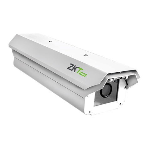
ZKTeco PS-55B Series User manual

Contents 1
USER MANUAL
Network Speed Dome
Version: 1.0
Date: June 2018


WARNINGS AND CAUTIONS
WARNING
TO REDUCE THE RISK OF FIRE OR ELECTRIC SHOCK, DO NOT EXPOSE THIS PRODUCT TO RAIN OR MOISTURE. DO
NOT INSERT ANY METALLIC OBJECTS THROUGH VENTILATION GRILLS OR OPENINGS ON THE EQUIPMENT.
CAUTION
EXPLANATION OF GRAPHICAL SYMBOLS
The lighting flash with arrowhead symbol, within an equilateral triangle, is intended to alert the user the
presence of non-insulated “dangerous voltage” within the product’s enclosure that maybe of sufficient
magnitude to constitute a risk of electric shock to different persons.
The exclamation point within an equilateral triangle, is intended to alert the user the presence of
important operating and maintenance (servicing) instructions in the literature accompanying this
product

2 2.4 Inch TFT POE Terminal User Manual
PRECAUTIONS:
Persons without technical qualifications should not attempt to operate this dome device before
reading this manual thoroughly.
Remove any power to the dome before attempting any operations or adjustments inside the
dome cover to avoid potential damage to the mechanism.
Inside the dome cover there are precision optical and electrical devices. Heavy pressure, shock
and other sudden adjustments or operations should be avoided. Otherwise, you may cause
irreparable damage to the product.
Please DO NOT remove or disassemble any internal parts of the video camera to avoid normal
operation and possibly void the warranty. There are no serviceable parts inside the camera.
All electrical connections to the dome should be made in strict accordance with the attached
labels and wiring instructions in this manual. Failure to do so may damage the dome beyond
repair and void the warranty.
For outdoor installation especially in high places or poles, it is highly recommended that the
proper lightning arrestors and surge suppressors are installed before the dome is entered into
service.
Please do not use the product under circumstances where the limits exceed the maximum
specified temperature, humidity or power supply specifications.
First please set the network data after login. The gateway address is the one to connect the IP
camera.
IP address should be different from other devices’IP address. Otherwise, video is not available.

IMPORTANT SAFEGUARDS
1. Read these instructions before attempting installation or operation of dome device.
2. Keep these instructions for future reference.
3. Heed all warnings and adhere to electrical specifications follow all instructions.
4. Clean only with non abrasive dry cotton cloth, lint free and approved acrylic cleaners.
5. Should the lens of the camera become dirty, use special lens cleaning cloth and solution to properly clean it.
6. Do not block any ventilation openings. Install in accordance with manufacturer’s instructions.
7. Use only attachments or accessories specified by the manufacturer.
8. Verify that the surface you are planning to use for attaching the dome can adequately support the weight of
the device and mounting hardware.
9. Protect this device against lighting storms with proper power supplies.
10. Refer all servicing to qualified service personnel. Servicing is required when the device has been damaged in
any way, when liquid traces are present, or the presence of loose objects is evident or if the device does not
function properly, or has received sever impact or has been dropped accidentally.
11. Indoor dome is for indoor use only and not suitable for outdoor or high humidity locations. Do not use this
product under circumstances exceeding specified temperature and humidity ratings.
12. Avoid pointing the camera directly to the sun or other extremely bright objects for prolonged period of time
avoiding the risk of permanent damages to the imaging sensor.
13. The attached instructions are for use by qualified personnel only. To reduce the risks of electric shock do not
perform any servicing other than contained in the operating instructions unless you are qualified to do so.
14. During usage, user should abide by all electrical safety standards and adhere to electrical specifications for the
operation of the dome.
15. Use supplied power supply transformer only.


Contents I
INDEX
WARNINGS AND CAUTIONS .................................................................................................................................................1
WARNING...........................................................................................................................................................................1
CAUTION ............................................................................................................................................................................1
EXPLANATION OF GRAPHICAL SYMBOLS..............................................................................................................1
PRECAUTIONS: .................................................................................................................................................................2
IMPORTANT SAFEGUARDS ..........................................................................................................................................3
1 Product Introduction...........................................................................................................................................................1
1.1 Package Contents....................................................................................................................................................1
1.2 Specification ..............................................................................................................................................................2
1.3 Performance Features............................................................................................................................................4
2 Installation ...............................................................................................................................................................................5
2.1 Dimension ..................................................................................................................................................................5
2.2 Installation..................................................................................................................................................................6
2.2.1 Wall Mounted..................................................................................................................................... 6
2.2.2 Corner Mounted................................................................................................................................ 7
2.2.3 Pole Mounted..................................................................................................................................... 9
2.2.4 Ceiling Mounted .............................................................................................................................10
2.3 Connection.............................................................................................................................................................. 12
2.3.1 PTZ Connection Way .....................................................................................................................12
2.3.2 Connecting the Device .................................................................................................................12
2.3.3 Setting the IE Browser...................................................................................................................12
2.3.4 Install Video Software....................................................................................................................13
2.4 Login IE Interface .................................................................................................................................................. 15
2.5 Browser..................................................................................................................................................................... 17
2.5.1 Video Browsing................................................................................................................................17
2.5.2 PTZ Control .......................................................................................................................................17
2.5.3 PTZ Function.....................................................................................................................................18
2.5.4 Common Shortcuts........................................................................................................................19

II 2.4 Inch TFT POE Terminal User Manual
2.6 Setting....................................................................................................................................................................... 20
2.6.1 System ................................................................................................................................................20
2.6.2 Network..............................................................................................................................................23
2.6.3 Management Software .................................................................................................................28
2.6.4 IP Cameras.........................................................................................................................................28
2.6.5 Audio & Video ..................................................................................................................................33
2.6.6 PTZ Function.....................................................................................................................................37
2.6.7 Alarm...................................................................................................................................................39
2.6.8 User......................................................................................................................................................40
2.6.9 log.........................................................................................................................................................41
3. Function Instruction......................................................................................................................................................... 42
3.1 Basic Function........................................................................................................................................................ 42
3.2 Special Function.................................................................................................................................................... 43
Appendix I Anti-lightning, Anti-surge ........................................................................................................................... 44
Appendix II Clean Transparent Cover ............................................................................................................................ 45
Appendix III Exception Handling..................................................................................................................................... 46
Copyright Statement............................................................................................................................................................ 47
* Indicates the functions with default protocol, it might not function by using other protocols
※Indicates the optional functions, only with certain mode

1 Product Introduction 1
1 Product Introduction
1.1 Package Contents
IP IR Speed dome 1pc
Wall mount bracket 1pc
Power supply 1pc
Screws kits 1pc
User manual 1pc
CD ( with CMS etc.) 1pc

2 2.4 Inch TFT POE Terminal User Manual
1.2 Specification
Image Sensor 1/3’’ SONY CMOS
Preview video resolution 1920×1080
Mini Illumination Color:0.5Lux B/W:0.05Lux IR ON:0Lux
Signal Noise Ratio ≥50dB
Focus Auto/Manual
D/N IR-Cut
F-Stop F1.6(color),F1.8(IR on),Auto
Close-up INF(Color),1000mm(Far )
Horizontal Rotation Range & Speed Range:360° ,Speed:0.02~480°/s
Tilt Rotation Range & Speed Range:93° ,Speed:0.02~160°/s
360°Scan 1-64 grades setting available
Go to Preset Speed 01-64 levels available
Guard Tours 8 groups, Max.16 points, dwell time user selectable
Pattern Scan 4 pcs
Park Time 1-60mins available
PWR On Action Memory/Pattern 1/Tour 1/360° scan/A-B scan/Park 1/None
Operation menu Multiple languages for OSD menu, English, Italian, Spanish etc.;
Time Scheduling Function 6 tasks
Presets 220
Power off Memory Support
Video output RJ45 10/100M Ethernet
Mini Delay Time 0.18s

1 Product Introduction 3
Frame rate
60Hz:30fps(1920×1080/432×240)
60Hz:30fps(1280×720/432×240)
Compressed Image Format H.264/MPEG-4
Communication Protocol
TCP/IP,HTTP,NTP,IGMP,DHCP,UDP,SMTP,RTP,RTSP,ARP,DDNS,D
NS,HTTPS,P2P
Compressed Image Rate 500Kbps~7Mbps
Power DC 12V-4A
Back End Record Mode PDVR, PC, Megapixel HD system card, NVR, IP-SAN
Power Consumption ≤ 25W
Operating Temperature Indoor: 0°~ +40° Outdoor: -40°~ +60°
Operating Humidity ≤95% Non Condensing
Weight 4~8kg
Protection IP66,Transient voltage 6000V

4 2.4 Inch TFT POE Terminal User Manual
1.3 Performance Features
Use high performance 1/3”CMOS, great low light performance.
Support high definition resolution 1280x720P / 1920×1080P.
10x / 18x / 30x / 36x zoom as optional.
IR distance reach up to 50m (10x)-180m (20x-36x).
Dual-stream output.
Support ONVIF protocol.

2 Installation 5
2 Installation
2.1 Dimension
Ceiling Installation
Bracket Installation

6 2.4 Inch TFT POE Terminal User Manual
2.2 Installation
2.2.1 Wall Mounted
Installation conditions:
Wall mounted dome can be used in the hard wall structure whose thickness should be enough to install
expansion bolt in indoor and outdoor environment. The wall can bear at least 4 times the weight of the
dome. Install wall hanging bracket:
a. As shown in fig 2.3, with the installation holes in the underside of the wall hanging bracket as pattern,
draw punched locations and punch.
Fig 2.3

2 Installation 7
b. As shown in fig 2.4, fix the wall hanging bracket on the wall with wire and cable through it.
Fig 2.4
2.2.2 Corner Mounted
Installation conditions:
Corner mounted dome can be used in the hard wall structure with an angle of 90° whose thickness
should be enough to install expansion bolt in indoor and outdoor environment. The wall can bear at least
4 times the weight of the dome. Install corner mounted attachment and wall hanging bracket:
a. As shown in fig 2.5, with the installation holes in the corner mounted attachment as pattern, draw
punched locations on the wall with an angle of 90°and punch to install expansion bolt.
Fig 2.5

8 2.4 Inch TFT POE Terminal User Manual
b. As shown in fig 2.6, use M8 screw nut to fix the base of corner mounted on the wall with all cables
through the center holes of the corner mounted, marine glue and bracket. Enough wiring length should
be left.
Fig 2.6
c. As shown in fig 2.7, fix the wall hanging bracket with all cables power through it on the corner
mounted attachment.
Fig 2.7

2 Installation 9
2.2.3 Pole Mounted
Installation conditions:
Pole mounted dome can be used in the hard pole structure in indoor and outdoor environment whose
diameter should match the installation size of stainless hose clamps. Factory default is 6 inches stainless
hose clamps (fit φ130-152mm pillar). The pole structure can bear at least 4 times the weight of the dome.
Install corner mounted attachment and wall hanging bracket:
a. As shown in fig 2.8, use the stainless hose clamps to fix the pole mounted attachment with all cable
through it on the pole structure.
Fig 2.8
b. As shown in fig 2.9, fix the wall hanging bracket with all cables through it on the pole mounted
attachment.
Fig 2.9

10 2.4 Inch TFT POE Terminal User Manual
2.2.4 Ceiling Mounted
Installation conditions:
Ceiling mounted dome with thick pole can be used in the hard ceiling structure whose thickness should
be enough to install expansion bolt in indoor and outdoor environment. The ceiling can bear at least 4
times the weight of the dome. Install the base of ceiling and boom:
a. As shown in fig 2.10, with the installation holes in the base of ceiling as pattern, draw punched
locations in the ceiling and punch to install M6 expansion bolt.
Fig 2.10
b. As shown in fig 2.11, at first unscrew the M4 screw at the side of the base of ceiling and split the base
of ceiling and boom. Then make the three groups of cables of power, video/control and alarming into
the side recessing seal groove of the ceiling connector bottom and through the core hole of the base of
ceiling mounted. Fix the base of hang ceiling on the ceiling board.
Fig 2.11

2 Installation 11
Note: If the dome is used in the outdoor conditions, use the silica gel on the faying surface of the base
of hang ceiling and the ceiling board and around the out-holes to be sure water proof
c. As shown in the fig 2.12, tighten the boom with electrical wire and cable through it on the base of
ceiling and screw up the M4 screw.
Fig 2.12
Note: If the dome is used in the outdoor conditions, after using enough raw materials to wrap the
thread at the upper end of boom, tighten the boom on the base of ceiling. Use the silica gel around the
joint sleeve and connector of the boom to be sure water proof

12 2.4 Inch TFT POE Terminal User Manual
2.3 Connection
2.3.1 PTZ Connection Way
Before connecting, please turn off the power and read carefully the instructions of all connected devices.
2.3.2 Connecting the Device
The device can be directly connected to the computer and the network;
Please use the cross-over cable when connecting to the computer;
Please use the straight through cable when connecting to the network.
Note: Please check the power cables are solid or not when connecting the power supply.
2.3.3 Setting the IE Browser
User can browse the video through IE, HVMS or other software, while ActiveX is required to install.
Otherwise, video is not available. And, user is supposed to set the IE security level before downloading
the plug-in.
1. From menu, click “tool”, then choose “Internet options”.
2. Then click “Security” as the follows:
This manual suits for next models
12
Table of contents
Other ZKTeco Security Camera manuals

ZKTeco
ZKTeco ZN-T1 User manual

ZKTeco
ZKTeco ZK-LPR Car ID User manual

ZKTeco
ZKTeco ZKSD4 Series User manual

ZKTeco
ZKTeco FC700 Instruction sheet

ZKTeco
ZKTeco LPRC300 User manual

ZKTeco
ZKTeco LPRC200-4G User manual

ZKTeco
ZKTeco 8000 Series User manual

ZKTeco
ZKTeco biocam series User manual

ZKTeco
ZKTeco MD532 User manual

ZKTeco
ZKTeco 8000 Series User manual