Page 12
HYDRANTS
ZURN INDUSTRIES, LLC Specification Drainage Operation , 1801 Pittsburgh Avenue, Erie, PA 16502, 855.663.9876 Form No. ZMKTG210-15, 7/18
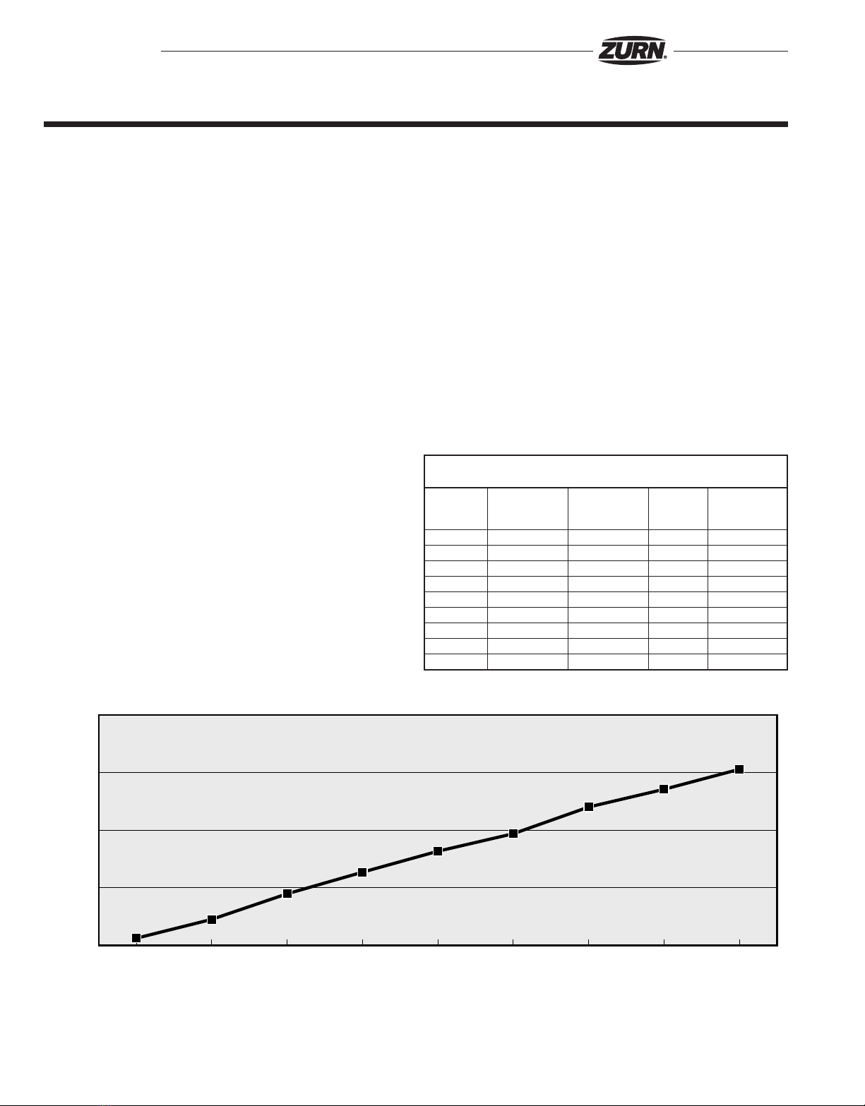
Z1300 Ecolotrol Wall Hydrant –
3/4” Hose Connection
Static Running Inlet Running Outlet Pressure Drop
Pressure Pressure Pressure Flow Rate Across Unit
(psi) (psi) (psi) (gpm) (psi)
10 3.1 0.1 2.8 3.0
20 11.3 1.0 6.0 10.3
30 22.4 1.7 7.3 20.7
40 31.8 2.5 8.6 29.4
50 40.9 3.2 9.7 37.7
60 48.5 3.9 10.6 44.6
70 60.1 7.9 12.2 52.2
80 67.8 9.5 13.3 58.2
90 76.5 10.7 14.4 65.8
Z1300 ECOLOTROL WALL HYDRANT Service Guide
0
50
100
10 20 30 40 50 60 70 80 90
10.3
20.7
29.4
37.7
44.6
52.2
58.2
65.8
6.0
7.3
8.6
9.7
10.6
12.2
13.3
14.4
3.0
2.8
Running Inlet Pressure (psi)
Static Inlet Pressure (psi)
Pressure Drop Across Unit (psi)
Flow Rate (gpm)
Z1300 Service Guide
Step 1: Shutting Off the Water Supply to the Hydrant
Locate the supply shut-off valve and rotate until water supply is off.
Step 2: Removing the Faceplate and Adjacent Components
Using 1/8” Allen wrench, remove the five faceplate screws (24) from head (1)
by turning counterclockwise. Remove the faceplate (20), and nozzle (19).
If the Equa-Balance®seal was not the reason for service – skip to step 4.
Step 3: Replacing the Equa-Balance®Seal
Remove the current Equa-Balance® seal (23). Check seal for damage
(punctures, rips, etc.). Replace damaged seal with a new seal (23) observing
proper orientation (EQUA-BALANCE®SEAL SHOULD CUP INWARD IN ITS
REPLACED STATE.)
Step 4: Removing the Internal Operating Assembly
The internal operating assembly (4-8, 10-12, and 25-26) can be removed by
gripping the square end of the operating screw (5) with a pair of pliers and
pulling straight out.
If the operating screw O-Ring was not the reason for service – skip to step 6.
Step 5: Replacing the Operating Screw O-Ring
Remove the operating screw (5) from operating coupling (7) by turning
clockwise and slip the old O-Ring (6) off, and replace with new O-Ring (6).
Reinstall operating screw (5) into operating coupling (7) by turning counter-
clockwise. (Note: Lubricate the operating screw (5) threads and the O-Ring
(6) with Lubriplate FGL-2 if needed.)
If the operating screw assembly was not the reason for service – skip to
step 7.
Step 6: Checking Operating Screw Assembly
Remove the operating screw (5) from the operating coupling (7) by turning
clockwise, and using 5/32 Allen wrench, remove setscrew (4) by turning
counterclockwise, remove stainless steel ball (26) and check orientation of
O-Ring (25). If not seated properly, reseat, replace the ball (26) and replace
setscrew (4) using Allen wrench and turning clockwise until flush with
operating screw (5) or until tight and flush with operating screw (5).
(Note: Lubricate and reinstall as in step 5.)
If the hydrant shutoff washer was not the reason for service – skip to step 8.
Step 7: Replacing the Hydrant Shutoff Washer
Remove #10-24 NC x 3/8 screw (12) using a flat screwdriver and turning
screw (12) counterclockwise, remove washer (11) and replace with new
washer (11) and new screw (12) turning screw clockwise until tight.
Step 8: Replacing the Internal Operating Assembly
There is a flat or a V-notched boss inside of the hydrant head (1) that keeps
the operating coupling (7) from rotating when hydrant is turned on and off.
With operating screw (5) turned counterclockwise into operating coupling (7)
until it stops, and making sure that a flat side or corner of operating coupling
(7) lines up with appropriate boss, reinsert the internal operating assembly
into the hydrant.
Step 9: Replacing the Wall Plate
Insert nozzle (19) into place and fasten the faceplate (20) to head (1) using
the 1/8” Allen wrench and the five faceplate screws (24). Rotate the screws
clockwise until screws are snugged tight. (By hand only!)
Step 10: Turning On the Water Supply
Locate the water supply shut-off valve and rotate until water supply is on.
Z1300 Ecolotrol Wall Hydrant – 3/4” Hose Connection