FV251 Rev. B 7/9/18
Page 6
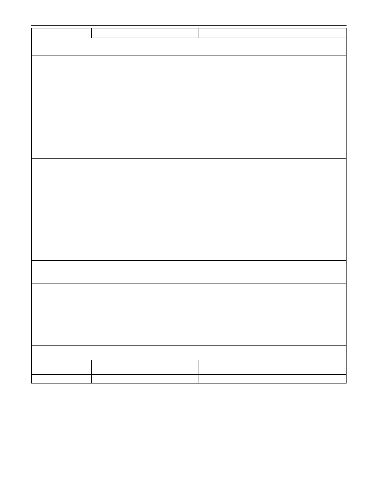
Aquaush Trouble Shooting Guide
Care of Chrome plated surfaces.
The suggested cleaning of chrome plated surfaces is simply to clean them with soap and water then dry. Commercial cleaning compounds are
never recommended.
Seasonal use.
Valves usein installations subject to shut down because of cold and freezing conditions should be maintained in the following manner. After the
main supply has been shut off and the water drained from the systim, remove the stop valve cap and stop internals to allow the water to drain from
the ush valve itself.
*see previous for numerical references.
Problem Cause* Correcve Acon*
Valve will not operate. 1.) Stop valve is closed. 1.) Open stop valve.
2.) Supply valve is closed. 2.) Open supply valve.
Insucient volume of water
to adequately siphon xture.
1.) Stop valve is not open enough. 1.) Open stop valve for desired volume of water.
2.) Urinal trip mechanism installed in wrong kit,
urinal or closet
2.) Replace urinal part with proper closet valve part.
3.) Insucient volume or pressure at supply. 3.) If gauges are not available to measure supply pressure or volume of
water at the valve, completely remove the working parts and open
the stop valve to allow water to pass through the empty valve. If the
supply is adequate to siphon the xture, the guide ring (#16) may be
removed from the guide assembly to provide addional ow. Should
this prove unsasfactory, steps should be taken to increase the pres-
sure and/or supply.
Flush valve shuts o too
quickly.
1.) Damaged or punctured diaphragm. 1.) Install new P6000-EUR replacement kit to remedy the problem.
2.) Enlarged by-pass orice. 2.) Install new P6000-ECR, P6000-EUR replacement kit to remedy the
problem.
Valve is short ushing. 1.) Cylinder guide assembly and diaphragm assem-
bly are not ght.
1.) Screw the two assemblies hand ght.
2.) Enlarged by-pass orice. 2.) Install new P6000-ECR, P6000-EUR replacement kit to remedy the
problem
3.) Urinal trip mechanism (black #12) in closet ush
valves.
3.) Install closet trip mechanism(white) .
Valve is ushing too long or
not shung o.
1.) Trip mechanism not seang properly due to
foreign material between trip mechanism and
retainer disc.
1.) Disassemble parts and rinse thoroughly.
2.) By-pass orice is plugged or parally plugged. 2.) Examine by-pass orice and clean if necessary being certain not to
enlarge orice opening.
3.) Line pressure is not adequate to force trip mech-
anism to seal.
3.) Pressure is inadequate or has dropped below minimum operang
range. Steps should be taken to increase the line pressure.
4.) Cracked cover. 4.) Replace cover with new one.
Water splashes out of xture. 1.) Supply volume is more than is necessary. 1.) Adjust downward on control stop.
2.) Lime accumulaon on vortex or spreader holes
of xture.
2.) Remove the lime build up.
Flush is not considered quiet. 1.) Control stop may not be adjusted for quiet
operaon.
1.) Adjust the control stop for quiet operaon keeping in mind the xture
evacuaon requirements.
2.) Fixture may be contribung to noise. 2.) Check noise created by xture by placing a cover over the bowl open-
ing to separate valve noise from bowl noise. If it is determined the
xture is too noisy consult with xture manufacturer.
3.) Piping system may be source of noise 3.) High pressure in the system can somemes be controlled by the stop
valve. Other sources of noise may be the absence of air chambers and
shock arrestors, loose pipes, improper size pipes, etc. In these cases
the building engineer should be consulted.
Chaering noise in ush
valve.
1.) Segment diaphragm (#14) has been installed
upside down.
1.) Reposion segment diaphragm as instructed by the markings on the
diaphragm (”this side down”).
2.) The inside cover has been distorted by freezing
or abuse.
2.) Replace both inside plasc cover and outside brass cover.
Handle assembly leaking. 1.) Handle assembly is not ght. 1.) Tighten handle assembly.