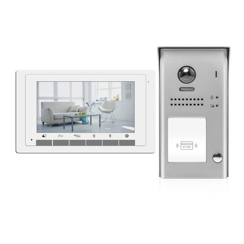
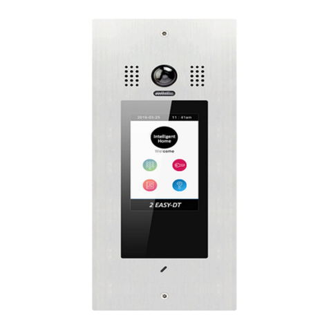
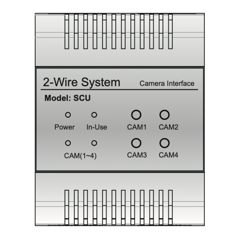
2easy 2-wire Series User manual

DT821 TECHNICAL MANUAL
Apartment Intercom System
2-wire Series
VULCAN
A B A B
112233
00##
778899
445566
821-VD
821-TFT
821-AD
821-LB
821-DR
821-BL
821-MK
821-S0 821-T5
821-S4

2 EASY
-2-
1. Parts and Functions
L1 L2
1 2 3 4 5 6
ON DIP
Fisheye Lens
Speaker
Night View LED
Card Reader
Dot-matrix Display
Status Indicator
Microphone
Screw Hole
MK Module
Connection
Port
A B
Door Station
Flush mount wall boxSurface mount box
INSTALLATION GUIDE

2 EASY
-3-
2. Terminal Description
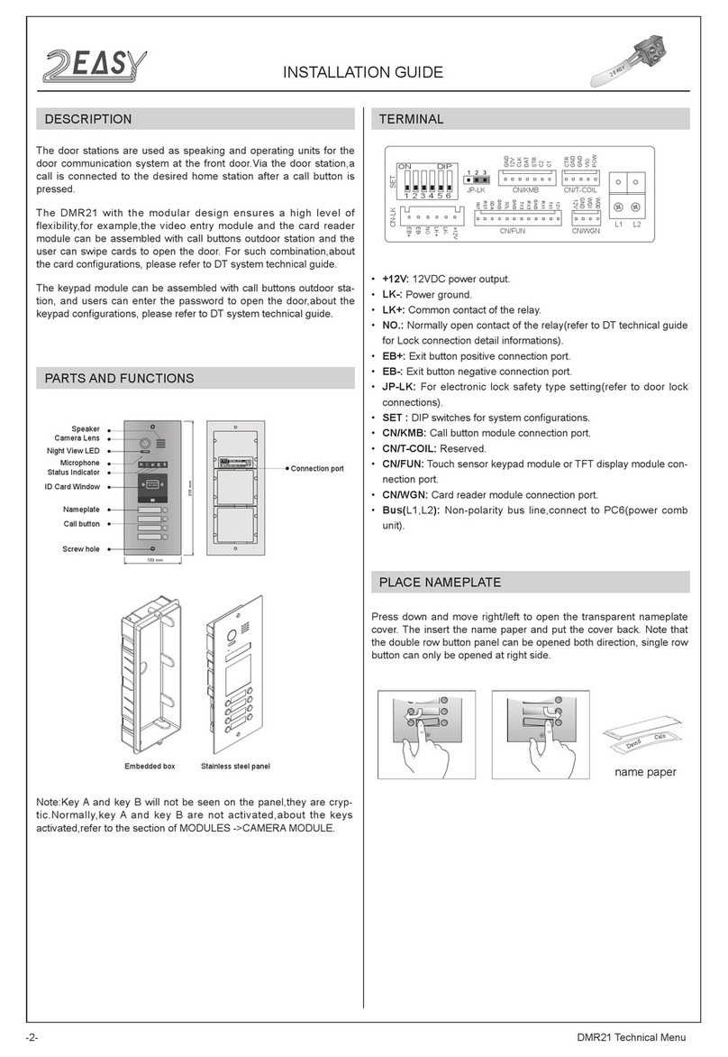
• +12V: 12VDC power output
• LK-: power ground
• LK+: relay common contact
• NO.: relay normally open contact
• EB+: exit button positive
• EB-: exit button negative
• JP-LK: electronic lock type setting
• SET :DIPswitchesforsystemconguration
• CN/KMB: additional bell button connection port
• CN/T-COIL: reserved
• CN/FUN: Mechanical keypad module or TFT display module connection port
• CN/WGN: Card reader module connection port
• Bus(L1,L2): no-polarity bus line,connect to PC7(power supply)
CN-LK
JP-LK
LK-
+12V
LK+
NO
EB-
EB+
SET
12V
TX1
RX1
GND
RX3
TX3
GND
5CL
GND
5DA
RST
INT
GND
12V
CLK
DAT
STR
C2
C1
CTR
GND
GND
VIO
POW
WG0
WG1
GND
12V
CN/KMB CN/T-COIL
CN/FUN CN/WGN
L1 L2
1 2 3 4 5 6
ON DIP
3. Specication
Power supply: 24Vdc(supplied by PC7)
Camera:1/2.7’’sheyecamera,170owide angle
Power Consumption: 1W standby
5W working
Card Reader: Support 125KHz and 13.56MHz unencrypted RFID tag
Unlock Power output: 12Vdc,250mA
INSTALLATION GUIDE

2 EASY
-4-
4. Mounting
INSTALLATION GUIDE
Flush mounting
Surface mounting
1 2 34
Cut a hole and install the wall box Final result
Use screws to fasten the panel
Connect and plug bus line connector with cable
1 2 34
Unlock timing: 1~99s
Working temperature: - 20ºC ~ +55ºC
Wiring: 2 wires (no-polarity)
Dimension: H316×W133×D48mm(3-Modules)
H232×W133×D48mm(2-Modules)

Code=0
OFF ON
OFF ON
DBC4A
A B C D
DBC4A
A B C D
Impedance
switch
Impedance
switch
Code=2
Code=1
Code=3
Code=28
Code=30
Code=29
Code=31
5. Connection Diagram
-5-

2 EASY
-6-
VD MODULE
1. DIP Switches Settings
There are 6DIP-switches on the rear ofdoor station.The switches can be modified either before or
after installation,but restartingthe power is needed whenever the switches have been modified
ON(1)
=
OFF(0)
=
ON
ON
ON
123456
• DIP-1 and DIP-2 are for door station ID setting. When multiple door stations are installed,the first
door station address is 00 (default), the second door station address is 01: DIP-2 is On,the third
door station address is 10: DIP-1 in On,the fourth door station address is 11: DIP-1 and DIP-2 are
On
• DIP-3 is for single or double row button door station selection.Ifthe door station is a double row
button,such as DMR21-D8, set this bit to 0. For single row button door station,set to 1
6. VD (VIDEO) Module
Note: Key A and key B can not be seen on the panel, they are cryptic.
Normally, key A and key B are not active. To activate them, flip DIP
switch 6 into On position
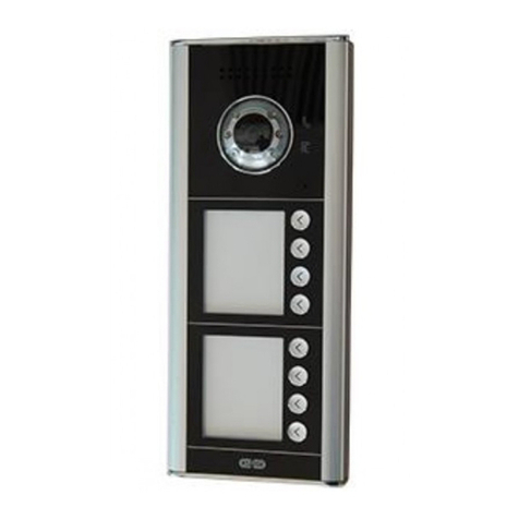
Speaker
Camera lens
Night view LED
MIC
Invisible key A
Status indicator
Talk indicator
Unlock indicator
Invisible key B
-5-

2 EASY
-7-
Remember to power Off and power On the door station and then flip
DIP-6 ON to perform following settings:
1. Press Key A, Unlock Indicator turns on with double beep sound
2. Press Key A again to set the Unlocking Mode to Normally Open or Normally Closed
Normally Open: Status Indicator blinks once with beep sound
Normally Closed: Status Indicator blinks twice with beep sound
If door station has TFT screen connected, current Unlocking Mode will be visible on the screen
• Unlocking Mode Setting
2. Settings via Invisible Keys A and B
• DIP-4 is for button code selection for Door Stations with buttons.All Buttons are pre-programmed
with User Code/Address (see page 15). Ifyou planningto use factory programming, keep DIP-4
Off. When factory programminggoingto be modified,change DIP-4 to On position
• DIP-5 is for unlockingtime quicksetting. Off(0) is the default setting, and the default time is 1
second.Ifset On(1), the unlocktime is 5seconds (Different unlocktime can be programmed,
DIP-5 should be in On position for different times)
• DIP-6 is for activatinginvisible key A and key B. Power Off door station and power On, then flip
DIP-6 into On position. Remember to flip Off after programming finished.
VD MODULE
2 EASY
-8-
1. Press Key A,Unlock Indicator turns on with double beep sound
2. Press and hold Key Bto change unlockingtime from default 1s.Every beep and/or flash of
StatusIndicator increase unlockingtime by second.Ifdoor station has TFTscreen connected,time
increase will be visible on the screen
• Unlocking Time Setting
VD MODULE
1. Press and hold Key A for 3 seconds to enter the RingtoneOption Mode, the StatusIndicator
turns on and the current Ringtone will be played.
There are 3 options to choose from:
00 - Mute; 01 - Tune (default); 02- English (voice Annunciation)-Deafult
2. Press key A to select
3. Press Key B to exit
• Ringtone Setting

2 EASY
-9-
VD MODULE
1. Press Key Bto enter RingtoneVolumeSetting,the Talk Indicator turns on and plays the tune at
the current volume
2. Press Key A to increase/decrease volume
3. Press Key Bto exit
Ifdoor station has TFTscreen connected,the current Volumeand changes will be visible on the
screen
• Ringtone Volume Setting
1. During conversation, press and hold Key B for 3 seconds to enter the Talk VolumeSetting
The Talk Indicatorturns on with beep sound
2. Press Key A to increase/decrease volume
3. Press Key B to exit
• Talk Volume Setting

2 EASY
-10-
VD MODULE
1. Press Key A, the Talk Indicatorand StatusIndicatorturns on with double beep sound
2, Press Key A again to enter the Camera NTSC/PALsetting.
PAL(Default): the Status indicator blinks ones with beep sound
NTSC: the Status indicator blinks twice with double beep sound
• Camera NTSC / PAL Settings
1. Press Key A, the Talk Indicatorand StatusIndicatorturns on with double beep sound
2. Press Key B to enter Enable/Disable ImageZoom Mode settings.
Enable ImageZoom Mode (Default): the Talk indicator blinks ones with the beep sound
Disable ImageZoom Mode: the Talk indicator blinks twice with double beep sound
Door Station is equipped with Fisheye camera. EnabledImage Zoom Mode, allows monitor to
display image on full screen for 5 seconds, then switch to zoomed image. Not all monitors have
Zoom Pan&Tilt option, so those without, should be used with disabled Image Zoom Mode. Othewise
image will be flickering, trying to zoom.
• Enable/Disable Image Zoom Mode

2 EASY
-11-
To be able to change any default settings go first into Programming Mode by typing in
Default Master Code 1234 #
and type in the corresponding codes. Touch to exit the Setting Mode
MK MODULE
Parameters Setting
Setting items Setting range Default
value
Setting
code
Reset all settings 1,2,3,4 -00
Setting the master code 1 ~ 12 digits
Valid keys:0 ~ 9 1234 01
• The Defaults are: ascancelbuttonand#asconrmbutton
• # “confirm”button should be used after every change made
•If no activity for 10sec, system exits Programming Mode automatically
112233
00##
778899
445566
Mechanical
keypad Connect to main
or last module
Connect to next
module
IN
OUT
7. MK (MECHANICAL KEYPAD) Module
Programming Codes Tables

2 EASY
-12-
MK MODULE
Setting items Setting range Default Setting
code
Setting the key
illumination time
10 to 99 seconds/
continually lit 10 seconds 02
Setting the unlock time 01 to 99 seconds 1 second03
Setting the unlock mode 0:opened/1:closed open 04
Operation tone settings 0,1,2 on 05
Reset code settings 1,2,3,4 - 06
&# function settings 0:Normal/1:Reverse Normal 07
Call tone settings 0:Enable/1:Disable Enable 08
SPK Adjustment Valid keys:0~9 5 11
Night light level Valid keys:0 ~ 5 4 13
Reserve Reserve Reserve 14~17
Setting the code
forTemporary1
1 ~ 12 digits
Valid keys:0~9 - 18
Setting the code
forTemporary2
1 ~ 12 digits
Valid keys:0~9 - 19
Setting the code for
user group1
1 ~ 12 digits
Number of codes:40
Valid keys:0~9
- 20~59
Setting the code for
user group2
1 ~ 12 digits
Number of codes:40
Valid keys:0~9
- 60~99

2 EASY
-13-
MK MODULE
Input the master code.
Default: ##
- All settings will restore to their
default value
s
-
When power on or activate
‘Reset all settings’,the keypad
checking will carry out, during
this time,the key illumination
will blink and the touch
operation is not possible.
When finished, keys
illumination will stop blinking
and long beep will sound
- The
M
aster
password
is allowed
1~12 digits
. The user password
can not be the same as Master
password. It is recommended that
you change the default Master
password
- The unlock
ing
time can be set
on either
video
monitor
or
door
station, and the valid value is the
number you set last
Beep+, Beep
Beep+, Beep Beep+, Beep Beep+, Beep Beep+, Beep
Beep+ Beep+ Beep+ Beep+
Type in code range:00 or
10~99
Type in code range:01~99
3.Setting the key
illumination time
4.Setting the
unlock time
2.Setting the master code
(Default 1234) (Default 10s) (Default 5s)
Type in new master code
(1~12 digits)
Type in the setting code
Type in
Type in the setting code
1.Reset all settings
00 #
1234 # 4321 #
01 #
10 # 09 #
Type in the setting code
02 #
Type in the setting code
03 #
- If the key illumination time is set
to 00,the key illumination will
stay
lit at all times
- If the key illumination time is set to
10~99,the key illumination will light
up for 10~99 seconds
before
turning off. Default is 10 sec
-
When the “ cancel” key is pressed, the indicator will show its standby color, the buzzer beeps
twice
, and the
system exits the setting mode
-
When there isn’t any operation in 10s, the buzzer beeps
twice
, and the system exits the setting mode
Beep, Beep+
*
-
When setting failure, the buzzer beeps
twice

2 EASY
-14-
Input the master code.
Default: # #
Beep+, Beep Beep+, Beep Beep+, Beep Beep+, Beep
Beep+
Beep+Beep+ Beep+
7.Reset code setting 8. &# function setting6.Setting operation tone
(Default ON) (Default Normal)(Default 0(opened))
Type in the setting code
Type in code
Type in the setting code
5.Setting the unlock mode
04 # 05 #
0:(NO)/1:(NC)
1#
0/1 0/1 0/1
1# 1 #1234 #
Type in the setting code
06 #
Type in the setting code
07 #
0 or 1
Type in code 0 or 1 Type in code Type in code
0:(On) /1:(Off) 0:(normal) /1:(reverse)
*
*
*
- The unlock mode can be set on
either video monitor or door
station, and the valid value is the
number you set last
- When the operation tone is
set to 0, keyboard clicks are
sound
- When the operation tone is
set to 1, keyboard clicks are
silent
- Cancel all passwords except
master password
- Restore the master
password to a default
1,2,3,4
- When is set to 0, button is to
cancel the input, # button to
confirm the input
- When is set to 1, button is to
confirm the input, # button to
cancel
Beep+, Beep
-
When the “ cancel” key is pressed, the indicator will show its standby color, the buzzer beeps
twice
, and the
system exits the setting mode
-
When there isn’t any operation in 10s, the buzzer beeps
twice
, and the system exits the setting mode
Beep, Beep+
*
-
When setting failure, the buzzer beeps
twice
MK MODULE

2 EASY
-15-
Input the master code.
Default: # #
Beep+, Beep
Beep+
Type in the setting code
9. Call tone setting
08 #
0/1
1 #
Type in 0 or 1
0(enable) /1(disable)
(Default enable)
-
If set to 0,
ringtone will be present
when
pressing the “CALL” button
- If set to 1, no r
ingtone
when
pressing the “CALL” button
Beep+, Beep
Beep+
10.SPK volume adjust
setting
Type in the setting code Type in the setting code
11 #
Type in range 0~9
5#
(Default:4)
- Unlock via password is still
available when the door
station i
n
talking
state
- When door station is talking,
you can enter the Master code
(the LED turns white upon that)
to activate the volume adjusting
function:
Speaker adjustment: 3 (up),
6 (down)
Beep+, Beep
Beep+
11.Night light level
setting
13 #
Type in range 0~5
3#
(Default 4)
- Night Light Level:0~5
-The higher the number, the
brighter the lights
Beep+, Beep
-
When the “ cancel” key is pressed, the indicator will show its standby color, the buzzer beeps
twice
, and the
system exits the setting mode
-
When there isn’t any operation in 10s, the buzzer beeps
twice
, and the system exits the setting mode
Beep, Beep+
*
-
When setting failure, the buzzer beeps
twice
MK MODULE

2 EASY
-16-
Input the master code.
Default: ##Beep+, Beep
Beep+, Beep Beep+, Beep Beep+, Beep Beep+, Beep
Beep+ Beep+ Beep+ Beep
Type in code 1~12 digits Type in code 1~12 digits
14.Setting the code
for user group1
15.Setting the code
for user group2
13.Setting the code
forTemporary2
Type in the setting codeType in the setting code
12.Setting the code
forTemporary1
18 # 19 #20 #~ 59 # 60 #~ 99 #
2011 #
Type in code 1~12 digits
1006 #
Type in code 1~12 digits
2010 #2012 #
Type in the setting code Type in the setting code
20~59 60~99
-
The
temporary password
is for one time use and valid for 60 sec
in case first attempt was unsuccessful.
- The temporary1 is used to release the first lock,and the temporary
2 is used to release the second lock(the second lock need
an
additional RLC Lock Control Interface
)
- If the password length exceeds 12 digits, the
keypad module will
make multiple short beep sounds
“beep,beep,beep,beep”
- Failed
- The temporary
password
can not be set the same as the master
password
and
the
user
password
- The user code group1 is used to release the first lock,and the user
code group2 is used to release the second lock (the second lock
need
an additional RLC Lock Control Interface)
- The user code group1 and user code code group2 can contain 40
group passwords
each
- If the password length exceeds 12 digits, the
keypad module will
make multiple short beep sounds
“beep,beep,beep,beep”
- Failed
- The user
password
can not be set the same as the master
passwrd
and temporary
password
-
When the “ cancel” key is pressed, the indicator will show its standby color, the buzzer beeps
twice
, and the
system exits the setting mode
-
When there isn’t any operation in 10s, the buzzer beeps
twice
, and the system exits the setting mode
Beep, Beep+
*
-
When setting failure, the buzzer beeps
twice
MK MODULE

2 EASY
-17-
DR MODULE
Card/keyfob reader
Dot-matrix display
Features
Card/Keyfob Operation
• Up to 320 user cards can be registered by door station
• Easy management with indicators and sounds
• The distance of card reading is 3 to 5 cm
• The Master Cards are necessary when you add or delete user cards. Please
keep them safe for future use
• Creating New Master Cards
a. Power On and join together EB+ and EB- wires. Double beep will sound
b. Toggle DIP4 switch four times. Double beep will sound
c. Show the new, to be Master ADD Card,to the Proximity Reader, single beep will sound
d. Show the new, to be Master DeleteCard, to the Proximity Reader, single beep will sound
Dot-matrix: 16 x 24 dot matrix display
Card Reader: support 125KHz and 13.56MHz unencrypted RFID tags
8. DR (DOT-MATRIX) Module
IN
OUT
Connect to main
or last module
Connect to next
module
VD Module
CN-LK
+12V
LK-
LK+
NO
EB-
EB+
SET
1 2 3 4 5 6
ON DIP
ADD
Ma
ster
Card
Ma
ster
DELETE
Card

2 EASY
-18-
DR MODULE
a. Show the Master ADD card to the Proximity Reader, double beep will sound
b. On Direct Call Button Module, press the Flat button which ID card needs to
be associatedwith (skip if there is no Direct Call Button module)
c.Show all blank ID cards, one by one
d.Repeat stepsb and c for each button
e.Finish with Master Add card
For door stations without Direct Call Buttons
a. Show the Master Add card to the Proximity Reader, double beep will sound
b. Show all blank ID cards/keyfobs, one by one
c. Finish with Master Add card
i) Add User Cards/Keyfobs
ADD
Ma
ster
Card
Users
Card

2 EASY
-19-
DR MODULE
a. In standby mode, show the Master DELETE Card, double beep will sound
b. Show the Master ADD Card, double beep will sound
c. Show the Master DELETECard again single beep will sound. After
approximately 10 sec, it willreturntostandby and all registered cards/keyfobs
will be deleted
iii) Deleting All Not Present Cards at Once
i) By PC- manage cards/fobs via software (coming soon)
ii) By SD Card- Clone registered cards to a new door station (if door station
was replaced for some reason). Power Off and power On the door station, flip
DIP-6 into On position, insert micro SD card and it will backup all registered
cards/keyfobs.
Power On new door station, flip DIP6 into On position, insert SD card and it will
upload Card Database into new door station. Remove SD card, flip DIP6 Off
iiii) Card Database
ii) Delete User Card
a. Show the Master DELETE Card to the Proximity Reader, double beep will
sound
b. For Door Station with Direct Call buttons: if card is not present, press desired
button and all ID cards registered to that flat will be deleted. If card is present,
directly show the card and it will be deleted. If card was not assigned to direct
button, you will need to use procedure iii below
c. Finish with Master DELETE Card
Ma
ster
DELETE
Card
Users
Card

2 EASY
-20-
IN
OUT
S4 MODULE
Call button
Name plate
Call codes
The DT821 automatically assigns the call codes to the connected module’s
buttons. Regardless of the structure of the call button module, the button
numbers are starting from the bottom
9. S4 Module
Connect to main
or last module
S4 Module
address settings
Connect to next
module
04
03
02
01
16
15
14
13
Call Code Call Code Call CodeDIP DIP DIP
08
07
06
05
20
19
18
17
12
11
10
09
24
23
22
21
1 2 3 4 5 6
ON
1 2 3 4 5 6
ON
1234
12341234 1234
5
55 56 6
ON
ONON ON
Other manuals for 2-wire Series
3
This manual suits for next models
12
Other 2easy Intercom System manuals

2easy
2easy DMR12/S8 User manual

2easy
2easy XT24 User manual

2easy
2easy DMR21/D32/F1 User manual

2easy
2easy IRIS/DT39 User manual

2easy
2easy 2-wire Series User manual

2easy
2easy DT-SCU User manual

2easy
2easy CDV4791 User manual

2easy
2easy DK4761 User manual

2easy
2easy DT 2-wire Quick start guide

2easy
2easy 2-wire Series User manual