3DGence INDUSTRY F340 User manual

USER'S MANUAL
3DGence INDUSTRY
F340

page 2 of 70
3DGence INDUSTRY F340 | version 04.2018
Contents
I INTRODUCTION ............................................................................................................................................................................4
1. INTRODUCTION......................................................................................................................................................................4
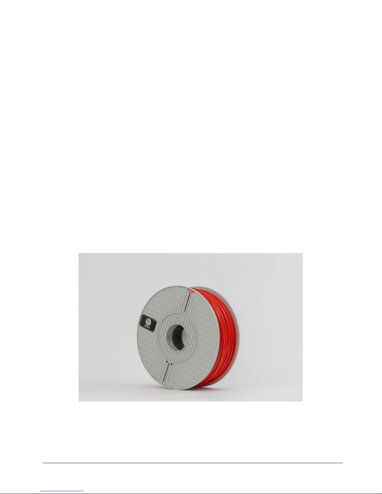
2. PRINTING MATERIALS ............................................................................................................................................................4
3. SYMBOLS ................................................................................................................................................................................5
3.1. Auxiliary symbols used in the User's Manual .................................................................................................................6
4. SAFETY MEASURES.................................................................................................................................................................6
4.1. General information .......................................................................................................................................................6
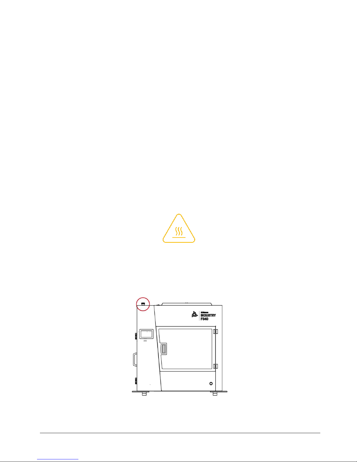
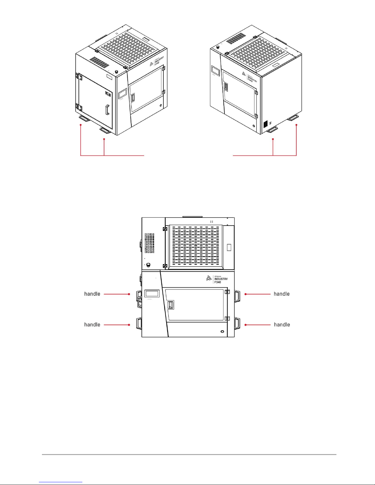
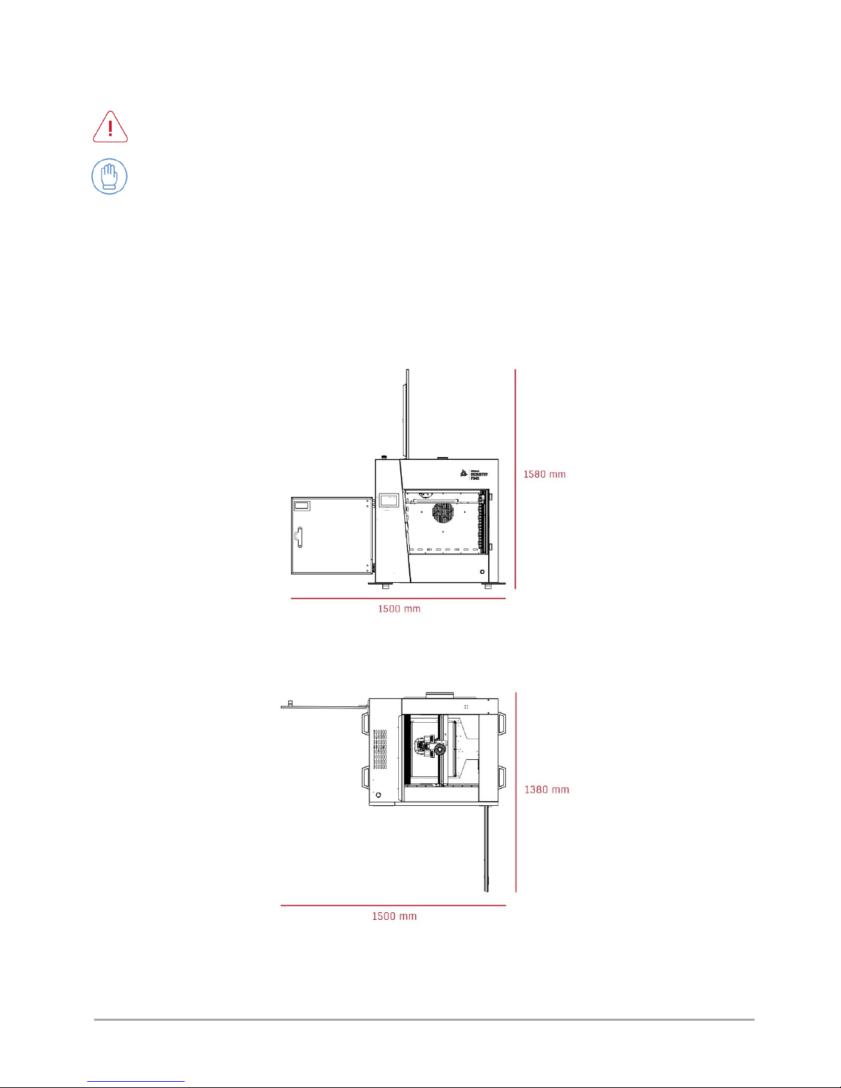
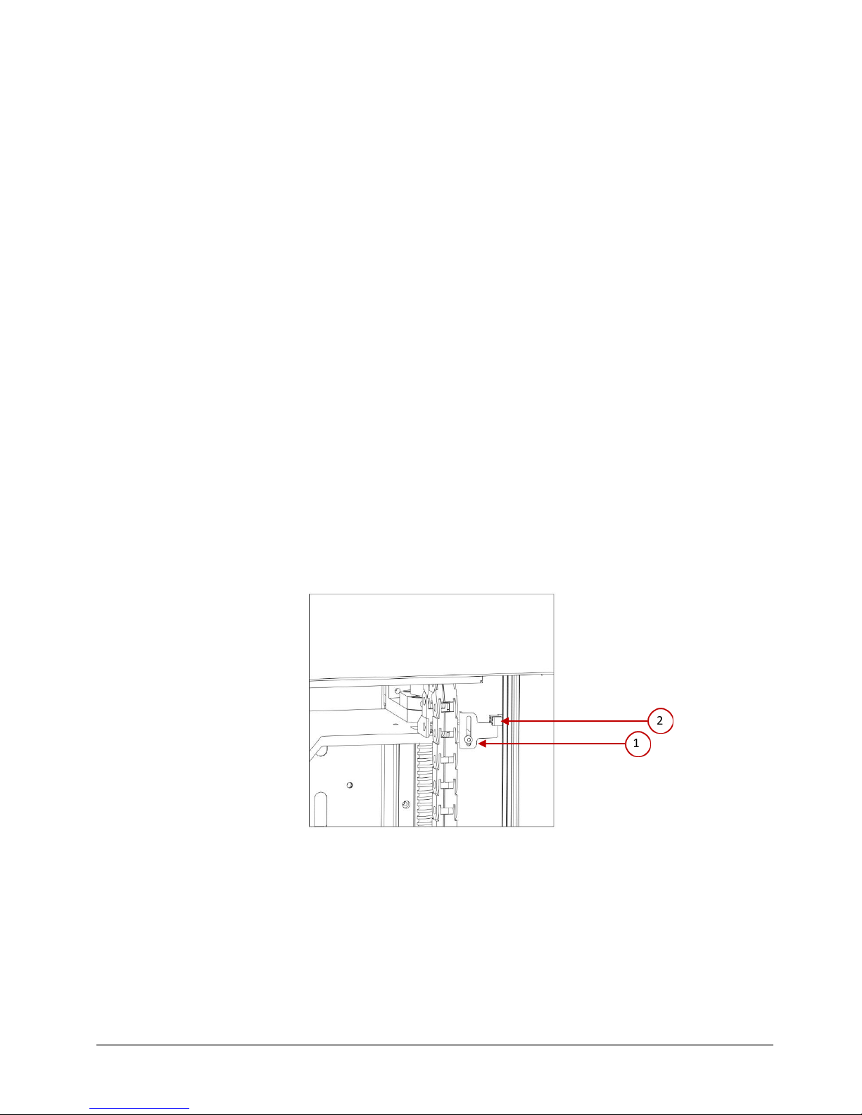
4.2. Relocating the printer.....................................................................................................................................................7
4.3. Choosing proper installation place for the printer .........................................................................................................9
4.3.1. Specification of connection .......................................................................................................................................10
4.4. Before starting the printer............................................................................................................................................10
II PRINTER DESCRIPTION ..............................................................................................................................................................11
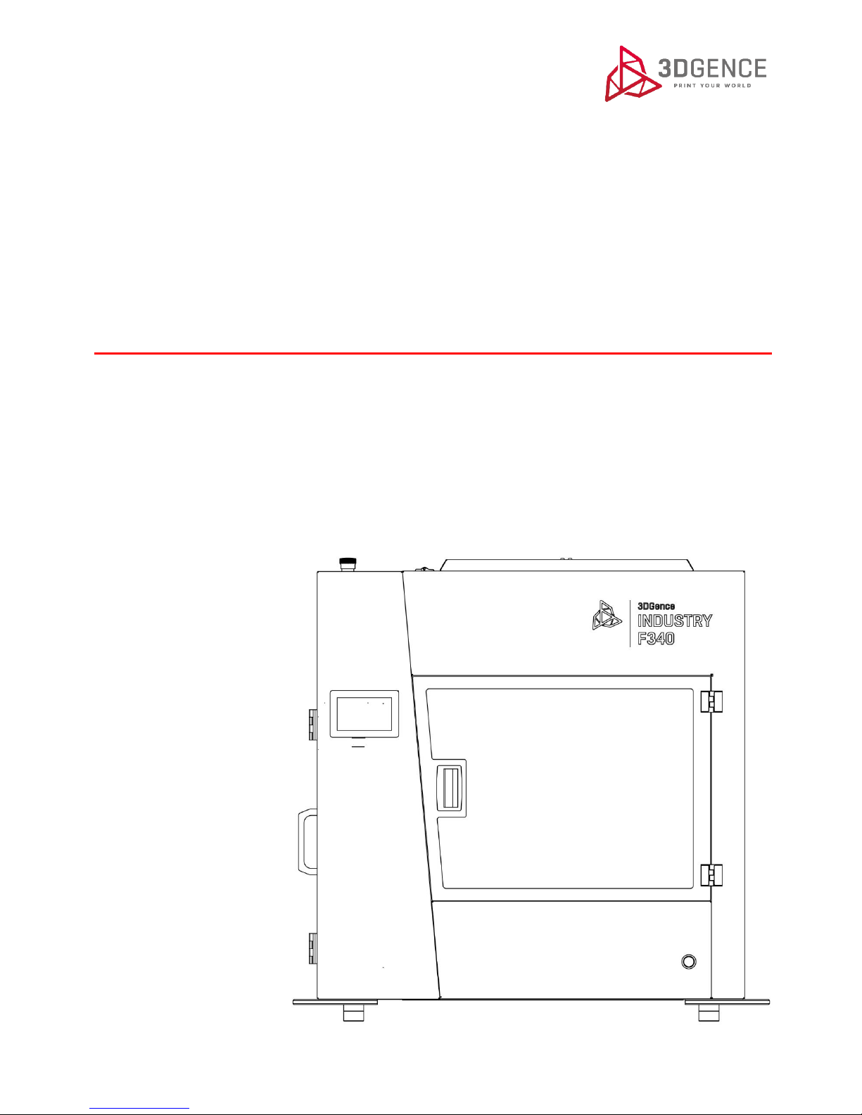
1. DESIGN OF PRINTER .............................................................................................................................................................11
1.1. General description ......................................................................................................................................................11
1.2. Kinematic system..........................................................................................................................................................15
1.3. Heatbed ........................................................................................................................................................................15
1.4. Filament chamber.........................................................................................................................................................16
1.4.1. Adjustment of filament chamber temperature .........................................................................................................16
1.5. Extruder modules .........................................................................................................................................................16
1.6. Dual hotend module .....................................................................................................................................................17
1.7. Printer's power supply management ...........................................................................................................................18
1.7.1. Main switch ...............................................................................................................................................................18
1.7.2. Printer switch.............................................................................................................................................................18
1.7.3. Emergency stop button .............................................................................................................................................18
1.8. Memory card ................................................................................................................................................................19
1.9. Smart Material Manager system ..................................................................................................................................19
2. SET OF PRINTER'S ACCESSORIES ..........................................................................................................................................20
3. USER INTERFACE ..................................................................................................................................................................20
3.1. Idle state menu .............................................................................................................................................................20
3.1.1. MENU screen .............................................................................................................................................................24
3.2. Menu during operation ................................................................................................................................................31
III PREPARATION FOR WORK ........................................................................................................................................................40
1. INSTALLATION OF DRIVERS ..................................................................................................................................................40
1.1. Firmware update ..........................................................................................................................................................40
2. CONNECTING AND STARTING THE PRINTER ........................................................................................................................40
3. HEATBED PREPARATION ......................................................................................................................................................42
3.1. Heatbed calibration ......................................................................................................................................................42

page 3 of 70
3DGence INDUSTRY F340 | version 04.2018
4. ACTIVITIES CONNECTED WITH PRINTING MATERIAL...........................................................................................................43
4.1. Material loading............................................................................................................................................................43
4.2. Material unloading .......................................................................................................................................................44
4.3. Failure to load/unload material....................................................................................................................................45
IV PRINTER OPERATION (FIRST PRINTOUT) ..................................................................................................................................47
1. STARTING A CODE FROM SD CARD ......................................................................................................................................47
2. ASSESSMENT OF THE PRINTER OPERATION QUALITY..........................................................................................................47
3. REMOVING PRINTOUTS FROM THE PRINTER.......................................................................................................................49
4. SMART MATERIAL MANAGER ..............................................................................................................................................50
4.1. Change of material during printing ..............................................................................................................................50
4.2. Depletion of material during printing...........................................................................................................................51
5. CLEANING.............................................................................................................................................................................51
5.1. Hotend cleaning............................................................................................................................................................51
5.2. Heatbed cleaning ..........................................................................................................................................................51
6. SLEEP MODE.........................................................................................................................................................................52
7. SWITCHING THE PRINTER OFF .............................................................................................................................................52
V SOFTWARE ................................................................................................................................................................................53
1. INTRODUCTION....................................................................................................................................................................53
1.1. Quality guarantee .........................................................................................................................................................53
2. INSTALLATION ......................................................................................................................................................................53
VI DUAL HOTEND MODULE ..........................................................................................................................................................54
1. DETAILED DESCRIPTION OF THE MODULE ...........................................................................................................................54
2. INSTALLATION AND CHANGE OF MODULE ..........................................................................................................................55
2.1. Installation of module...................................................................................................................................................55
2.2. Module change .............................................................................................................................................................57
VII COMPLEMENTARY INFORMATION..........................................................................................................................................58
1. AUTOCALIBRATION AND AUTOCOMPENSATION.................................................................................................................58
VIII SERVICE ACTIVITIES ................................................................................................................................................................59
1. INDICATIONS FOR HEATBED CALIBRATION..........................................................................................................................59
2. DUAL HOTEND MODULE CALIBRATION ...............................................................................................................................59
2.1. Precise axes calibration ................................................................................................................................................59
2.2. Calibration of the X, Y offset values for the dual hotend module ................................................................................61
3. AIR FILTER CHANGE..............................................................................................................................................................64
4. SYSTEM ERRORS AND THEIR REMOVAL ...............................................................................................................................65
IX DICTIONARY..............................................................................................................................................................................68

page 4 of 70
3DGence INDUSTRY F340 | version 04.2018
I INTRODUCTION
1. INTRODUCTION
Thank you for choosing 3DGence INDUSTRY F340 printer. This User's Manual provides clear and legible information on this
professional 3D printer in order to guarantee the highest quality of printing as well as long-term repeatable and safe
operation of the printer. The mission of 3DGence is to provide only top-class professional equipment and solutions.
The User's Manual contains information necessary for proper and safe use of the printer. Read the entire User's Manual
carefully before using the printer. The supporting document for the User's Manual is the technical documentation available
on our website: www.3dgence.com.
The persons who have not read the User's Manual must not use the printer. Wrong use may damage the printer or cause
bodily injuries or even endanger the life of the operator.
On the last pages of this User's Manual there is the dictionary of terms and concepts connected with 3D printing. The
dictionary will facilitate understanding the professional terminology and explain some terms appearing in this User's Manual.
Before starting the operation of 3DGence INDUSTRY F340 printer, the user must read the entire User's Manual and accept
the instructions, exceptions and warranty conditions included in the User's Manual.
2. PRINTING MATERIALS
FFF technology (Fused Filament Fabrication) used by 3DGence INDUSTRY F340 printer consists in depositing plasticized
thermoplastic material (plastic) layer by layer. This plastic is the printer's operating material. The thermoplastic material is
used in the form of a filament with a precisely defined diameter, wound on a spool (fig. 1). 3DGence INDUSTRY F340 printer
uses only the filament with the diameter of 1.75 mm.
Fig. 1 Filament spool

page 5 of 70
3DGence INDUSTRY F340 | version 04.2018
3DGence INDUSTRY F340 printer is equipped with two extruders and two hotends. Thanks to this, two materials can be used
in one printed model. This solution makes it possible to:
•print two-colour models,
•to print functional models that combine characteristics of two specific materials in the required manner,
•print geometrically complex models that require soluble support structures.
With its extensive range of temperatures achieved, 3DGence INDUSTRY F340 printer can use a wide range of printing
materials available in many colours. The Certified Material Base, available at www.3dgence.com, has been created for
3DGence INDUSTRY F340 printer. The Base contains the list of all materials supported by the Smart Material Manager (SMM)
and their typical applications.
3DGence recommends that the materials from the Certified Material Base should be used. These materials are supported by
the SMM system and they make it possible to achieve accurate print parameters, ensure automatic detection of material
type and, consequently, guarantee the highest print quality. More information on the SMM system can be found in chapter
IV, point 4. 3DGence does not limit the use of non-certified materials. However, the application of such materials prevents
the use of SMM system.
3DGence is not responsible for the quality of printouts made of the materials other than those included in the Certified
Material Base and for damage caused by the use of such materials as well as it does not provide support for the quality of the
printouts made of the filaments other than those included in the Certified Material Base.
3. SYMBOLS
There are warning symbols placed on 3DGence INDUSTRY F340 printer to warn about potential hazards. The following
symbol indicates high temperature occurring in a given place:
Take special care when working in zones marked with the above symbol and use protective gloves. Failure to comply with
safety rules may result in severe burns.
3DGence INDUSTRY F340 printer is equipped with an emergency stop button that stops the printer operation immediately
when pressed. The red emergency stop button is located at the top of the printer's housing (fig. 2).
Fig. 2 Location of the emergency stop button as seen from the printer's front

page 6 of 70
3DGence INDUSTRY F340 | version 04.2018
3.1. Auxiliary symbols used in the User's Manual
Throughout this User's Manual the following symbols are used. They identify the activities and situations that are potentially
dangerous to health or may cause damage to the printer. Applicable rules must be followed – negligence may result in
damage to the printer.
DANGER:
The situation or procedure described is potentially dangerous. In the case of inappropriate behaviour, it
may cause injury to the operator or damage to the printer. Exercise care.
ATTENTION:
The situation or procedure described is potentially dangerous and it may result in damage to the printer.
Exercise care.
PROTECTION:
Protective gloves, delivered with the printer, must be worn when performing the activities described.
4. SAFETY MEASURES
The information below describes the correct operating conditions of 3DGence INDUSTRY F340 printer. Failure to comply with
the indications and contraindications may significantly reduce the life of the printer, violate the warranty conditions or
endanger the health of users.
4.1. General information
The printer must not be installed:
•in open space, outdoors,
•in damp places or in places at risk of flooding,
•in the vicinity of volatile and flammable substances,
•near concentrated acids, caustic vapours or corrosive substances,
•in places easily accessible to children,
•using the network without a protective earth lead (PE),
•using the network without a fuse or the network protected with a fuse with a rated current intensity below 16A.
Do not:
•touch the printed model, heatbed or hotends during printing,
•open the working chamber door and filament chamber door during printing,
•insert any body parts or objects into the printer's working area during printing – the printer may get damaged or the
operator may get injured,
•touch the heated nozzle with your hands, even with protective gloves,
•bend over the heated printer's chamber,
•touch live parts,
•touch linear guides and ball screws during printer operation,
•operate the printer with wet hands,

page 7 of 70
3DGence INDUSTRY F340 | version 04.2018
•put any objects on or under the printer's table – during the printer operation or when the printer is at standstill,
•put containers with liquids on the printer,
•leave the working printer without the control of an adult who is able to take appropriate steps in the event of a
failure,
•leave the working printer in a room with children or animals,
•disassemble the printer or the printing module, as well as make unauthorized repairs - it may damage the printer
and the printing module.
Adhere to the following instructions:
•use only earthed power sources (to avoid electric shock),
•ensure enough free space around the printer so that you can always open the door to its full
width,
•when disconnecting the plug from the power source, pull the plug by its housing not by the cable,
•disconnect the printer from the power source before any repair or maintenance activities,
•make sure that the mains voltage corresponds with the printer's specifications,
•protect the power lead and plug against damage,
•disconnect the power plug before relocating the printer,
•disconnect the power plug if the printer will not be used for a longer period of time,
•periodically remove external contaminations from both nozzles (using non-flammable material),
•always wear protective gloves when operating the printer,
•ensure the possibility of quick response in the event of a break-down/print failure – access to the
emergency stop button must be always ensured.
Heated heatbed, hotends and chamber remain hot even after completed printing (fig. 3). Check their temperature on the
display before touching them or wait at least 30 minutes after switching the printer off (e.g. in order to clean, remove the
model, etc.)
4.2. Relocating the printer
To ensure the safety of the user and to avoid accidental damage to the printer, the following rules must be followed when
relocating the printer:
•before relocating the printer, switch it off and disconnect it from the power source,
•the printer should be cooled down, the operating material and all loose elements and accessories should be
removed from the printer,
•the printer should be lifted only by the holders designated for this purpose (fig. 4, 5). Do not lift the printer by any
other elements.
•the printer should not be carried by children and the elderly due to its significant weight (140 kg). It is recommended
that the printer should be carried by at least 4 persons.
Fig. 3 Temperature indications for: 1, 2. hotends | 3. heatbed | 4. chamber

page 8 of 70
3DGence INDUSTRY F340 | version 04.2018
Fig. 5 Locations of handles for printer handling
handle
handle
Fig. 4 Locations of handles for printer handling

page 9 of 70
3DGence INDUSTRY F340 | version 04.2018
4.3. Choosing proper installation place for the printer
The printer installation place should meet the following conditions:
•the printer should work at room temperature,
•the printer is not designed for work in a dusty environment,
•ventilation suitable for a room size should be ensured,
•the printer should be installed on a hard and stable ground,
•the printer should not be exposed to direct sunlight,
•ensure sufficient free space around the printer based on the printer's external dimensions (fig. 6 and fig. 7);
ensure access to all sides of the printer
for maintenance purposes,
•keep the printer away from other heat sources, direct long-term exposure to sunlight should be avoided,
•the printer's installation place should be equipped with a 230V ~ 11A/50Hz mains socket;
•uninterruptible power supplies (UPS) should be used in order to ensure that the printing process is not
stopped in case of instantaneous current decay.
Fig. 6 Maximum dimensions of 3DGence INDUSTRY F340 printer –front view
Fig. 7 Maximum dimensions of 3DGence INDUSTRY F340 printer –overview

page 10 of 70
3DGence INDUSTRY F340 | version 04.2018
4.3.1. Specification of connection
The suitable connection for 3DGence INDUSTRY F340 printer should have the following parameters:
Voltage: 230V~;
Frequency: 50Hz
Network with a protective earth lead (PE), protected with a fuse of a rated current intensity not less than 16A;
Max. power consumption: 2700W (2.7kW);
Current intensity: ~11A.
4.4. Before starting the printer
Each time before starting the printer, make sure that the following conditions are met and the following actions have been
performed:
•check the conduits for abrasion or other visible defects. If the conduits are damaged, notify the 3DGence technical
service department immediately using the problem notification form at www.3dgence.com/support. Do not connect the
printer to power supply and/or make repairs on your own;
•confirm that filament is not contaminated, broken, bent or tangled on the spool;
•confirm that in the printer's working area there are no objects or remains of printouts that could cause a jam or damage
to the machine;
•check X axis and Y axis, confirm that their movements are not blocked by moving the module manually forwards,
backwards, to the left and to the right;
•confirm that the breaker of the optical beam of the Z axis endstop (fig. 8) is not damaged, broken or bent and that it
coincides with the Z axis endstop (is aligned with the endstop notch);
•confirm that thermistors (temperature sensors) of hotends, chamber and table work properly (chapter II, point 3.1) To
do this, start heating the hotends, heatbed and chamber and check that temperature indications on the LCD screen
increase. A problem exists if def value is displayed;
•immediately before starting, make sure that there are no undesirable or dangerous objects inside or in direct vicinity of
the printer.
1
2
Fig. 8 1. Z axis breaker | 2. Z axis endstop

page 11 of 70
3DGence INDUSTRY F340 | version 04.2018
II PRINTER DESCRIPTION
1. DESIGN OF PRINTER
The figures (fig. 9–15) together with the descriptions of the major printer's components are presented below in order to
facilitate the operation of 3DGence INDUSTRY F340 printer and make it easy to understand the instructions included in the
User's Manual. Please, refer to the figures and descriptions in order to better understand the 3D printing terminology.
1.1. General description
Fig. 9 3DGence INDUSTRY F340 printer –front view
1. Emergency stop button | 2. Display | 3. Filament chamber handle
4. Vibro-insulators | 5. Working chamber door | 6. Printer switch

page 12 of 70
3DGence INDUSTRY F340 | version 04.2018
Fig. 10 3DGence INDUSTRY F340 printer –left side view
7. Emergency stop button | 8. NFC reader | 9. Thermostat display
10. Filament chamber handle | 11. Filament chamber door
Fig. 11 3DGence INDUSTRY F340 printer - rear view:
12. Air filter | 13. Service cover
14. Main Switch | 15. Power lead socket

page 13 of 70
3DGence INDUSTRY F340 | version 04.2018
Fig. 12 3DGence INDUSTRY F340 printer –right side view
16. USB port A | 17. USB port B
Fig. 13 3DGence INDUSTRY F340 printer –overview, raised top cover
18. Filament chamber cover | 19. Heatbed | 20. Extruder
21. Dual hotend module | 22. Bellows guard | 23. Working chamber door

page 14 of 70
3DGence INDUSTRY F340 | version 04.2018
Fig. 14 3DGence INDUSTRY F340 printer - isometric projection:
24. Filament spool holders | 25. Top cover | 26. SD card port | 27. Chamber
Fig. 15 3DGence INDUSTRY F340 printer - front view, open door:
28. SD card port | 29. Touch screen 30. Heatbed
31. Dual hotend module | 32. Printer switch

page 15 of 70
3DGence INDUSTRY F340 | version 04.2018
Fig. 1 Designation of printer axes
1.2. Kinematic system
The printer works in the Cartesian robot's kinematics. The axes described as X and Y move the hotend in horizontal plane; Z
axis moves the printer's hotend vertically (fig. 16). Dimensions of available printer's working space:
X: 260 mm,
Y: 300 mm,
Z: 340 mm.
Printed object must not exceed the above dimensions. The printer's software will prevent an attempt to generate a file that
exceeds the maximum dimensions, but these dimensions must be considered when designing the model for printing.
Fig. 16 Designation of printer axes
1.3. Heatbed
The printer's heatbed moves along Z axis. The heatbed is shown in fig. 17. The entire mobile heatbed is marked with a lighter
colour. The darker colour marks the actual printing area. Made of ceramic plate, the heatbed guarantees good printout
adhesion even for several dozen hours of continuous operation of the printer.
Fig. 17 Heatbed of 3DGence INDUSTRY F340 printer

page 16 of 70
3DGence INDUSTRY F340 | version 04.2018
1.4. Filament chamber
3DGence INDUSTRY F340 printer is equipped with a heated filament chamber. The purpose of the filament chamber is to
keep filaments in an increased temperature environment. This prevents moisture and change of filament parameters and
dimensions. Closed housing protects the filaments against direct exposure to sunlight, contamination and accidental damage.
Inside the filament chamber there are two holders for filament spools. They are connected to a measuring system that makes
real-time measurements of the weight of available material. In addition to the spool holders, there is a heater in the chamber
that regulates the temperature inside the filament chamber.
1.4.1. Adjustment of filament chamber temperature
The filament chamber temperature is adjustable by means of the thermostat located on the right side inside the filament
chamber. This option can be very important when using the printing materials with a very low softening temperature. The
temperature adjustment is made using the keys on the left side of the thermostat (fig. 18). The manufacturer recommends
setting the temperature in the filament chamber at 65⁰C. For PLA printing, the temperature should be set to 40⁰C.
ATTENTION:
Under no circumstances should you touch the chamber heater during printer operation or lean any objects against
it. The filament chamber must not be used for storing objects other than filaments!
1.5. Extruder modules
3DGence INDUSTRY F340 printer is equipped with two material extruding systems - hereinafter referred to as extruders (fig.
19). They are located in the working chamber, above the dual hotend module, and connected with the filament chamber by
means of the feeding system. Extruder 0 (Tool 0) is responsible for feeding the base material to hotend T0, while extruder 1
(Tool 1) is responsible for feeding the supporting material to hotend T1. Tool 1 is located closer to the user facing the printer
(fig. 19). More information on loading the materials and operation of extruders can be found in chapter III, point 4.
Fig. 19 Arrangement of extruders: 1. Extruder T0 | 2. Extruder T1
Fig. 18 Filament chamber thermostat

page 17 of 70
3DGence INDUSTRY F340 | version 04.2018
1.6. Dual hotend module
3DGence INDUSTRY F340 printer is equipped with two hotends installed in the dual hotend module (fig. 20). The module
containing the hotends can be quickly and easily dismounted from the printer and replaced with another module designed
for printing with other materials. The module contains also the printout cooling system.
The dual hotend module contains moving, sharp and hot elements. Do not touch the module during printer
operation! The module may be dismounted only after the printer has cooled down completely.
Detailed description of the module is included in chapter VI, point 1.
Fig. 20 Dual hotend module:
1. Toothed bar | 2. Drive gear wheel | 3. Hotend guiding sleeve | 4. Servo-mechanism
5. Printout cooling fans | 6. Casing of dual hotend module

page 18 of 70
3DGence INDUSTRY F340 | version 04.2018
1.7. Printer's power supply management
1.7.1. Main switch
The printer's main switch surge protector is located at the rear of the printer (fig. 11, point 14)
1.7.2. Printer switch
The operating switch of the printer is located at the right lower corner of the printer's front (fig. 21). After switching the
printer on, the printer's display will be activated, the working field lights will turn on and T0 hotend will be set in working
position. More information on starting the printer can be found in chapter III, point 2.
ATTENTION: If the printer switch does not activate the printer, the emergency stop button may be depressed (chapter II,
point 1.7.3).
1.7.3. Emergency stop button
Emergency stop button is located on the top of the printer (fig. 22). When pressed, the emergency stop button immediately
cuts off the power supply of motors, heaters and controller (except the filament chamber thermostat). The emergency stop
button remains in the locked position until it is turned clockwise. The printer can not be used before the emergency stop
button has been released.
Fig. 21 Location of the printer switch

page 19 of 70
3DGence INDUSTRY F340 | version 04.2018
1.8. Memory card
3DGence INDUSTRY F340 printer should work with SDHC Class 10 memory cards. SD cards of a lower class can slow down the
printer or generate errors in printouts. The card's capacity should not exceed 8GB.
1.9. Smart Material Manager system
Smart Material Manager system is used for controlling and monitoring the loaded materials. The system's task is to
determine:
•net material weight,
•material type,
•material colour,
•printer's working parameters for a given filament,
•spool weight.
The SMM system consists of six key components:
1. NFC reader located on the printer's left side;
2. NFC reader label located on the spool of a material from the Certified Material Base;
3. Scales located in the filament spool holders;
4. Measuring system that continuously controls the amount of material fed;
5. Material depletion sensor;
6. Automatic material loading system;
More information on SMM system operation can be found in chapter IV, point 4.
Fig. 22 Location of the printer's emergency stop button

page 20 of 70
3DGence INDUSTRY F340 | version 04.2018
2. SET OF PRINTER'S ACCESSORIES
3DGence INDUSTRY F340 printer is delivered together with the set of consumables and the set of necessary accessories. The
set includes:
•a spatula for removing printouts,
•tweezers,
•protective gloves,
•SDHC Class 10 memory card,
•USB flash drive,
•Dimafix adhesive stick,
•USB cable.
3. USER INTERFACE
3DGence INDUSTRY F340 printer is equipped with a 5-inch colour touch screen (fig. 15, point 29). This is the printer's
communication interface with a transparent graphic menu. The printer's menu differs depending on whether the printer is
idling or working.
The menu structure is described in chapter II, point 4.
3.1. Idle state menu
After connecting the printer to power supply and starting it, the start screen is displayed to indicate that the printer is
preparing for operation (fig. 23).
Then, the display shows the printer's main menu in idle state (fig. 24).
Fig. 24 The printer's main menu in idle state
Fig. 23 Start screen
Other manuals for INDUSTRY F340
2
Table of contents
Other 3DGence 3D Printer manuals

3DGence
3DGence INDUSTRY F420 User manual

3DGence
3DGence ONE User manual

3DGence
3DGence DOUBLE P255 User manual

3DGence
3DGence ONE User manual

3DGence
3DGence INDUSTRY F340 User manual

3DGence
3DGence INDUSTRY F340 User manual

3DGence
3DGence DOUBLE User manual

3DGence
3DGence ONE User manual

3DGence
3DGence ONE User manual

3DGence
3DGence DOUBLE P255 Guide