manuals.online logo
Brands
  1. Home
  2. •
  3. Brands
  4. •
  5. 3M
  6. •
  7. Industrial Equipment
  8. •
  9. 3M Fibrlok II User manual

3M Fibrlok II User manual

Other manuals for Fibrlok II

1

This manual suits for next models

3

Other 3M Industrial Equipment manuals

3M 3M-Matic Accuglide 21700 Datasheet

3M

3M 3M-Matic Accuglide 21700 Datasheet

3M 4084 User manual

3M

3M 4084 User manual

3M 4990 User manual

3M

3M 4990 User manual

3M AccuGlide HST Upper Datasheet

3M

3M AccuGlide HST Upper Datasheet

3M 4300 Series User manual

3M

3M 4300 Series User manual

3M 8350 D Assembly instructions

3M

3M 8350 D Assembly instructions

3M Scotchlok Tap Connector 558 User manual

3M

3M Scotchlok Tap Connector 558 User manual

3M SelfCheck System 6210 User manual

3M

3M SelfCheck System 6210 User manual

3M Flexiguard 8560025 Operator's manual

3M

3M Flexiguard 8560025 Operator's manual

3M 3M-Matic 120af3 Datasheet

3M

3M 3M-Matic 120af3 Datasheet

3M Attest Auto-reader 490 User manual

3M

3M Attest Auto-reader 490 User manual

3M Fibrlok II 2529 User manual

3M

3M Fibrlok II 2529 User manual

3M 3M-Matic 300cf Datasheet

3M

3M 3M-Matic 300cf Datasheet

3M Crimplok 8702-UPC User manual

3M

3M Crimplok 8702-UPC User manual

3M 3M-Matic S-857 Datasheet

3M

3M 3M-Matic S-857 Datasheet

3M QT-III User manual

3M

3M QT-III User manual

3M Liqui-Cel EXF-10x28 Series Installation instructions

3M

3M Liqui-Cel EXF-10x28 Series Installation instructions

3M Attest 390 User manual

3M

3M Attest 390 User manual

3M DBI SALA 2100090 User manual

3M

3M DBI SALA 2100090 User manual

3M Liqui-Cel EXF-8x20 Series Installation instructions

3M

3M Liqui-Cel EXF-8x20 Series Installation instructions

3M 39600 Datasheet

3M

3M 39600 Datasheet

3M 3M-Matic 800rf Datasheet

3M

3M 3M-Matic 800rf Datasheet

3M Dynatel 2250M User manual

3M

3M Dynatel 2250M User manual

3M Detection System 3500 Series User manual

3M

3M Detection System 3500 Series User manual

Popular Industrial Equipment manuals by other brands

ABB +Q957 user manual

ABB

ABB +Q957 user manual

G.B.C BASIC EDGE 50 instruction manual

G.B.C

G.B.C BASIC EDGE 50 instruction manual

Tronair Batpak 11-6602-1000 Operation & service manual

Tronair

Tronair Batpak 11-6602-1000 Operation & service manual

Pilz PNOZ mi2p Operation manual

Pilz

Pilz PNOZ mi2p Operation manual

Clemco Zero BNP 6012 manual

Clemco

Clemco Zero BNP 6012 manual

Erskine Attachments V-Plow Operator's manual

Erskine Attachments

Erskine Attachments V-Plow Operator's manual

ABB HT610965 Operation manual

ABB

ABB HT610965 Operation manual

Morra MH 540 user manual

Morra

Morra MH 540 user manual

Eaton S090ST manual

Eaton

Eaton S090ST manual

GRIGGIO G 240 P4 instructions

GRIGGIO

GRIGGIO G 240 P4 instructions

Nexen AIR CHAMP HT45 user manual

Nexen

Nexen AIR CHAMP HT45 user manual

WTE V5 installation manual

WTE

WTE V5 installation manual

ABB HT845232 Operation manual

ABB

ABB HT845232 Operation manual

SMC Networks CJP Series Operation manual

SMC Networks

SMC Networks CJP Series Operation manual

JohnDow Industries JDI-AFT58 Operator's manual

JohnDow Industries

JohnDow Industries JDI-AFT58 Operator's manual

IMB MB9016A instruction manual

IMB

IMB MB9016A instruction manual

Clarke CUMB1 Assembly & operating instructions

Clarke

Clarke CUMB1 Assembly & operating instructions

amiad Arkal Spin Klin 2 user guide

amiad

amiad Arkal Spin Klin 2 user guide

manuals.online logo
manuals.online logoBrands
  • About & Mission
  • Contact us
  • Privacy Policy
  • Terms and Conditions

Copyright 2025 Manuals.Online. All Rights Reserved.

January 2009
78-8140-1580-2-C
3M™Fibrlok™II Angle Fiber Splice 2529-AS
3M™Fibrlok™250 µm Angle Fiber Splice 2540-AS
Instructions
2
Contents
1.0 Summary.............................................................................................................................................3
2.0 Splicing Set-up....................................................................................................................................4
3.0 Fiber Preparation.................................................................................................................................4
4.0 Splice Assembly..................................................................................................................................7
5.0 Fiber Repositioning for 3M™Fibrlok™II Fiber Splice.......................................................................8
6.0 Fiber Organization and Splice Storage ...............................................................................................9
Safety Precautions
Protective Eyewear
cCAUTION
Safety glasses should be worn when handling chemicals and cleaving the optical fiber.
Chemical Precautions
cWARNING
Storage, use and disposal of isopropyl alcohol should be per your company health, safety and environmental instructions. Refer to
material safety data sheet for health hazards, safe handling, proper use and control measures.
cCAUTION
Product contains phenylmethyl silicone (63148-58-3), hydrophobic silica (68611-44-9) and may cause minimal eye irritation. Avoid
contact with eyes and wash hands before eating or smoking. Upon eye contact, immediately flush eyes with water while holding
eyelids open and continue flushing for ten minutes. Contact a physician. Upon skin contact, wash with soap and water. Product
Information: Material Safety Data Sheet or 3M Company, St. Paul MN, 55144-1000, (651) 733-1110 Operator 55
Bare Fiber Handling
cCAUTION
Cleaved glass fibers are sharp and can pierce the skin. Use tweezers when handling shards and dispose of them properly per your
company health and safety instructions.
Fiber/Cable Handling
cCAUTION
Optical fiber can be damaged by excessive tensile, compressive and bending forces. Consult the manufacturers' specifications for
proper handling instructions.
Laser Safety
cCAUTION
Take the proper precautions when working with optical fiber because invisible laser light may be present. The principal laser hazard
when working with fiber optics is injury to the eye. Never look directly into the fiber or connector using the naked eye or a microscope.
3
1.0 Summary
1.1 3M™Fibrlok™II Angle Fiber Splice was designed for the splicing of any combination of 250 µm and 900 µm fibers
while the 3M™Fibrlok™250 µm Angle Fiber Splice specifically splices 250 µm fiber with a smaller form factor. The
Fibrlok splices keyed, angle cleave fibers for excellent optical reflection performance. Each angle fiber splice has a
green end cap to identify it as the angle splice version after installation.
The following installation instructions shown in sections 2, 3 and 4 apply to both Fibrlok II and Fibrlok 250 µm. Both
are installed with the same procedure and tools. Sections 5 and 6 are specifically for Fibrlok II 2529-AS. Section 5
relates to the repositioning of the fiber if a high splice loss is seen. This is possible only using Fibrlok II 2529-AS.
Section 6 has recommendations for the management of 900 µm fiber in a splice tray.
3M™Fibrlok™II Angle Fiber Splice 2529-AS 3M™Fibrlok™250 µm Angle Fiber Splice 2540-AS
1.2 Required tools, which are available in the 3M™Fiber Optic Angle Cleave Kit 2565
3M™Fiber Optic
Angle Cleaver 2535
Fiber Holders
3M™Fibrlok
Angle Splice
Assembly Tool
2501-AS with
Holders
Lint-Free Cloths
Base
3M™Fiber Stripper 6365-KS
Isopropyl Alcohol
Fiber Shard
Container
4
1.3 For situations where a suitable work area is not
available, the case and plastic plate, which are
included in the 3M™Fiber Optic Angle Cleave
Kit 2565, can create a work station. The case can
be set on level ground, on a vehicle, or hung by
the straps.
1.4 Add one full bottle (1.8 fl. oz./53 ml.) of 99%
pure isopropyl alcohol into lint-free cloth
container to pre-moisten wipes.
2.0 Splicing Set-up
2.1 Carefully clean both fiber holders with a lint-free
cloth and alcohol.
2.2 Clean both edges of the area where the splice is set in
the tool.
2.3 Remove the 3M™Fibrlok™Angle Splice from the
package and identify that it is an angle splice by
the green end cap. Place splice in the tool with the
Fibrlok cap up.
3.0 Fiber Preparation
3.1 Open all three angle cleaver clamps and levers.
3.2 Carefully clean the cleaver clamps using a small
brush.
5
3.3 For 900 µm buffer fiber, cut the buffer. If the 900 µm
slides easily from the fiber it is loose tube or semi-
tight buffered fiber.
In this instance, use the fiber holders' clamp to
prohibit the buffer from moving or stretching during
the stripping process. Place the fiber into the fiber
holder groove, labeled "semi-tight", with the fiber to
be stripped protruding from the back of the holder.
Close the clamp and proceed to strip and clean
the fiber. Once complete, remove the fiber from
the holder. If the 250 µm fiber still moves inside the
900 µm buffer after it is clamped in the "semi-tight"
groove, then the connector must be installed on the
250 µm fiber. Strip at least eight inches (203 mm) of
the 900 µm buffer and complete the installation.
Semi-Tight Buffered Fibers
3.4 For all fibers, strip the 900 µm and 250 µm coatings
exposing glass for 1.67" to 1.77" (42.5 mm to
45 mm).
Tight Buffered and 250 µm Fibers
3.5 To verify the correct strip length, use the white marks
on the left side of the cleaver. Align the coating edge
to the left edge of the cleaver and the fiber tip should
be between the two white lines.
3.6 Clean fiber with alcohol and lint-free cloth.
3.7 With the two covers and clamp open, place the
assembly tool fiber holder onto the cleaver. Push the
holder toward the cleaver blade until it stops.
6
3.8 Place fiber in angle cleaver so that the coating edge is
at 12.5 ± 0.5 mm.
Note: Make sure that the natural bow in the fiber is facing down
and laying properly in the bottom of V-groove in both cleaver
clamps 1 & 2.
Coating edge at 12.5 mm
3.9 Close the cleaver clamp #1 first. This process sets the
appropriate cleave length.
3.10 Close the cleaver clamp #2.
Note: Ensure there is no fiber bow between the two clamps. If there
is a bow, open both clamps and repeat steps 3.9 and 3.10.
3.11 For 250 µm fiber and tight buffer 900 µm fiber, the fiber
should be placed in the fiber holder tool groove which is
labeled “Tight buffer”. For semi-tight buffer fiber, it should
be placed in the groove labeled “Semi-tight buffer”. This
provides the proper clamping force on the 900 µm buffer.
Tight buffer
Semi-tight buffer
3.12 Close the two covers and the clamp on the fiber holder.
The funnel cover will not close completely while in the
cleaver. Do not force or cover can break.
clamp
middle cover
funnel cover
3.13 Depress cleave activation lever (#3) and hold it down until
clamp #2 slide assembly has fully moved to the right,
indicating that the angle cleave is complete.
7
Note: If fiber does not break immediately upon activation,
or it breaks so that the cleave length is not 12.5
mm, then open clamps and carefully clean the
cleaver clamps with a brush and alcohol-soaked
lint-free cloth. Cut exposed fiber and strip, clean
and cleave again. If issues persist, rotate cleaver
blade to the next position using the supplied
wrenches and try again.
3.14 Open cleaver clamp #1 and remove fiber holder and fiber
from cleaver.
Note: Do not open activation lever after cleaving until fiber
holder and fiber have been removed.
3.15 Verify the 12.5 mm cleave length again by using the length
gauge on the assembly base. The 12.5 mm cleave length
is measured from the end of the 900 µm buffer to the end
of the cleaved fiber. On semi-tight buffer fiber, the 250 µm
coating may protrude 1 mm past the 900 µm semi-tight
buffer. Re-strip, clean and cleave the fiber if necessary to
meet length requirements.
3.16 Open activation lever #3 and clamp #2 of angle cleaver.
Dispose of fiber shard per company practice.
4.0 Splice Assembly
4.1 Slide the fiber holder’s guide funnel fully forward and close
the funnel cover. An audible click can be heard. Check for
proper cleave length again by inspecting the amount of fiber
protruding beyond the funnel end of the holder. The amount
of exposed fiber should be from 0 to 1 mm (0.04").
1 mm
4.2 Place the fiber holder into the assembly tool base
and push the holder to 3M™Fibrlok™Splice opening.
Check the fiber alignment to ensure the fiber tip will
enter the splice smoothly.
4.3 Insert the fiber into the splice SLOWLY. The fiber tip
should NOT contact the outside entrance cone of the
splice. If it does, the fiber must be stripped, cleaned
and cleaved again per section 3. When fully inserted
the front cover should open and the fiber should have
a slight bow. The middle cover may not open.
Fiber Bow
8
4.4 Grip the fiber near the splice and continue inserting
the fiber to ensure it is fully seated in the splice.
4.5 Follow steps in all of section 3 Fiber Preparation and
section 4.1 to 4.3 of Splice Assembly for preparing
and inserting the second fiber into the 3M™Fibrlok™
Splice.
4.6 For the second fiber, grip the fiber near the splice and
continue to insert until it is fully seated in the splice.
Watch for the first fiber bow to increase. This occurs
when the end face of the second fiber contacts the
first fiber and pushes the first fiber slightly back out
of the splice.
Note: Check that the first and second fiber holders stay
fully end-stopped against the splice when inserting
fibers and adjusting for equal bow height.
Note: Do not pull on either of the fibers following
establishment of the bows in the first and second
fibers. The fiber ends must be held together by the
compressive forces induced by the bows to produce
a low loss splice.
4.7 Slowly push back fiber one to have equal bow height
with fiber two.
If fiber bows are NOT observed to move as
described, repeat steps 4.4 – 4.6 of Splice Assembly
but do NOT fully remove fibers from the splice. If
bow movement is still not observed, remove fibers,
strip, clean and re-cleave, checking for proper cleave
length. Re-splice per splicing procedure using a new
splice.
Do not attempt to “tune” or optimize the splice
as this may result in higher splice loss. The 3M™
Fibrlok™Splice is not designed to be “tuned”. Fiber
alignment does not occur until the splice is activated.
4.8 Press the lever to activate the splice. A click will be
heard when the splice is actuated.
4.9 Open the fiber holder clamps and covers and remove
the Fibrlok splice from the assembly tool by pulling
on the splice. Do not pull on the fibers.
9
5.0 Fiber Repositioning for
3M™Fibrlok™II Angle Fiber
Splice 2529-AS
5.1 If high loss is observed after a splice has been
actuated, it is possible that the fiber ends are
separated. In this case, lift the splice cap and
reposition fiber ends, as instructed below.
Note: If the splice has been in service, place the splice
back into the tool. Insert the fiber holders into the
tool and push them towards the splice. Recreate
fiber bows on both sides of the splice and close
the fiber clamps to maintain the angled cleaved
fiber keying.
Note: Do not completely remove fiber from Fibrlok
splices.
5.2 Place the two fiber holders into Fibrlok assembly tool
base and open the guide funnel, middle covers and
the back clamp on the fiber holder.
5.3 Insert Fibrlok into the tool and lay the fibers in
the appropriate channels so there is no twist in the
fibers. Ensure the fiber holders are fully inserted into
the tool.
5.4 Lightly close the fiber clamp on the holder so the
fiber can move under the clamp.
5.5 Create a fiber bow and then fully clamp the fiber.
Repeat with the second fiber. Ensure second bow is
the same size as first bow.
5.6 While the splice is in the splice holding cradle, insert
the short prongs of the 3M™Fibrlok™II Splice cap
lifter into the two holes on the side of the splice.
The cap lifter will be at an angle to the splice. The
long prongs will be resting against the top of the
splice cap.
5.7 Slide the bottom of the cap lifter inward until it is in
a vertical position, lifting the splice slightly out of the
cradle.
10
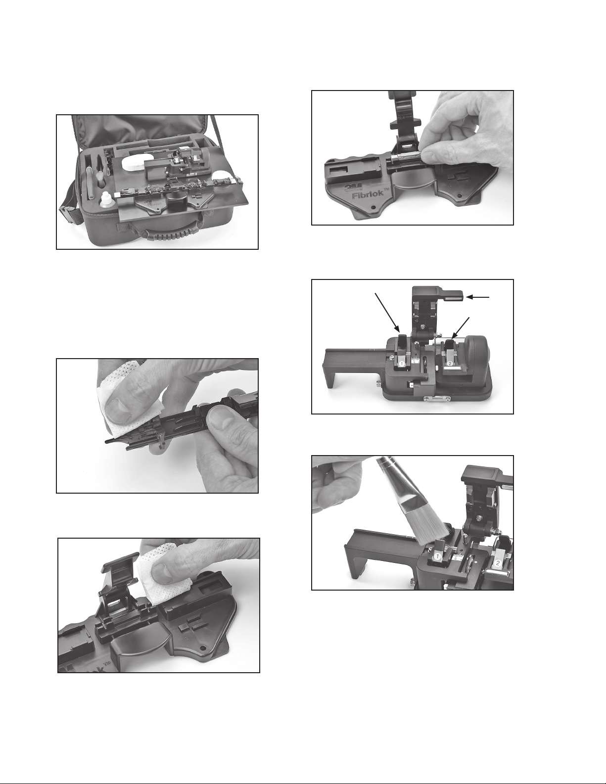
5.8 Hold the cap lifter in place with one hand and push
down on the ends of the splice with the other hand.
This action should reseat the splice into the holding
cradle and lift the cap at the same time.
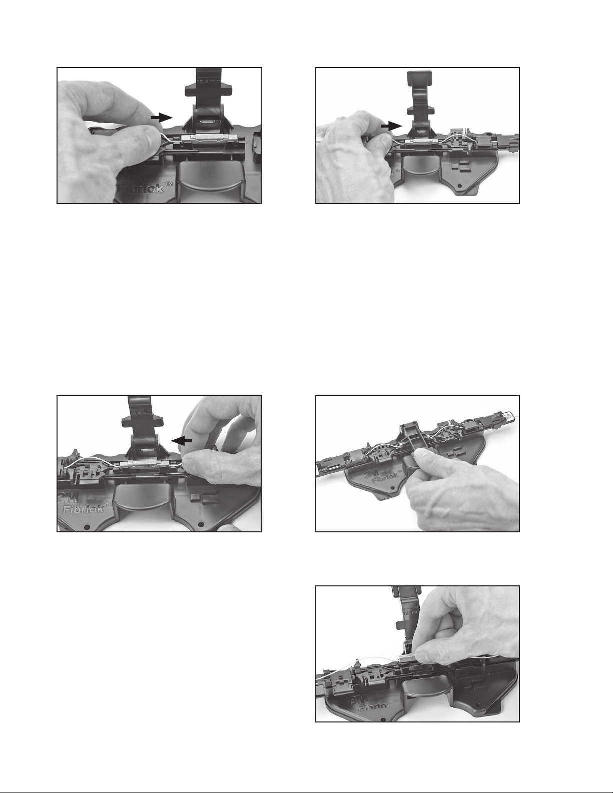
5.5 Repeat fiber centering and splice actuation (See steps
4.6 – 4.8.) Open the fiber holder clamps and remove
splice from tool. If after two attempts an acceptable
splice loss is not obtained, remove fiber, strip, clean
and re-cleave. Resplice using a new splice.
Note: If there is difficulty using the cap lifter, a
second cap lifter is packaged with the 3M™
Fibrlok™Angle Splice Assembly Tool 2501-AS
that can be used to pull the cap up.
6.0 Fiber Organization and
Splice Storage
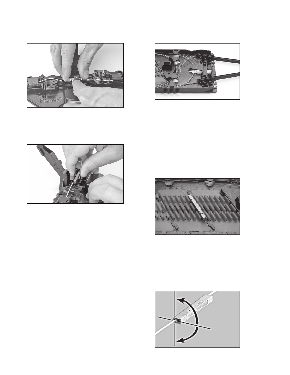
6.1 When storing fiber slack in a splice tray, the spliced
fiber ends will twist one full turn for each full loop
of fiber being stored. This rotation places stress
on the fibers. This rotational stress makes fiber
organization more difficult and may affect fiber/
splice performance, particularly in 900 µm coated
fibers. The stiffness of the 900 µm fiber does not
distribute this stress in the same manner as 250 µm
coated fiber.
Note: The following procedure must be followed
when splicing 900 µm coated fibers and will
improve fiber organization when splicing all
fiber types.
6.2 Secure the buffer tubes of the fibers to be spliced to
the tray so that the fibers are free to rotate through
the point of attachment.
6.3 Select the first two fibers to be spliced and lay them
into the tray. Trim the two fibers to be spliced so they
are the right length for splicing plus approximately
1.75 inches (45 mm) for fiber end preparation.
6.4 Place the splice assembly tool close to or on top of
the splice tray. Match the orientation of the tool to
that of the splice holder or tray whenever possible.
6.5 Remove the minimum amount of fiber required for
fiber preparation and splicing. Remove less than one
loop if possible.
6.6 Prepare fibers and complete splice as described in
Sections 3 and 4.
6.7 Carefully lay the splice on top of the holder without
securing the splice into the holder.
Note: In order to minimize torsion on the fiber,
perform the following:
6.8 For 250 to 250 µm and 900 to 900 µm splices:
a. Store the shorter of the two fibers in the tray.
b. Observe how the splice lays in its relaxed state.
Rotate the splice through the smallest possible
angle to install it in the tray.
c. Store the second fiber.