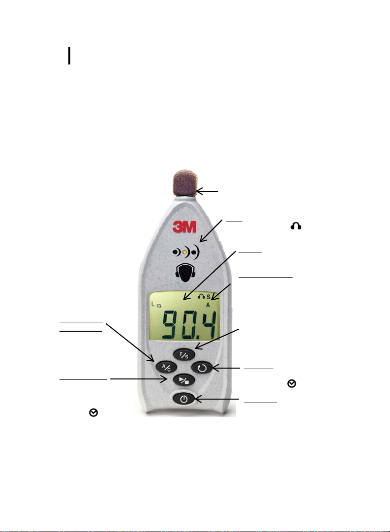
3M SD-200 User manual

3M Occupational Health & Environmental Safety Division
3MTM Sound Detector SD-200
Sound Detector SD-200 User Manual

3MTM Sound Detector SD-200
SD-200: dangers, warnings, cautions & battery
Danger!
Failure to observe the following procedures may result in serious personal
injury
•Not for use in explosive or hazardous locations. This product is not intrinsically safe.
•Containsbuilt-in lithium polymerbattery. Do not incinerate or dispose of in fire. Donot
disassemble, alter, or re-construct.
Warning!
Failure to observe the following procedures could damage the instrument
•Read the manual before operation.
•Do not store in temperaturesexceeding 70°C (158°F).
•Do not immerse in liquids.
•Condensation may damage your instrument.
•Substitution of components may impair the accuracy of the instrument. Repair should be
done byauthorized service personnel only.
Caution!
General
•The batteryin this instrument haslimitedshelf-life, even if never used.
•A non-condensing environment is required for proper measurements.
•Do not charge battery outside the range of 0°C to 40°C (32°F to 104°F).
•Battery run-time may be reduced when operating at lower than 0°C (32°F) temperatures.
Battery power and first use recommendation
It is recommended to fully charge the SD-200 for approximately 12 hours prior to
first use.
Intended Use:
The SD-200 is intended to measure sound pressure levels in air. Consult your
company’s safety professional for local standards, or call 3M at 1-800-243-4630.

i. Table of Contents
Table of Contents
SD-200 Overview.......................................................................................................................................1
Powering on...............................................................................................................................................2
Viewing SoundPressure Level (SPL)..................................................................................................2
Powering off..............................................................................................................................................2
Operating...................................................................................................................................................3
Overview of operation...........................................................................................................................3
Integrating measurements....................................................................................................................3
Running and stopping...........................................................................................................................4
Viewing measurements.........................................................................................................................4
LED alert screen...................................................................................................................................4
Screen indicators..................................................................................................................................6
Settings......................................................................................................................................................7
Frequency weighting and time response..............................................................................................7
Exchange rate (ER)..............................................................................................................................7
Charging.....................................................................................................................................................7
Windscreen................................................................................................................................................8
Positioning and tripod mount..................................................................................................................8
Calibrating .................................................................................................................................................9
Self help .....................................................................................................................................................9
Resetting...............................................................................................................................................9
APPENDIX A: SPECIFICATIONS...................................................................................................10
Standards.................................................................................................................................................10
Mechanicalcharacteristics....................................................................................................................10
Electrical characteristics........................................................................................................................10
Environmental effects ............................................................................................................................11
Temperature Ranges..............................................................................................................................11

ii. Table of Contents and Figuresand Tables
User Interface..........................................................................................................................................11
Display................................................................................................................................................11
Keypad................................................................................................................................................11
Measurements.........................................................................................................................................11
Calibration ...............................................................................................................................................12
Charging...................................................................................................................................................12
Special functions....................................................................................................................................12
Product Information…………………………………………………………………………………………….12
Accessories ............................................................................................................................................12
Updates....................................................................................................................................................12
Warranty...................................................................................................................................................13
Contact/Service information..................................................................................................................13
Figures and Tables
Figure 1-1: SD-200 overview..................................................................................................................1
Figure 1-2: Powered on with SPL screen displayed...........................................................................2
Figure 1-3: Power off screen indication...............................................................................................2
Figure 1-4: Comparison of noise sampled over run-time (SPL & LEQ values).................................3
Figure 1-5: LEQ/LAVG screen....................................................................................................................4
Figure 1-6: LED Alert screen .................................................................................................................5
Figure 1-7: Charging...............................................................................................................................7
Figure 1-8: Windscreen attached..........................................................................................................8
Figure 1-9: Positioning and tripod mount............................................................................................8
Figure 1-10: Calibrating the SD-200........................................................................................................9
Table 1-1: LED alert levels......................................................................................................................5
Table 1-2: Screen indicators...................................................................................................................6

1SD-200 Overview
SD-200 Overview
The SD-200 is intended to provide measurements of sound pressure levels in air.
With five easy-to-use keys, the keypad is used for powering on/off, viewing and/or
running measurements, navigating, and setting parameters. (See Table 1-2 for
more information.)
Note:for typical sound measurements when determining hearing protection,
the SD-200 may be set to “A weighting” with “Slow” response.
Figure 1-1: SD-200 overview
Display
View measurements and screen indicators
Screen indicators
The screen indicators identify
settings and values
On/Off key
Powers the SD-200 On/Off
A/C frequency
weighting key
Press to select
A or C frequency
weighting
Microphone with an attachedwindscreen
Fast/Slow time response key
Press to select fast or slow
time response
Mode key
Cycles through the measurements
and Run-Time screens
Run & Stop key
Runsand stops
integrating
measurementsover the
Run-Time
LEDs
Used in the LED alert measurement screen

2Powering on
Powering on
Press key until the LCD turns on. (Warm-up time isabout 5 seconds.)
Whenpoweredon, a self test screen flashes with country code and revision level (e.g. U1.0)
and exchange rate (e.g.3 LEQ/5 LAVG). Then a measurement screen appears.
Viewing Sound Pressure Level (SPL)
The measurement screen will display thecurrent Sound Pressure Level (SPL) in dB or the
previouslyviewed screenprior to powering off.
Note: no screen indicator appears for SPL.
Figure 1-2: Powered on with SPL screen displayed
Powering off
Once powered off, the SD-200 will save the instrument’ssettings and measurements which
are displayed again when powered back on. The SD-200 will not power off while in run mode.
1. Press and hold key until OFF disappears. Releasing within two seconds will keep
the instrument powered on.
Note: while in run, the instrument will notpower off untilstop is pressed. If the
instrument powers off due to low battery, it will store the last viewed measurements.
(See “Resetting” for more information.)
Figure 1-3: Power off screen indication
On/Off key
To power On/Off,
pressand hold for
about2 seconds
Battery icon
If icon appears,
thisindicatesbattery
is low and requires
charging
Indicator examples
Slow time response and A frequency
weighting indicators
SPL measurements
Value is displayedwith no screen indicator

3Operating
Operating
Overview of operation
The list below is a brief overview of the steps for running a study.
Integrating measurements
Integrating measurementscompute the average value over a period oftime. In many work
environments, noise levels may be highly variable making it difficult to assess the sound level.
With the averaging function, you will see steadier values over the Run-Time (RT).
The chart below depicts the SPL andLEQ values measured over the RT. When the
measurements are compared, the SPL valuesmeasure the maximum and minimum values
while the LEQ provides steadier readings over the length of the study.
Figure 1-4: Comparison of noise sampled over Run-Time (SPL & LEQ values)
Quick Help List: typical sound session
1. Power on the SD-200 and ensure the windscreen is attached.
Note: if battery indicator appears,this signifiesthe instrument needsto be charged.
(See “Charging”)
2. Select the desired settings (A/C weighting,F/S response) and the desired measurementvia
the keypad.
3. Position theSD-200 microphone so it is angled about 70 degreesfrom the noise source.
4. Measures: when first powered on, the SD-200 displaysthe currentSPL orthe lastviewed
parameter prior to power off.
For integrated measurements, press key. (Noting the LEQ/LAVG values will provide
steadier values over a period of time.)
To view measurements, repeatedly press key and the SD-200 willtoggle through
the various screens (SPL, LEQ/LAVG, LED Alert , MAX, MIN, Run-Time .)
5. Power off the instrument.
Integrating example
LEQ providessteadier
values (about 90 dB)
over theRT

4Operating
Running and stopping
The run and stop keys are used to start and stop the Run-Time for integrating
measurements which include: LEQ/LAVG (see Table 1-2 for more information), LED
Alert , MAX, and MIN screens.
1. While powered on, press key. The icon appears.
Note:While in run mode, the settings cannot be changed. (See “Settings” for
more information.)
2. To stop, press key. The icon disappears.
Viewing measurements
The mode key is used to view each measurement screen with its related value.
There are six measurement screens: SPL (no measurement indicator), LEQ/LAVG*,
MAX*, MIN*, LED alert *, and Run-time * screens (*while integrating has
occurred).
Figure 1-5: Measurement screens
Integrating
Run indicator and LEQ displayed
Measurement screen examples
(1) SPL screen (2) LEQ/LAVG (3) LED Alert (4) MAX (5) MIN (6) Run-Time
Mode key
The mode key cycles through the measurements
1 2 3
4 5 6

5Operating
LED alert screen
The LED alert screen displays LEQ/LAVG measurements, a detection icon , and
activated LED indicator levels. This measurement screen provides an alternative
view to detect the average dB levels with visual preset LED noise levels. Please
refer to Table 1-1 for the levels.
Figure 1-6: LED alert screen
Table 1-1: LED alert levels
LED Alert Levels
Green LED
Flashes when measurements are between 80 to 85 dB
Yellow LED
Flashes when measurements are between 85 to 105 dB
Red LED
Flashes when measurementsare above 105dB
Detection icon
appears on
measurement
screen with
activated LEDs

6Operating
Screen indicators
Screen indicatorsare a typeof notification identifying measurementparameters&/or screen icons.
Table 1-2: Screen indicators
Indicators
Explanation
SPL
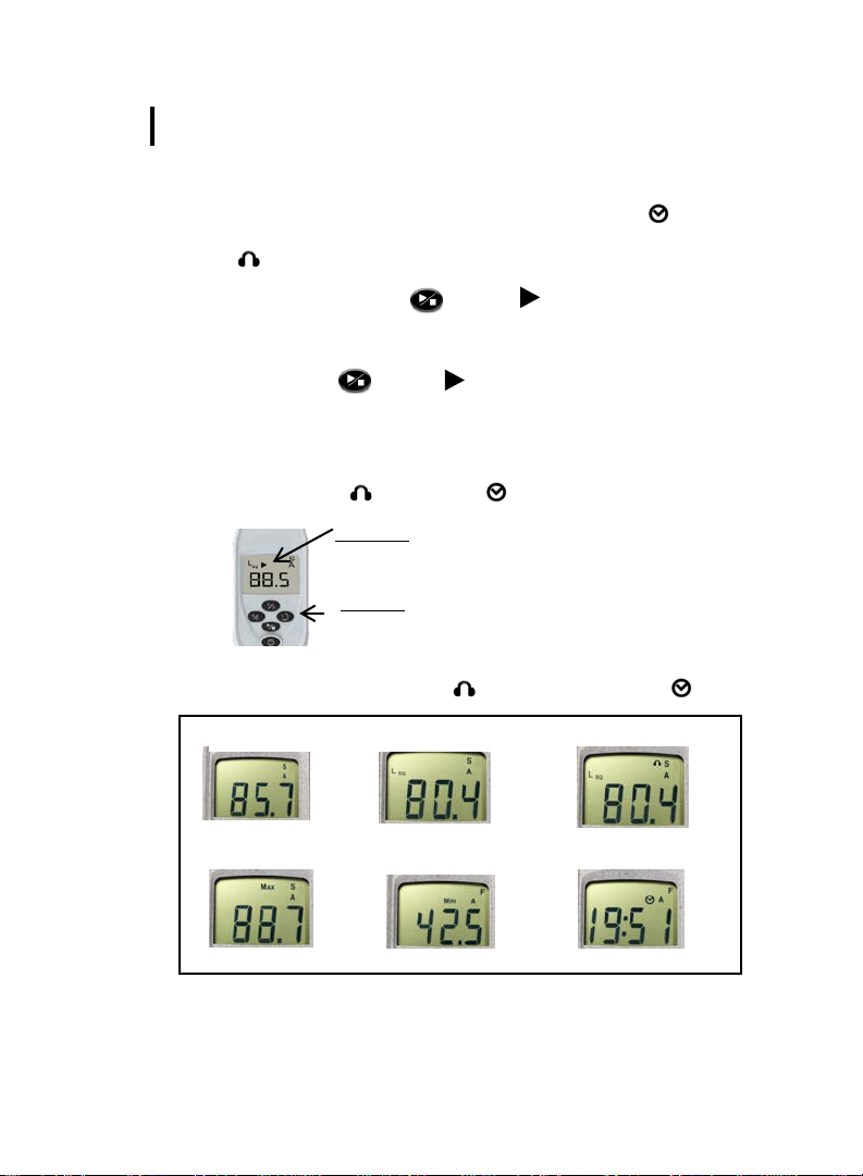
Sound pressure level -The basic measure of noise loudness expressed in decibels. SPL uses
the ratio between a reference level of 20 microPascals (.00002 Pascals) and the level being
measured. It is displayed in decibels (dB).
MAX
Maximum sound level - The highest SPL measured during integrating period.
MIN
Minimum sound level
- The lowest SPL measured during integrating period.
L
EQ/
L
AVG
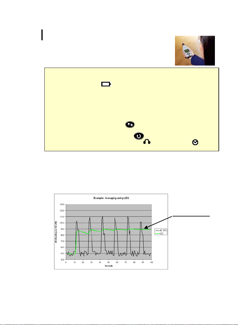
Equivalent pressure sound level/Average sound pressure level – The true equivalent sound
level (or average SPL) measured over the integrating period. The term LEQ is used when 3 dB
exchange rate is applied; The L
AVG
is used when 5 dB exchange rate is applied.
Battery
power
Battery indicator –There are two battery indicator states.
•When battery power icon appears, this indicates the instrument has low power and needs to
be charged.
•Battery power icon flashing indicates the battery is charging.
Run
Run indicator - Signifies that you are measuring L
EQ
/L
AVG
, LED Alert , MAX, and MIN screens
over the Run-Time .
Detection
Detection icon –Appears whenviewing the LED Alert screen. (Note: LEDs will flash if set
points are met or exceeded. See “LED Alert” for more info.
Run-Time
Run-Time – Indicates the time elapsed from the start of the run mode which is used to calculate
the LEQ/LAVG, LED Alert , MAX, and MIN values. Run-Time starts as minutes and seconds
and then changes to hours and minutes when 20 minutes is reached. It will display hours only
after 20 hours.
OL
Overload – Indicates that the dB has exceeded the range of SD-200 (40 -130 dB).
UR
Under Range – Indicates that the displayed measurement is below the linearity range (45 -130
dB).
F/S
Fast/Slow time response - The response time setting determines how quickly the unit responds
to fluctuating noise. Typically, noise is not constant. If you were to try to read the sound level
without a response time, the readings would fluctuate so much that determining the actual level
would be extremely difficult. While the terms slow and fast have very specific meanings (time
constraints), they work very much as you would expect. The fast response would result in a more
fluctuating sound level reading than would the slow response. (See Specifications, “Time
Response”)
A/C
A frequency weighting or C frequency weighting
-
These are frequency filters that approximate
the equal loudness response of human hearing at low, medium, and high SPL’s. A frequency
weighting is the most commonly used filter defined in the international standard IEC 61672:2003.
Common applications of A weighting include industrial noise applications and community noise
regulations (such as: manufacturing noise or machine shop monitoring.) The A frequency weighted
filter makes the sound level meter respond closer to the way the human ear responds to noise at
lower levels. It attenuates the low frequency noise below several hundred Hertz as well as the high
frequency above six thousand Hertz. C frequency weighting is intended to represent how the ear
responds to very high levels.

7Settings
Settings Typical sound level measurements are performed with A frequency weighting, Slow
time response, and the factory default 3 dB exchange rate. If your application
requires other settings, please change accordingly.
Frequency weighting and time response
The frequency weighting and the time response can be changed on the instrument by
pressing the following when in stop mode.
1. To change A or C frequency weighting, press key.
2. To change Fast or Slow time response, press key.
Exchange rate (ER)
The exchange rate can be set to either 3 dB (for LEQ values) or 5 dB (for LAVG
values). The factory default is set at 3 dB. To change, please follow below:
1. While powered off, press and hold key and then press key.
2. The exchange rate screen (with LEQ /LAVG indicators) will appear. Press
key to change the setting.
3. Press key to accept the setting. (To cancel, press key.)
Charging Using the computers USB port, the SD-200 is charged with a mini-USB
cable plugged into the bottom of the instrument. It will charge in 2.5 to 12
hours when the battery is fully discharged based on available power.
Note: when connecting the instrument toyour pc,a new device hardware wizard
will appear. If you cancel the wizard, the instrument will charge without the
drivers. If you wish to install the drivers, they are located at:
www.3M/SoundDetector.com.
Figure 1-7: Charging
SD-200 with USB connector
Battery icon
WhenSD-200 is turned on, it
will flash. When fully charged,
it will no longer flash.
Charging indicator
When turned off, dashes will
appear with the charge icon
flashing.

8Windscreen
Windscreen
The SD-200 features a removable windscreen. This is primarily used to reduce
noise effects from wind with minimal effects on the readings. It is recommended to
use the instrument with the windscreen on at all times in order to protect the
microphone.
When the instrument is shipped, the windscreen will be detached. To attach, slide
the windscreen completely over the microphone.
Figure 1-8: Windscreen attached
Positioning and tripod mount
If hand-held, position the SD-200 microphone angling it at about 70 degrees
from the noise source. To place the instrument in a work zone/area, a tripod
may be used by connecting it to the tripod mount while positioning it at about
a 70 degree angle towards the noise source.
Figure 1-9: Positioning and tripod mount
Windscreen
Tripod mount
Positioning

9Calibrating
Calibrating
A field calibration may be performed before taking measurements to ensure
that your measurements are accurate for the current environment. An
optional calibrator and calibrator adapter are used for this procedure. (See
“Accessories” for more information).
1. While the instrument is off, press and hold key and then press
key. Then release the keys. “CAL” will appear on the screen.
2. Place the calibrator adapter and the calibrator over the microphone, and
then turn the calibrator on.
3. To adjust the level to match the calibrator, press either key to
increase or key to decrease.
4. To accept the level, press key or press key to cancel.
Figure 1-10: Calibrating the SD-200
Self help
Resetting
In theevent your SD-200 locksup for anunknown reason, theSD-200 is equipped with a
reset feature. To reset the instrument, press and hold key for at least 20 seconds and
then release the key. The instrumentwill powerback on.
Note: after a reset, LEQ/LAVG, LEDAlert , MAX, and MIN, measurement screens will
display dashes, “--.-” andRun-Time will display zero, “0:00”.
Please see “Contact/Service information” for additional support.
CAL screen
Calibrator (QC-10)
Calibrator adapter
Accepts
Cancels
Decrease
Increase

10 Standards
Appendix A: Specifications
*All specifications subject to change
Standards
ANSI S1.4 1983 (R 2006)
ANSI S1.43 1997(R 2007)
IEC 61672-1 (2002)
IEC 61010-1 (2010)
CE mark
Mechanical characteristics
Electrical characteristics
Housing
ABS/polycarbonate
Size
(Length x Width x Thickness)
16.5 cm x 6.1 cm x 2.3 cm
6.5” x 2.4” x .9”
Weight
125 g (4.4 oz)
Tripod Mount
Accepts a ¼” – 20 screw (located on bottom,
backside of the instrument).
Battery type
Lithium polymer battery (1000 mAh), rechargeable.
Battery life
3 yr or 500 charge cycles
Battery runtime
•
35 hours with LEDs activated (minimum hours)
(40 hours, typical )
•50+ hours without LEDs activated
Microphone
Frequency range
Omni-directional ; Class/Type 2;
1/2” diameter; electret condenser
31.5 to 8000 Hz

11 Environmental effects
Environmental effects
The typical time intervals needed to stabilize after changes in environmental conditions
include:
•For temperature change of 10 ºC (18 ºF) allow at least 5 minutes.
•For relative humidity change of 30% (non-condensing) allow at least 30 minutes.
•For static pressure change of 10 kPa allow at least 5 seconds.
Temperature Ranges
User Interface
Display
Digit Size: 2 cm ( ¾”)
Resolution: 0.1 dB
Update Rate: 0.5 sec.
Keypad
5 keys: F/S key, A/C key, Mode key, Run/Stop key, Power On/Off key.
Measurements
Displayed data and
status indicators
Sound Pressure Level (SPL), Average value (L
EQ
/L
AVG
),
LED Alert , Maximum value (MAX), Minimum value
(MIN), and Run-Time (max 99 hours), Overload (OL), and
Under-Range (U
R
)
Display Range
Linearity Range
40 to 130 dB (Dynamic range)
45 to 130 dB (Dynamic range)
Frequency Weighting
A or C
Time Response
Fast (125 msec) or Slow (1 sec)
Exchange Rate (ER)
3 dB or 5 dB
Operating temperature:
Operating atmospheric pressure:
32 ⁰F to 104 ⁰F (0 ⁰C to 40 ⁰C)
80 -110kPa
Relative humidity:
0%-90%, non-condensing
Storage temperature:
-4
⁰
F to 158
⁰
F(-20
⁰
C to 70
⁰
C)
Storage atmospheric pressure:
50 -150kPa

12 Calibration
Calibration
Calibrator
Calibrations should be performed at 114 dB at 1kHz.
Charging
Using the computer’s USB port, the SD-200 is charged with a mini-USB cable
plugged into the bottom of the instrument. It will charge in 2.5 to 12 hours when
the battery is fully discharged based on available power.
Special functions
LED’s: light-emitting diodes are activated in the LED alert screen. They will flash at the
following levels:
•Green LED flashes when measurements are between 80 to 85 dB
•Yellow LED flashes when measurements are 85 to 105 dB
•Red LED flashes when measurements are above 105 dB
Product information
•Sound Detector Kit, USB Cable, Windscreen (70-0715-6546-2)
Accessories
•Windscreen (one included ) (3M ID: 70-0716-0639-9)
•Mini-USB cable (one included) (3M ID: 70-0715-8175-8)
•056-990 0.5” Calibrator adapter (3M ID: 70-0715-8115-4)
•Calibrator: QC-10: 114dB at 1 kHz output (3M ID: 70-0715-7972-9)
•Tripod (3M ID: 70-0715-8374-7)
Updates
In the interests of continuous product improvements, 3MTM reserves the right to make
changes to product specifications without notice. To understand the latest updates that
have been implemented into this product and to download the most current version of this
user manual, visit Website: www.3M.com/OccSafety or www.questtechnologies.com.

13 Contact/Service information
Warranty
3M™ Sound Detector SD-200 LIMITED WARRANTY.3M™ warrants the Sound Detector
SD-200 will be free from defective materials and workmanship for one year from date of
purchase (indicated on the sales receipt), provided it is maintained and used in
accordance with 3M instructions and/or recommendations. If any component becomes
defective during the warranty period, it will be replaced or repaired free of charge. This
warranty does not apply to units that have been altered or had repair attempted, or that
have been subjected to abuse, accidental or otherwise. The above warranty is in lieu of
all other express warranties, obligations or liabilities. THE IMPLIED WARRANTIES OF
MERCHANTABILITY AND FITNESS FOR PARTICULAR PURPOSE ARE LIMITED TO
ONE YEAR FROM THE PURCHASE DATE. 3M shall not be liable for any other warranty,
express or implied, arising out of or related to the appropriate use of hearing protection
devices. Manufacturer or its agent’s liability shall be limited to replacement or repair as
set forth above. Buyer’s sole and exclusive remedies are return of the goods and
repayment of the price, or repair and replacement of defective goods or parts.
Contact/Service information
In United States, contact:
Website: www.3M.com/OccSafety
Technical Assistance: 1-800-243-4630
For other 3M products: 1-800-3M HELPS
Or 1-651-737-6501
©2010 3M Company
3M Occupational Health and
Environmental Safety Division
3M Center Building 0235-02-W-70
St. Paul, MN 55144-1000
Printed in U.S.A.
34-8706-1603-3

i3MTM Sound Detector SD-200
SD-200: dangers, avertissements, mises en garde et batterie
3MTM Sound Detector SD-200
SD-200: dangers, avertissements, mises en garde et batterie
Danger!
Si vous ne respectez pas les procédures suivantes, vous risquez de vous
blesser gravement
•Ne pas utiliser dansdes endroits où il existe des risques d'explosionou autresdangers.
L’utilisation de ce produit comporte desdangers.
•Contient une batterie intégrée de polymère au lithium. Ne pas incinérer ou jeterau feu. Ne pas
démonter, altérer ou reconstruire.
Avertissement!
Si vous ne respectez pas les procédures suivantes, vous pourriez
endommager l’instrument
•Lire le manuel avantde vous servirde l’instrument.
•Ne pas ranger à des températures excédant 70 ºC (158 ºF).
•Ne pas immerger dans un liquide.
•La condensation pourraitendommager votre instrument.
•La substitution de composants pourraitnuire à la précision de l’instrument. Les réparations
doivent être faites uniquement par un personnel autorisé.
Attention!
Général
•La batterie de cet instrument a une duréede vie limitée, même si elle n’est jamais utilisée.
•Un environnement sans condensation estnécessaire pour des mesures correctes.
•Ne pas charger la batterie au-delàde la plage de 0 °C à 40 °C (32 °F à 104°F).
•La durée de fonctionnementde la batterie peut être réduite lorsque utilisé àdes
températures inférieuresà 0 º (32 ºF).
Charge de la batterie et recommandation pour la première utilisation
•Il est recommandé de charger à fond le SD-200pendantenviron 12 heures avant de l’utiliser
pour la première fois.
Utilisation prévue
•Le SD-200 est conçu pour mesurer les niveaux de pression du bruit dans l’air.
Consulter le professionnel de la sécurité de votre société pour les normes locales,
ou appeler 3M au 1-800-243-4630.

ii Tabledes matières
Table des matières
Vue d’ensemble du SD-200.....................................................................................................................1
Mettre sous tension.....................................................................................................................................2
Afficher le niveau de pression sonore (SPL)...........................................................................................2
Mettre hors tension......................................................................................................................................2
Mode d’emploi..............................................................................................................................................3
Vue d’ensemble du mode d’emploi.........................................................................................................3
Intégrer les mesures....................................................................................................................................3
Exécution et arrêt.....................................................................................................................................4
Mesuresd’affichage.................................................................................................................................4
Exemples d’écrans de mesure..........................................................................................................4
Écrand’alerte DEL...................................................................................................................................5
Réglages.......................................................................................................................................................7
Pondération de fréquence et tempsde réponse.....................................................................................7
Facteur de bissection (ER)......................................................................................................................7
Recharger......................................................................................................................................................7
Pare-vent.......................................................................................................................................................8
Positionnement et montage sur trépied....................................................................................................8
Étalonnage....................................................................................................................................................9
Autoassistance.............................................................................................................................................9
Rétablissement........................................................................................................................................9
Annexe A : Spécifications........................................................................................................................10
Normes........................................................................................................................................................10
Fonctions mécaniques..............................................................................................................................10
Fonctions électriques................................................................................................................................10
Effets sur l’environnement........................................................................................................................11
Plages de température ..............................................................................................................................11

iii Tabledes matières
Table des matières
Interface utilisateur....................................................................................................................................11
Affichage................................................................................................................................................11
Clavier....................................................................................................................................................11
Mesures.......................................................................................................................................................11
Étalonnage..................................................................................................................................................12
Rechargement............................................................................................................................................12
Fonctions spéciales...................................................................................................................................12
Accessoires (inclus)..................................................................................................................................12
Accessoires (optionnel)............................................................................................................................12
Mises à jour................................................................................................................................................12
Other manuals for SD-200
2
Table of contents
Languages:
Other 3M Measuring Instrument manuals
Popular Measuring Instrument manuals by other brands

Gigahertz Solutions
Gigahertz Solutions HF59B manual

DH Instruments
DH Instruments PG7000 - V2.03 Operation and maintenance manual

Tobii Pro
Tobii Pro Pro Fusion Product description

Pelstar
Pelstar Health o meter Professional ADULTHR User instructions

Shodex
Shodex OHpak SB-2000 Series Operation manual

ABB
ABB AnalyzeIT ZMT Series Supplementary operating instructions