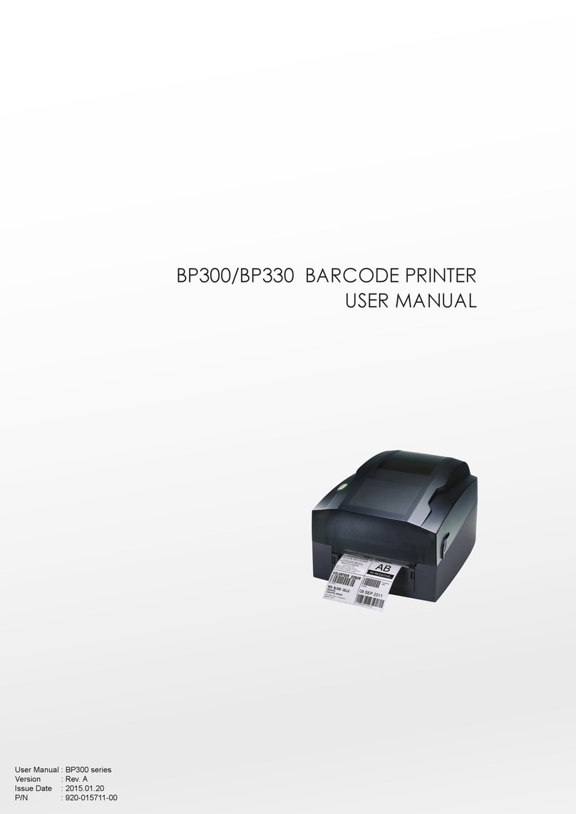
3nStar 2054K Series User manual

1
XP-DT325B
2054K Series
Thermal Barcode Printer
User’s Manual
Direct Thermal Printer
Please keep the user’s manual properly for reference

Contents
Copyright statement.............................................................................................................1
Cautions............................................................................................................................... 1
I. Product............................................................................................................................. 2
II. Receiving........................................................................................................................ 3
2.1 Unpacking and checking accessories.................................................................. 4
2.2 Printer components.............................................................................................. 5
2.2.1 Front view.....................................................................................................5
2.2.2 Rear view......................................................................................................5
III. Installation..................................................................................................................... 6
3.1 Install the printer.....................................................................................................6
3.2 Install the label........................................................................................................7
3.3 Install the stripping module – optional................................................................... 8
3.4 Stripping mode – optional...................................................................................... 9
3.5 Install the cutter – optional................................................................................... 10
IV. LED indicator and button functions.............................................................................10
4.1 LED indicator....................................................................................................... 11
4.2 General button functions.......................................................................................11
4.3 Boot function........................................................................................................ 11
V. Diagnostic Tool............................................................................................................. 16
5.1 Enable the Diagnostic Tool program.................................................................... 17
5.2 Printer settings...................................................................................................... 17
5.3 Calibrate the paper sensor with the Diagnostic Tool............................................ 18
5.4
Set the Ethernet with the Diagnostic Tool (optional)............................................19
VI. Troubleshooting...........................................................................................................21
6.1 Common problems............................................................................................... 21
VII. Simple maintenance procedures of the printer...........................................................25
Update history............................................................................................................26

1
Copyright statement
The manual is provided to the purchaser for reference in use and operation of the
purchased equipment, and shall not be used or copied for other purposes without express
written permission. All other brand names, product names, or trademarks are the property
of other individual owners. Due to continuous product improvement, the machine
specifications, accessories, parts, designs and software contents described in the manual
are for reference only, and subject to the product purchased. Changes may be made
without prior notice.XP does its best to ensure that the contents of the manual are correct,
but errors are still likely to occur. XP reserves the right to correct any such errors and
declares that it shall not be liable for any consequences caused thereby.
Cautions
1. When opening the cover of the printer, keep fingers and other parts of

2
your body away from the paper exit to avoid crushing injury.
2. If the button battery RTC contained in the main board is not replaced
correctly, the main board cannot be used normally.
3. Please dispose of the used batteries according to the manufacturer’s
operation instructions.
I. Product
Thank you for purchasing our 2054K series thermal barcode printer. This desktop printer
will provide you with safe, reliable and efficient printing at a reasonable price. By using it,

3
the volume labels can be printed in a wide range of texts or graphic formats. Meanwhile, its
superior function and easy operation make it your best choice among the thermal barcode
printers of the same level.
The 2054K series printer provides thermal printing. The printing speed is adjustable
from 2.0, 3.0, 4.0, 5.0 to 6.0 inches per second. It applies to a variety of printing materials,
including paper rolls, paper slices and fan-fold labels. In addition, the printer has the
built-in 1D and 2D barcodes that are commonly used, a TTF font and eight sets of English
numeric fonts in different sizes, and supports printing in 4 different directions. And through
the zoom function, the fonts can be enlarged. All these will enable you to improve the label
printing efficiency significantly.
II. Receiving
This printer is specially packaged to protect against possible damage in transit.
However, since the printer may still be subjected to unexpected damage during

4
transportation, you are kindly required to check the packaging and all units carefully when
receiving the printer. In case of obvious damage, please contact the sales dealer directly and
indicate the severity of the damage. If necessary, you should keep the packaging materials
for returning the printer.
2.1 Unpacking and checking accessories
Once you have received your barcode printer, place it on a clean, steady table and
carefully remove the packaging materials. Check if the following items are included:
One printer
One disk
Paper supply kit (1" core)
One USB cable
One power supply
One power cord
One copy of quick installation guide
Dealer's options:
Peel-off module (factory optional)
Ethernet interface (factory optional)
WIFI interface(factory optional)
Bluetooth interface(factory optional)
RTC battery (factory optional)
Cutter module (factory optional)
User’s options:
External paper roll holder (O.D. 214 mm with 1" or 3" core)
Bushing of paper roll shaft: 1.5", two

5
2.2 Printer components
2.2.1 Front view
2.2.2 Rear view
1.
Power switch
2.
Power socket
3. USB interface
4. Ethernet interface
5. SD card slot
Note: The transmission interfaces of the printer in the picture will vary depending on the
model of machine you purchase. For the actual transmission interface, please refer to the
catalog specifications.
Cover hook
Feed button
Front panel
Paper exit
Power indicator
Transparent window
Printer cover
1 2 3 4 5

6
III. Installation
3.1 Install the printer
1. Place the printer on a smooth and steady surface and
make sure the power is off.
2. Plug one end of the parallel port cable, serial port
cable or USB cable into the slot on the back of the
printer, and connect the other end of the cable to the
appropriate slot of your computer.
3. Plug the power cord into the power slot on the back
of the printer and plug the other end into an AC socket.
Note: Make sure the printer power is switched off when
you plug the power cord into the power slot on the back
of the printer.

7
3.2 Install the label
1. Install the label into the paper supply kit. (Fixing plate & Paper roll shaft )
*1.5"纸卷轴榇套
纸卷
打印面朝上
纸卷轴
固定片
2. Push the printer cover hook forward with both hands to open the printer cover.
3. Place the label roll on the label roll holder. (Print side up)
4. Pass the label through the paper guide and pull the label over the rubber roller.
Fixing plate
Print side up
1" Paper roll shaft
Paper roll
Fixing plate
Print head
Label holder
Paper guide
Printer cover hook
Rubber roller

8
5. Close the printer cover.
Note: To avoid poor printing quality, make sure the printer cover is closed tightly.
3.3 Install the peel-off module – optional
1. Push the cover hook forward with both hands to open the upper cover of the printer.
2. Dismantle the front panel, insert the peel off cable into the corresponding socket hole.
3. Install the peel-off module into the lower inner cover groove.
4. Gently push the stripping panel to lock the lower inner cover.
5. Reinstall the upper cover on the printer.

9
3.4 Install the label with peel-off module
1. Pull the paper stripper apart.
2. Pass the label through the paper guide, and pull the label over the rubber roller.
3. Pass the label through the backing paper exit under the roller (as shown by the blue
dotted line below).
4. Adjust the center offset label guide with your finger to adapt to the edge on the back of
the label.
Peel-off roller
front panel

10
5. Close the front panel.
6. Put on the upper cover of the printer.
3.5 Install the cutter – optional
1. Push the cover release button forward with both hands to open the upper cover of the
printer.
2. Insert the cutter cable into the corresponding socket hole.
3. Align the cutter module with the lower inner cover groove.
4. Gently push the cutter module downward to lock the lower inner cover.
5. Reinstall the upper cover on the printer.
IV. LED indicator and button functions
This printer has one button and one indicator that can display three colors. Pressing the button in

11
conjunction with different colors or collaborating with the power switch will enable the printer to
start multiple functions, such as feeding paper, pausing the printer, calibrating the label sensor,
printing the self-test value, and initializing the printer. Details are described as follows:
4.1 LED indicator
LED indicator color
Description
Blue (fixed)
Power on, printer standby to print.
Blue (blinking)
The printer is downloading data or the printer is paused.
Purple
The printer is formatting the data.
Red (fixed)
Printer is in head opened or cutter error status.
Red (blinking)
Printing error occurs, e.g. out of paper, paper jam, or memory
error, etc.
4.2 General button functions
1. Paper feeding
When the printer is standby (LED blue fixed), the installed paper will move forward one unit
if feed button is pressed once.
2. Pausing of printing operation
While the printer is printing, Press the feed button will pause the operation. At this point,
the power indicator blinks blue. Press the button again to resume the printing.
4.3 Boot function
This printer has four boot functions that can be used to set or test the printer's hardware.
Please follow the steps below to start the boot function:
1. Turn off the printer.
2. Turn on the printer while holding down the button.
3. Release the button with the light signal indicating the required function, as listed in the table
below.
Boot function
Indicator color cycle mode:
Indicator signal
Function
Purple
Blue
Red
Purple
Blue
Blue
(Blink 5 times)
(Blink 5 times)
(Blink 5 times)
(Fixed blue)
1. Gap/black mark sensor detection
Release the button
2. Gap/black mark sensor detection,
printing self-test value and entering the
debugging mode
Release the button
3. Printer initialization (restore factory
defaults)
Release the button
4. Skip the AUTO.BAS program
Release the button
4.3.1 Gap/black mark sensor detection
This test aims to determine the sensitivity of the label paper sensor after the printer is turned on.
When the user installs a new paper roll of a different specification or initializes the printer and

12
restores it to the factory default value, the label paper gap sensor needs to be re-measured. The
gap detection or black line mark calibration will be completed with your last set value as the
reference value. The default value of this printer sensor is set to gap calibration.
Please follow the steps below to calibrate the ribbon and gap/black mark sensor:
1. Turn off the printer.
2. Turn on the printer while holding down the feed button.
3. When the indicator blinks red after the first purple, release the feed button.
Indicator color cycle mode:
Purple
Blue
Red (blink 5 times)
Purple (blink 5 times)
Blue (blink 5 times)
Blue (fixed)
Note:
Whether the printer volume label sensor detects the gap or the black mark depends on the GAP or
BLINE command sent to the printer (with your last set value as the reference value, the default
value of the printer sensor is set to gap calibration); for more information on GAP and BLINE
commands, please refer to the TSPL2 programming manual.
4.3.2 Gap/black mark sensor detection; printing self-test value and entering the
debugging mode
This test aims to determine the sensitivity of the label paper sensor after the printer is turned on.
When the user installs a new paper roll of a different specification or initializes the printer and
restores it to the factory default value, the label paper gap sensor needs to be re-measured. The
gap detection or black line mark calibration will be completed with your last set value as the
reference value. The default value of this printer sensor is set to gap calibration.
Please follow the steps below to calibrate the label paper by the sensor:
1.Make sure that the label paper is properly installed
2.Turn off the printer
3.Turn on the printer while holding down the feed button
4.When the indicator blinks purple after the first purple, release the feed button
Indicator color cycle mode:
Purple
Blue
Red (blink 5 times)
Purple (blink 5 times)
Blue (blink 5 times)
Blue (fixed)
5.The sensor will calibrate the label paper and the printer will print out the self-test value, and
finally enter the debugging mode and print out the value
6.Turn the machine off and on again to return the printer to the normal printing mode
Note:
Before carrying out the label paper sensor calibration, first confirm the type of label to be detected
with Diagnostic Tool or GAP/BLINE command. For more information on GAP and BLINE
commands, please refer to the TSPL2 programming manual.
Self-test
When the sensor calibration is completed, the printer prints out the self-test value. Before
connecting the printer to your computer, you can use self-test to confirm that the printer is
functioning properly. The self-test info can be used to check the printing quality of the print head

13
and know the internal settings of the printer.
Internal settings of printer printed in the self-test mode
Model & firmware version
Machine serial number
Print head mileage
Check code
Serial port setting
Character set
Country code
Printing speed
Printing density
Paper size (width, height)
Black mark or gap size (vertical gap,
offset)
Sensor strength
Debug mode
After the self-test is printed, the printer system enters the debugging mode. In the debugging
mode, all the volume labels will be printed as machine code. The ASCII strings on the left are
the data received by the system. The data on the right are printed from the strings on the left, in
hexadecimal values. This function is provided for users or engineers to debug programs. You
only need to restart the printer to leave the debugging mode and return to the normal printing
mode.
Stored file information
Print head check sample

14
Note:
1. Label paper of 4" wide is required to print all the debugging mode data.
2. Restart the printer to leave the debugging mode and return to the normal printing mode,
or press the FEED button to return to the standby state.
4.3.3 Printer initialization
The printer initialization function is to clear the downloaded files in the memory (DRAM) and
restore the print parameters to the factory default settings.
ASCII string
Hexadecimal value
data corresponding to
the ASCII string listed
on the left

15
Please follow the steps below to complete the initialization:
1. Turn off the power.
2. Hold down the feed button and turn on the power. At this point, the power indicator color
will cycle as follows:
Indicator color cycle mode:
Purple
Blue
Red (blink 5 times)
Purple (blink 5 times)
Blue (blink 5 times)
Blue (fixed)
3. Release the feed button when the power indicator is blinking blue. At this point, the printer
will be reset, and then the power indicator will blink purple once, and finally the power
indicator will be blue in ready state.
After initialization, the printer configuration is restored to its default values as follows:
Parameters
Defaults
Speed
152.0 mm/sec (6 ips) (203DPI)
Density
8
Label width
4” (100 mm)
Label height
7.9” (180 mm)
Sensor type
Gap sensor
Gap setting
0.16” (4.0 mm)
Printing direction
0
Reference point
0,0 (upper left corner)
Offset
0
Tear-off mode
On
Peel-off mode
Off
Characters
850
Country code
001
Clear flash
No
IP address
DHCP
4.3.4 Skip the AUTO.BAS program
The TSPL2 command language allows the user to load an auto-execute file (AUTO.BAS) into
the flash memory. When the printer is turned on, it will be automatically executed according to
the file loaded by the user. When you want to skip the AUTO.BAS after power-on, you can use
this boot function to ignore this auto-execute file.

16
Please follow the steps below to skip AUTO.BAS:
1. Turn off the power.
2. Hold down the feed button and turn on the power. At this point, the power indicator color
will cycle as follows:
Indicator color cycle mode:
Purple
Blue
Red (blink 5 times)
Purple (blink 5 times)
Blue (blink 5 times)
Blue (fixed)
3. Release the FEED button when the indicator is fixed blue.
4. The printer will skip the AUTO.BAS program.
V. Diagnostic Tool
Diagnostic Tool is an easy-to-use window-type utility program that allows you to check the current
status and settings of the printer, download graphic files, programs, font files, etc., and complete
firmware updates according to the actual need. Moreover, it supports creation and download of
dot-matrix fonts, transmission of commands or files and so on. By using it, you can complete the
printer setup, check the printer status and troubleshoot the printer usage problems more easily.

17
5.1 Enable the Diagnostic Tool program
1. Move the mouse cursor to the Diagnostic Tool image and double click the
left mouse button.
2. After it is started, the main screen shows 4 management pages (printer settings, file
management, communication tools, system printer settings).
5.2 Printer settings
1. Select the connection interface between your computer and the printer.

18
The default communication interface of
the Diagnostic Tool program is USB, so if
the computer is connected through USB
cable for transmission, no changes need to
be made to the settings.
2. Click on a function you intend to set in the "Printer Settings".
3. The printer functions in the Printer Settings management page are described as below:
Description
Sensor Calibration
Set Ethernet Network
Set Printer RTC Time Parameters
Restore Factory Defaults and Reboot
Restart the Printer
Print Test Page
Print Self-test Page
Enter Printer Debugging Mode
Ignore the AUTO.BAS File
Set the Diagnostic Tool Password
5.3 Calibrate the paper sensor with the Diagnostic Tool
5.3.1 Automatic correction
1. Make sure that the paper is installed correctly and the print head is closed.
2. Turn on the printer.
3. Start the Diagnostic Tool and set the transmission interface (the default is USB).
The default communication interface of
the Diagnostic Tool program is USB, so if
the computer is connected through USB
cable for transmission, no changes need to
be made to the settings.
4. Click on "Sensor Calibration".
5. Select the paper type and click on "Calibration". The printer will automatically feed the paper
to calibrate the sensor.
This manual suits for next models
1
Table of contents
Other 3nStar Barcode Reader manuals

3nStar
3nStar SC365 User manual

3nStar
3nStar PTE0905-MSR User manual

3nStar
3nStar SC430 User manual

3nStar
3nStar SC455 Owner's manual

3nStar
3nStar SCI150 User manual

3nStar
3nStar SC050 User manual

3nStar
3nStar SC505 User manual

3nStar
3nStar SC430 User guide

3nStar
3nStar SC050 Owner's manual

3nStar
3nStar SC550 User manual