6241 Mainboard Chapter 1 Introduction
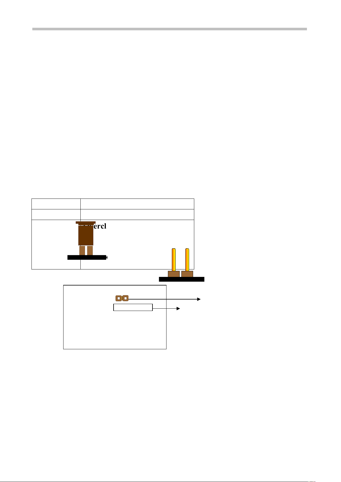
1-7 Keyboard & PS/2 Mo se Power On (JP9)
With ATX Power Supply and Jumper 9 set to Pin 1-2 closed, 6241 Mainboard is
enabled to Keyboard & PS/2 Mouse Power On functions :
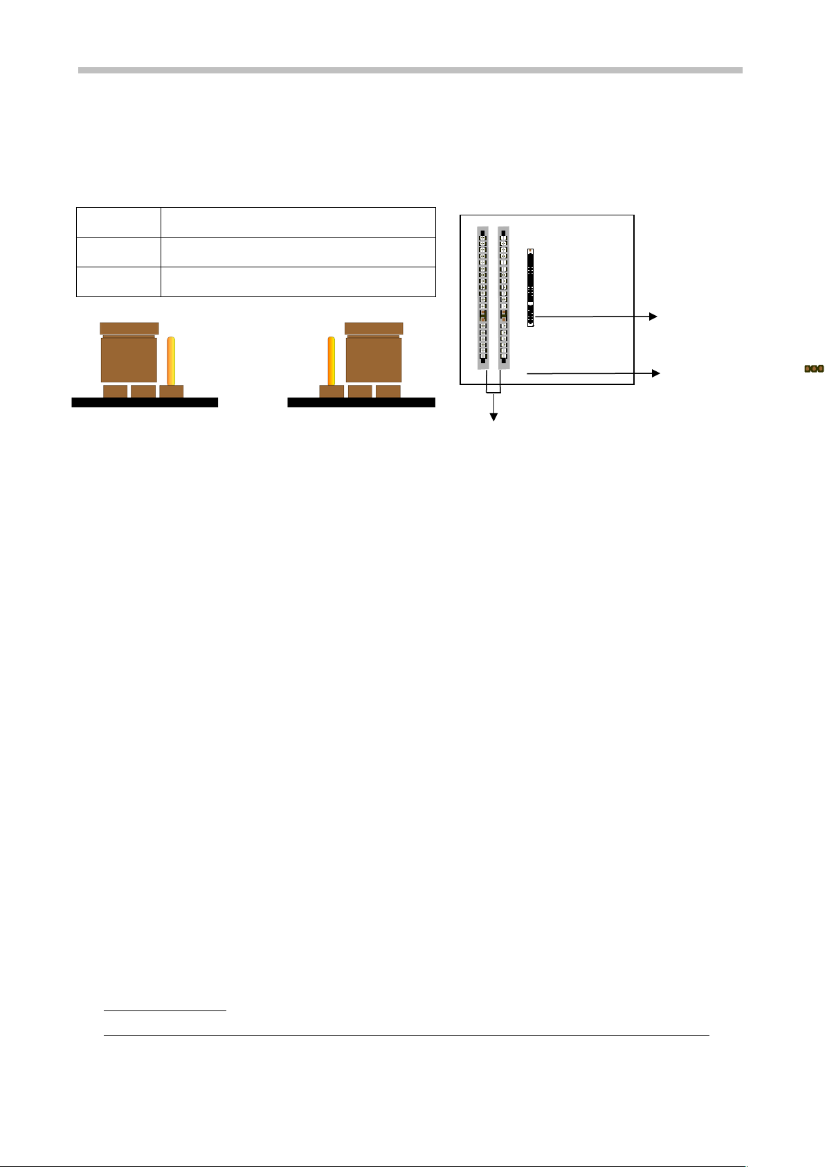
JP 9 KB & PS/2 Mo se Wake p
1-2 Enable
2-3 Disable
(a) Enable (b) Disable
The default Power On function is “Button Only”. That means, we can only turn our
computer on and off by pressing the “Power Button”. If we want to enable KB & PS/2
Mouse Power On function, we first have to set JP9 to Pin 1-2 closed, and then go to
“Power On Function” in “Integrated Peripherals” of Award BIOS Setup. At the line
“Power On Function”, we can press “Page Up” or Page Down” to make the following
selections:
1. Password(via Keyboard):
When user selects “Password”, it will show “Enter Password:”. After user has
typed the password, screen will show “ Confirm Password:” and user has to type
the same password to confirm it. Save selection and shut down system. Now
computer will only be powered on by entering correct password.
In case the set password is forgotten, carry out “Clear CMOS” (Page 14) to clear
password, or computer can not be powered on.
2. Hot Key (via Keyboard):
When user selects this option, screen will show another line : “Hot Key Power ON :
Ctrl-F1”. User can select from “Ctrl-F1” to “Ctrl-F12” as Hot Key by pressing
PageUp / PageDown. After fixing Hot Key, save selection and shut down system.
Now computer will only be powered on by pressing the correct Hot Key.
3. Mo se Left, Mo se Right (via PS/2 Mo se):
This function is available via PS/2 mouse only. User can select either “Mouse Left”
or “Mouse Right” from the “Power On Function” line. After picking either option,
save selection and shut down system. Now computer will only be powered on by
double-clicking the correct PS/2 Mouse button.
Do not slide the mo se when yo click; or yo can’t power on the system.
4. B tton Only (via Power B tton): “Button Only” is default setting, at which