A-Trend Atc-6240m Mounting instructions

6240M Mainboard Contents
1
CONTENTS
COMPONENT LOCATION DIAGRAM…………………..……A
CHECK LIST OF THE PACKAGING…………..………..……..B
CONNECTORS AND JUMPERS DESCRIPTION ..…..……….C
TABLE OF CONTENTS……………………………………….…...1
HOW TO USE THIS MANUAL……………….……………...…...2
CHAPTER 1 Introduction……………………….…….…….……3
1-1 System
Features…………………………………..……………..…...…..3
1-2 Software Power Off Control……………………………..……..…....…..
4
1-3Fan Off Control……………………………………………….…..….…..
4
1-4 Running 100MHz CPU Bus(Jp11) ……………………………...…..…..5
1-5 SB-Link Sideband Signals (JP6)………………………………..…...…..6
1-6 Modem Ring On………………………………………………...….……
6
1-7 Keyboard & PS/2 Mouse Power On (JP9)…………………….…..….....
7
1-8 Wake-On-LAN ……………………………………………….…...……
.8
1-9 Thermister (Option) …………………………………………….....……8
1-10 LDCM (LANDesk Client Manager, option) …………..………….…...9
CHAPTER 2 Installation………………….………………...…...10
2-1 Installation Proceddure…………………………………………………10
2-2 CPU Installation………………………………………………....……..10
2-2-1 Core/Bus Freq.Ratio…………………………………………...….....10
2-2-2CPU Setting………………………………………………….…...…..11
2-3 System Memory Installation…………………………….…………......12
2-4 IDE Driver Installation……………………………………….…..……13
CHAPTER 3 Award BIOS Setup……………...………….….…15
3-1 Update BIOS Procedure…………………………………………..……16
3-1-1 Update microcode API…….………..………..…….....……17
3-2 Award System BIOS Configuration Setup…………………...18
Appendix A How to Install PentiumIII、PentiumII、Celeronand
Processors with SECC2 Package
Appendix B How to Setup Thermister
Appendix C Technical Support Request Form

How To Use This Manual 6240M Mainboard
2
HOW TO USE THIS MANUAL
This manual is written in a user-friendly style. It would be advisable for
users to read it in an orderly sequence :
1. For Hardware Information:
Read Page A: COMPONENT LOCATION DIAGRAM,Page B: CHECK LIST OF
THE PACKAGING and Page C: CONNECTORS AND JUMPERS DESCRIPTION.
2. For Mainboard and System Features:
Read “Chapter 1 Introduction” in detail, and you will find helpful information on
mainboard and system features. Especially, when you want to do some feature
setup, detailed instructions are provided therein to help you through.
3. For CPU, Memory and Drivers Installation:
Read “Chapter 2 Installation” for your CPU, memory and application drivers
installation. Detailed instructions are provided to guide all kinds of users.
4. For BIOS Update and Setup:
Read “Chapter 3 Award BIOS Setup” for updating your mainboard BIOS and
setting up your BIOS Configuration.
5. For Installing Pentium II/III, Celeron or Processors with SECC2 Package:
Read APPENDIX Afor setting up Intel Pentium
III, Pentium
II, CeleronTM, or
processors with SECC2 package.
6. For Installing Thermister:
Read APPENDIX B for thermister installation. You will find that the
self-explanatory drawings enclosed therein make the job easy and simple..
7. For other Technical Support:
Read APPENDIX C , fill and send the Request Form to your dealer for other
technical support.
Since the default setting on a mainboard is not always what a user expects to be.
A user-friendly manual would be the handiest assistant to help change the
on-board configuration or default setting. In case this manual cannot solve all
your problems, please ask your dealer for help and be sure the warranty on
your system is still valid.
REMARK: Intel®is a registered trademark of Intel Corporation.
All other brands and product names are registered trademarks of their respective companies.

6240M Mainboard Chapter 1 Introduction
3
CHAPTER 1 INTRODUCTION
Welcome to use 6240M mainboard. It utilizes the latest Intel 440BX chipset to
support both 66MHz and 100MHz Front Side Bus Intel CPUs. It also provides
up to 4 DIMM sockets for memory expansion. This high performance design
will satisfy needs of various customers.
1-16240M System Features
:CPU Slot supporting Intel Pentium
III CPU 450Mhz to 500MHz,
Pentium
II CPU 233MHz to 450MHz and Intel Celeron
CPU 266MHz to
466MHz.
:Intel 440BX AGP set.
:Four 168-pin DIMM Sockets in four banks of 64-bit wide path up to 512MB
SDRAM or 1GB registered SDRAM (with parity chip ECC support).
:Built-in Switching Voltage Regulator.
:Auto-detect CPU Core Voltage Range from 1.3V to 3.5V.
:One AGP Slot, four PCI Slots with revision 2.1 interface compliance and
two 16-bit ISA Slots.
:Dual Master IDE Connectors supporting Ultra DMA/33(33MB/sec), up to
four devices in two channels for connecting high capacity hard disk,
CD-ROM, LS-120MB floppy drive, tape backup etc.
:Winbond 83977 high-speed Ultra Multi-I/O Chipset.
:ATX Power Connector.
:USB (Universal Serial Bus) Connector up to 127 peripheral devices.
:PS/2 Keyboard Connector and PS/2 Mouse Connector.
:Infrared Transfer (IrDA TX/RX) Connection.
:One FDD Port supporting two devices up to 2.88MB.
:Two 16550A fast UARTs compatible Serial Ports.
:One EPP/ECP Mode Parallel Printer Port.
:Software Power Off Control; Modem Ring On; SB-Link; Keyboard & PS/2
Power On; Wake-On-LAN Functions.
:Built-in Hardware Health Monitor Chip. (optional)
:Intel LDCM Software. (optional)
:ATX Form Factor; Board Dimension 305mm x 190mm. (12" x 7.48")

Chapter 1 Introduction 6240M Mainboard
4
1-2 Software Power Off Control
6240M Mainboard supports Software Power Off Control feature through
the SMM code in the BIOS under Windows 95/98, and MS-DOS operation
system environment. This is Intel ATX form factor feature and you should use
ATX power supply.
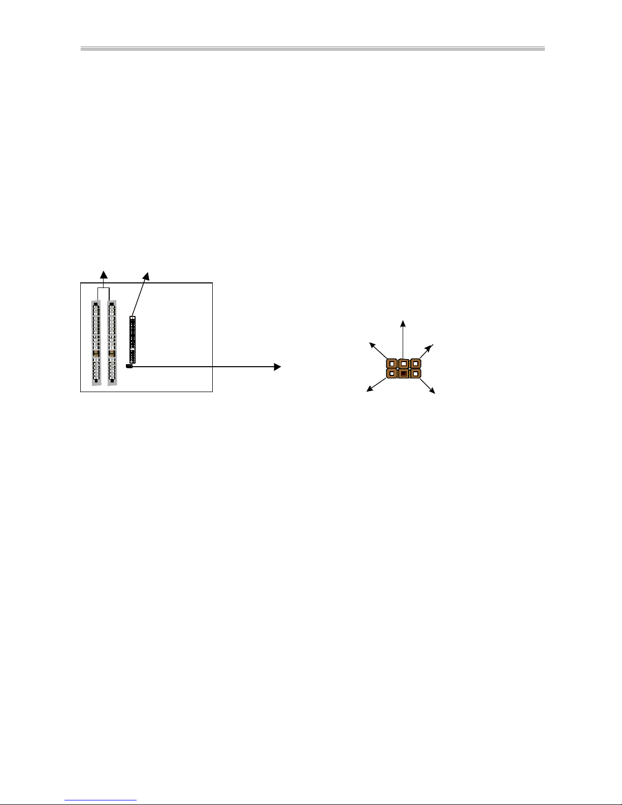
First, you should connect the power switch cable to the connector
“PS-ON” on the mainboard. In the BIOS screen of POWER MANAGEMENT
SETUP’, choose “User Defined” (or “Min. Power Saving” or “Max. Power
Saving”) in ‘Power Manager’ and pick up “Yes” in ‘PM Control by APM’.
In Windows 95/98, to power off the system, you just need to choose
“shutdown the computer ?” in the “Shut Down Windows“ from Windows 95/98.
Then the system power will be off directly, and stay at the stand-by status. If
you would like to restart the system, just press the power switch button, and the
system will be powered on.
Note : If you are going to leave your system idle for several days, we suggest you use
hardware power off to shutdown your system.
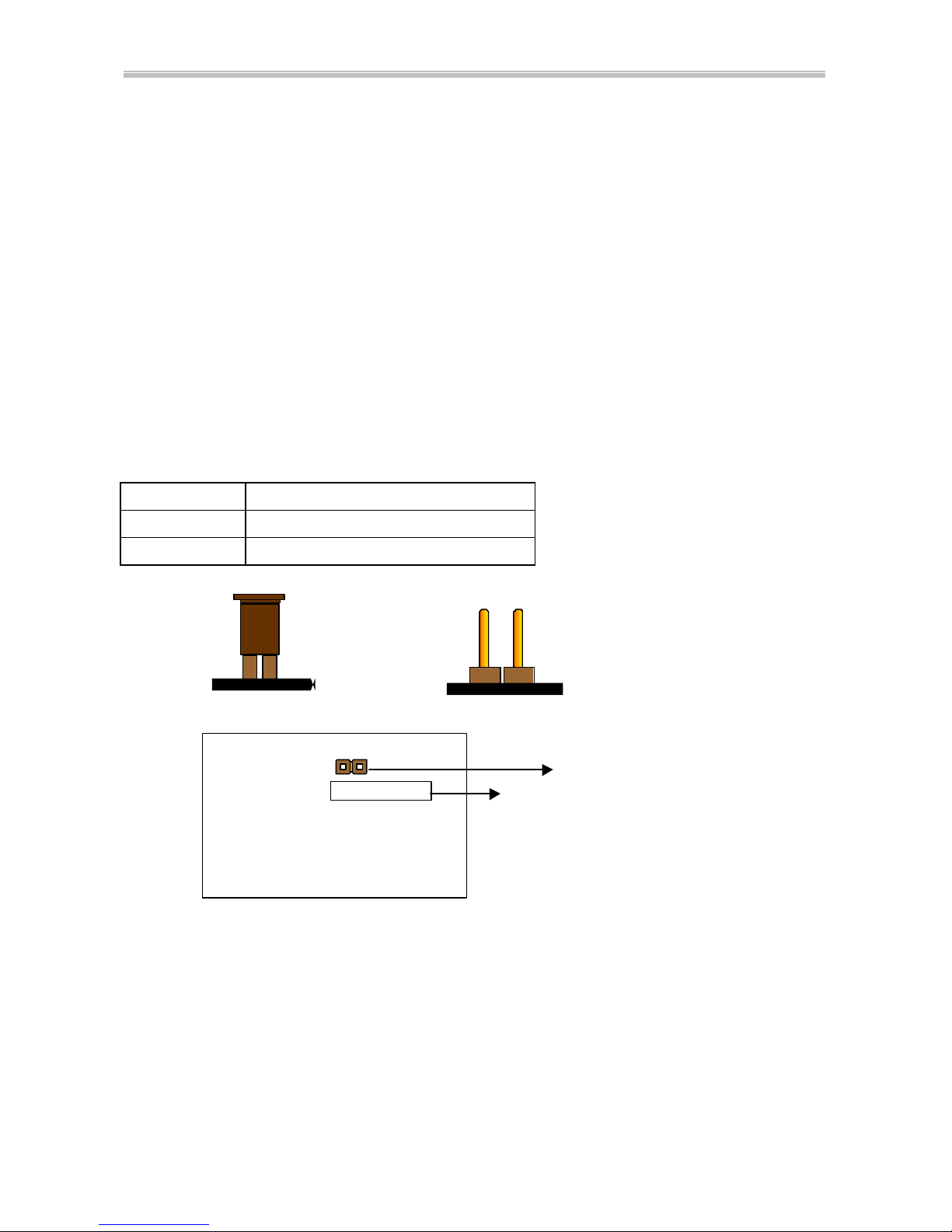
* Under Software power off control, the status of Power LED Light
depends on the setting of JP5.
If you set JP5 to “pin1-2” position, it is blinking. Otherwise, it is light
off.
Status Power LED Light Turbo LED Light
Software power off
control Blinking (JP5, pin1-2)
Light off (JP5, pin2-3) Light off
APM mode Light on Light on
System running Light on Light on
1-3 Fan Off Control
With fan-off function, the CPU cooling fan can turn off automatically even
when the system is in suspend mode. This function can reduce energy
consumption and system noise.
Because it is a feature of advanced BIOS, you should set this option
enabled through “Power Management Setup” from the BIOS setup screen. (An
ATX power supply is needed to achieve this function.)

6240M Mainboard Chapter 1 Introduction
5
1-4 Running 100 MHz CPU Bus on mainboard (JP11)
The mainboard provides Jumper 11 that allows you to set your CPU host
clock and perform CPU overclock function. When JP11 is ‘closed’, the system
will automatically detect the CPU host clock, for instance 66MHz and 100MHz.
When JP11 is ‘open’ it is for 66MHz CPU overclock to 100MHz.
We recommend that users should use Intel Pentium
II/III 100 MHz CPU,
running at 350, 400, 450 and 500MHz internal clock speed. Moreover, the
SDRAM memory module must be 8 nano-second (Maximum Frequency 125
MHz) speed of memory –die or less. However, based on Intel’s design, we don’t
recommend users to run over 100MHz CPU host bus.
Please note that the default setting of Jumper 11 is ‘closed’.
Jumper 11BASE CLK
ClosedAuto (default)
Open Overclock (66MHzà100MHz)
(a) Pin Closed (b) Pin Open
Slot 1
-If you would like to run over 100MHz CPU host bus, like 112 and 124MHz, please
set “CPU Host Clock” in “CHIPSET FEATURES SETUP” from the BIOS setup
screen. If the system can’t boot up at CPU frequency that has been set, you can
press the ‘Insert” key to clear up the set frequency. After restarting the system, it
will operate at the default frequency.
JP11

Chapter 1 Introduction 6240M Mainboard
6
1-5 SB-Link Sideband Signals
In order to migrate the legacy Sound Blaster compatible audio to the PCI
bus, EMU8008 incorporates a pair of SB-Link request/grant sideband signals
(PCPCIR EQN and PCPCIGNTN) to interface to the PCI bus. SB-Link is a
mechanism that was defined and developed by INTEL as a docking solution
which allows ISA slots to exist in docking stations connected to desktop PC PCI
bus.
ISA Slots PCI Slot SB-Link 2x3 sideband header, sound will also
has a 2x3 header and a cable.
1-6 Modem Ring On
With Modem Ring On function, the computer can wake up remotely
through the connected modem. This function enables users to access their
computer data from anywhere in the world. But users have to set “Resume by
Ring” with ‘enabled’ in “Power Management Setup” from the BIOS setup
screen. ( An ATX power supply is needed to achieve this function.)
SIRQ
REQ#
GND
GNT#A GND

6240M Mainboard Chapter 1 Introduction
7
1-7 Keyboard & PS/2 Mouse Power On (JP9)
With ATX Power Supply and Jumper 9 set to Pin 1-2 closed, 6240M
Mainboard is enabled to Keyboard & PS/2 Mouse Power On functions :
JP 9 KB & PS/2 Mouse Wakeup
1-2Enable
2-3Disable
(a) Enable (b) Disable
The default Power On function is “Button Only”. That means, we can only
turn our computer on and off by pressing the “Power Button”. If we want to
enable KB & PS/2 Mouse Power On function, we first have to set JP9 to Pin 1-2
closed, and then go to “Power On Function” in “Integrated Peripherals” of
Award BIOS Setup. At the line “Power On Function”, we can press “Page Up”
or Page Down” to make the following selections:
1. Password(via Keyboard):
When user selects “Password”, it will show “Enter Password:”. After user
has typed the password, screen will show “ Confirm Password:” and user has
to type the same password to confirm it. Save selection and shut down system.
Now computer will only be powered on by entering correct password.
In case the set password is forgotten, carry out “Clear CMOS” (Page 14) to
clear password, or computer can not be powered on.
2. Hot Key (via Keyboard):
When user selects this option, screen will show another line : “Hot Key
Power ON : Ctrl-F1”. User can select from “Ctrl-F1” to “Ctrl-F12” as Hot
Key by pressing PageUp / PageDown. After fixing Hot Key, save selection
and shut down system. Now computer will only be powered on by pressing the
correct Hot Key.
3. Mouse Left, Mouse Right (via PS/2 Mouse):
This function is available via PS/2 mouse only. User can select either “Mouse
Left” or “Mouse Right” from the “Power On Function” line. After picking
either option, save selection and shut down system. Now computer will only
be powered on by double-clicking the correct PS/2 Mouse button.
Do not slide the mouse when you click; or you can’t power on the system.
4. Button Only (via Power Button): “Button Only” is default setting, at which
computer can only be on/off via Power Button.
JP9
ISA
PCI slot

Chapter 1 Introduction 6240M Mainboard
8
1-8 Wake-On-LAN
The remote Wake-On-LAN mode of operation is a mechanism that uses
Advanced Micro Device Magic Packet technology to power on a sleeping
workstation on the network. This mechanism is accomplished when the LAN
card receives a specific packet of information, called a Magic Packet,
addressed to the node on the network. For additional protection, Secure ON is
an optional security feature that can be added to the Magic Packet that
requires a password to power on the sleeping workstation. When LAN card is
in remote Wake-On-LAN mode, main system power can be shut down leaving
power only for the LAN card and auxiliary power recondition.
The LAN card performs no network activities while in the remote
Wake-On-LAN mode of operation. It only monitors the network for receipt of a
Magic Packet. If a Magic Packet is addressed to the LAN card on the network,
the LAN card wake up the system. If the Secure ON feature has been enabled,
the password added to the Magic Packet is also verified prior to waking up the
system.
You should select two kinds of PCI Ethernet cards with WOL function.
One is Intel and the other is with PME signal supporting. And you can set
“PCI PME# Function” this function enabled through “ Power Management
Setup” from the BIOS setup screen.
1-9 Thermister (option)
This means that user can monitor the CPU temperature through
thermister.
When setting up the thermister (refer to Appendix B), the BIOS will load
the CPU temperature automatically. There is a choice of the warning beep
sound if the user set the option on. If the CPU temperature overheated, the user
will get the notice .This time you should shut down computer and check your
devices. Or you can connect with you dealer.
Therefore, monitoring the CPU temperature is the thermister’s job.
Note: If you would like to enable the function of hardware monitor, to set up
thermister beforehand is necessary.

6240M Mainboard Chapter 1 Introduction
9
1-10 LDCM (LANDesk Client Manager)(option)
The mainboard built-in controller support Intel LDCM. LDCM can satisfy
users who want manageable systems that can interact automatically with the
user. Client manager is the answer, enabling both administrators and clients to
manage systems. The features of LDCM are as following :
※View system inventory
Client Manager enables you to view hundreds of inventoried items. Some of
these items are software related, while many others are hardware related.
※View DMI-compliant component information
Client manager enables you to view component information that is compliant
with the Desktop Manager Interface
(
DMI
)
. This means you can manage
third-party DMI-compliant components which did not include Client
manager.
※Back up and restore system configuration files.
Client Manager enables you back up and restore system configuration files.
Whenever you plan on changing the system configuration , you can make a
backup set. If the system no longer works correctly, after you the change
the system configuration , you can simply restore the system configuration
with the backup set.
※Troubleshoot
Since Client manager enables you to view the system inventory, you can easily
troubleshoot system problems.
※Receive notifications for system events
Client manager enables you to receive notification of certain system events. For
example, if the system is running low on virtual memory, you are notified of
the potential problem.
※Transfer files to and from client workstations
As an administrator, you have the ability to transfer files to and from client
workstation. This is helpful, for example, when you need to update a client
workstation driver.
※Remotely reboot client workstations
Administrator also have the ability to remotely reboot a workstation. This is
helpful when you want your system configuration changes to take effect.

Chapter 2 Installation 6240M Mainboard
10
CHAPTER 2 INSTALLATION
2-1 INSTALLATION PROCEDURE
Before installing the computer, please prepare all components such as CPU, DRAM;
peripherals such as hard disk drive, keyboard, CD-ROM and accessories such as
cables. Then, install the system as following:
ŒPlug CPU/ heat sink (refer to PentiumIII, PentiumII & CeleronTM
installation guide, Appendix A), and DRAM modules on the
mainboard.
•Set DIP switch & jumpers based on your configuration.
ŽPlug add-on cards into PCI/ISA slots, if needed.
•Connect cables to peripheral devices, especially for power supply.
•Make sure all components and devices are well connected, turn on the
power and setup System BIOS based on your configuration.
‘Install peripheral devices, add-on card drivers and test them.
’If all of above procedures are running successfully, turn the power off
and screw the chassis cover to the chassis, and then connect external
devices which are cabled to the system.
Note: PCI slot 2 share the same interrupt number (INT#) with the
onboard sound. For this sake, please plug the card which is able to
share an INT# or needn’t use an INT# in PCI slot 2.
2-2 CPU INSTALLATION
The mainboard has built-in VID (Voltage Identify) function to automatically
detect CPU voltages. Thus you do not have to set the CPU voltage setting.
2-2-1 CPU Core/Bus Freq. Ratio :
SW1
1-1
1-2
1-3
1-4
3.0x ON ON OFF OFF
3.5x ON ON ON OFF
4.0x OFF OFF OFF OFF
4.5x OFF OFF ON OFF
5.0x OFF ON OFF OFF
5.5x OFF ON ON OFF
6.0x ON OFF OFF ON
6.5x ON OFF ON ON
7.0x ON ON OFF ON
7.5x ON ON ON ON
8.0x OFF OFF OFF ON

6240M Mainboard Chapter 2 Installation
11
2-2-2 CPU Setting
a. For 233~333MHz Intel PentiumII & 266~466MHz CeleronTM CPUs.
INTERNAL CPU CLOCK SW1
233MHz (66x3.5)
266MHz (66x4.0)
300MHz (66x4.5)
333MHz (66x5.0)
366MHz (66x5.5)
400MHz (66x6.0)
433MHz (66x6.5)
466MHz (66x7.0)
b. For 350~450MHz Intel PentiumII and 450~500MHz PentiumIII CPUs.
INTERNAL CPU CLOCK SW1 Setting Illustration
350MHz(100x3.5) On On On Off
400MHz(100x400) Off Off Off Off
450MHz(100x4.5) Off Off On Off
500MHz(100x5.0) Off On Off Off
550MHz(100x5.5) Off On On Off
1 2 3 4
ON
OFF
1 2 3 4
ON
OFF
1 2 34
ON
OFF
1 2 3 4
ON
OFF
1 2 3 4
ON
OFF
1 2 3 4
ON
OFF
1 2 3 4
ON
OFF
1 2 3 4
ON
OFF
1 2 3 4
ON
OFF

Chapter 2 Installation 6240M Mainboard
12
2-3 SYSTEM MEMORY INSTALLATION
6240M Mainboard provides four 168-pin DIMM sockets for system memory
expansion from 8MB to 512MB SDRAM, 1GB registered SDRAM or 1GB
EDO DRAM.(EDO DRAM is available for 66MHz processors only.) These
four DIMMs are arranged to four banks, please refer to page A.
Bank/DIMM Memory Module Total Memory
Bank0/DIMM1 8/16/32/64/128/256MB 8MB~256MB
Bank1/DIMM2 8/16/32/64/128/256MB 8MB~256MB
Bank2/DIMM3 8/16/32/64/128/256MB 8MB~256MB
Bank3/DIMM48/16/32/64/128/256MB 8MB~256MB
Total System Memory 8MB~1GB
DRAM type, size, parity supported:
6
EDO DRAM: for 66MHz system frequency only
6
Unbuffered, registered SDRAM with SPD
6
Both parity or non-parity are available.
6
3.3V, Single/double-side, 8/16/32/64/128Mbytes
(Max. memory size: 256MB registered SDRAM or EDO DRAM)
6Both 4Mbx4 and 16Mbx4 (Each side has 16 chips.) SDRAM devices are
supported in the form of Registered DIMMs only.
uFor 66MHz host bus CPUs use 12ns or faster DIMM module;
uFor 100MHz host bus CPUs use 10ns or faster and PC-100 compliant modules .
@SPD (Serial Presence Detect)
This EPROM contains speed and design information of the memory module.
The mainboard may get optimal performance via accessing the data of SPD.
@ECC (Error Check and Correction)
This mainboard can support the ECC function while utilizing parity modules.
To enable this function, users must set “DRAM Data Integrity Mode”to
“ECC”through “Chipset Features Setup”from the BIOS setup screen. All in
all, ECC’s function is to detect and correct the errors of transfer data.

6240M Mainboard Chapter 2 Installation
13
2-4 IDE DRIVER INSTALLATION
Setup for Windows 95/98 :
1. Start Windows 95/98.
2. Put the All-In-One CD into your CD-ROM drive.
3. Select “START”, “RUN”.
4. Type “D:\IDE\WIN95\SETUP.EXE” or “E:\IDE\WIN95\SETUP.EXE”.
(If your operating system is Win95, please type “D or E:\winp2x4.exe”
before you install IDE driver.)
5. Restart the computer, then follow the instructions on your screen to install
new IDE driver we offer in the All-In-One CD.
6. Exit Windows 95/98, turn power off; then turn power on.

Chapter 3Award BIOS Setup 6240M Mainboard
14
CHAPTER 3 AWARD BIOS SETUP
Award BIOS manufacturer provides access to the system BIOS through the
hardware and software on the mainboard. The hardware consists of a Flash
ROM and the software is a group of programs incorporated in the ROMBIOS
along with all the other data that the BIOS has to include.
After the BIOS is updated, if you want to clear the old setup data stored in the
CMOS, then you can clear CMOS.
NOTE : In case CMOS should be cleared, unplug the power cord, set Jumper 8
2-3 closed for at least 5 seconds, put it back to 1-2 position and plug the power
cord again.
JP8
Normal 1-2
Clear 2-3
Normal CMOS Clear CMOS
ISA Slots
JP 8
PCI Slot

6240M Mainboard Chapter 3Award BIOS Setup
15
3-1 UPDATE BIOS PROCEDURE
If the BIOS needs to be updated, you can get a CD with the updated BIOS
utility in the package. The updated BIOS utility includes :
“awdflash.exe” -- BIOS update utility program
“awdflash.doc”
The update procedure is as following:
1. Boot the system to DOS mode in a normal manner.
2. Insert the updated CD to drive D (or E).
3. Change working directory to CD-ROM drive, D or E, which contains the
update BIOS CD. -- Type “d:\” or “e: \”, then press “ENTER”.
4. Type “cd flash”, then press “ENTER”.
5. Type “awdflash”, then press “ENTER”-- for running the BIOS update
utility.
6. Type “(update BIOS file name with version number).bin”, ENTER.
7. If you do not want to save the old BIOS, type “N” when the screen displays
the message : " Do you want to save BIOS (Y/N) ?".
8. Type “Y“ when the screen shows the message : " Are you sure to program
(Y/N) ?".
9. Follow instructions displayed on the screen. DO NOT remove the update
BIOS CD from the CD-ROM drive nor turn the system power off until the
BIOS update is completed.
10.Turn the power off. Clear the data in CMOS according to the procedure
described in the previous page.
11.Turn the system power on and test that your system is working properly.

Chapter 3Award BIOS Setup 6240M Mainboard
16
3-1-1 UPDATE MICROCODE API
Intel also provides MICROCODE API (Applications Programming
Interface) for mainboard user to update data block in BIOS quickly and easily.
(You can find this utility in the All-In-One CD in the mainboard package).
The BIOS code on the mainboards contains data that is specific to each
silicon stepping of the processor. Integrators must ensure that this BIOS
stepping data matches the used processor stepping. When the BIOS does not
contain stepping data that matches the processor stepping, integrators must
update the data in the BIOS before shipping the system. Historically, systems
have been updated by replacing the entire BIOS with a new revision of BIOS
that contains the correct stepping data.
Intel‘s BIOS update API allows just the stepping data within the BIOS to
be updated as needed. Mainboards that contain a BIOS with the Intel-defined
BIOS update API can be quickly and easily updated, if required, without
obtaining a complete BIOS upgrade. Using this utility, integrators can easily
verify that the correct stepping data is present in all mainboards. However, if
the stepping data requires to be updated, the mainboard BIOS must contain the
Intel-defined BIOS update API, otherwise a complete BIOS upgrade is required
from the mainboard vendor.
Since API program can only be executed under DOS Real Mode, you must
enter Real Mode first and load the API program to Drive C.
To load the program to C by following steps:
(1)Type “ md c:\api ” and press Enter. Directory “api” is made in Drive C
now.
(2)Insert the Driver/Utility CD into CD ROM Drive E.
(3)Then type “ copy e:\api\*.* c:\api ” and press Enter.
(API program is loaded to Drive C now.)
(4) Type “ C:\api \checkup ” to execute this program.
The main menu should now be displayed with the following four options :
1) Check and load update
2) Specify stepping data file [current : pep.pdb]
3) Help
4) Quit without loading update
Select 1 to know the stepping filename, select 2 to load right patch code,
then select 1 to update proper patch code. Now, the screen will show the
message “please remove the CD from CD-ROM drive”. Then cold boot
(mechanical power off) system to continue. For more information, please refer
to “CHECKUP.HLP“ file.

6240M Mainboard Chapter 3Award BIOS Setup
17
3-2 SYSTEM BIOS CONFIGURATION SETUP
The following pages explain how to set up the BIOS configuration under
the Award BIOS. The SETUP program is stored in the Read-Only-Memory
(ROM) on the mainboard. To do the SETUP procedure, press the <Del> key
when the system is booting up. The following main menu will appear. Please
select " STANDARD CMOS SETUP" to enter the next screen.
ROM PCI/ISA BIOS
CMOS SETUP UTILITY
AWARD SOFTWARE, INC.
STANDARD CMOS SETUPINTEGRATED PERIPHERALS
BIOS FEATURES SETUP SUPERVISOR PASSWORD
CHIPSET FEATURES
SETUP USER PASSWORD
POWER MANAGEMENT
SETUP IDE HDD AUTO DETECTION
PNP/PCI CONFIGURATION
SAVE & EXIT SETUP
LOAD BIOS DEFAULTS EXIT WITHOUT SAVING
LOAD SETUP DEFAULTS
ESC: Quit
áâà ß
:Select Item
F10: Save & Exit Setup (Shift) F2 : Change Color
Time, Date, Hard Disk Type .....
The section on the bottom of the main menu explains how to control this screen.
The other section displays the items highlighted in the list.

Chapter 3Award BIOS Setup 6240M Mainboard
18
STANDARD CMOS SETUP This screen records some basic hardware
information, and sets the system clock and error handling. These records can
be lost or corrupted if the on-board battery has failed or is weak.
ROM PCI/ISA BIOS
STANDARD CMOS SETUP
AWARD SOFTWARE, INC.
Date (mm:dd:yy) : Wed, May 5 1999
Time(hh:mm:ss) : 13 : 37 : 14
HARD DISKS TYPE SIZE CYLS HEAD PRECOMP LANDZ SECTOR MODE
Primary Master : Auto 0 0 0 0 0 0 Auto
Primary Slave : Auto 0 0 0 0 0 0 Auto
Secondary Master : Auto 0 0 0 0 0 0 Auto
Secondary Slave : Auto 0 0 0 0 0 0 Auto
Drive A : 1.44M, 3.5 in.
Drive B : None Base Memory : 640K
Floppy 3 Mode Support : Disabled Extended memory : 7168K
Other Memory : 384K
Video : EGA/VGA ------------------------------------------------
Halt On: All Errors Total Memory : 8192K
ESC : Quit áâàß:Select Item PU/PD/+/-: Modify
F1 : Help (Shift) F2 : Change Color
Date The date format is <day>,<date>,<month>,<year>. Press<F3> to show
the calendar.
day The day, from Sun to Sat, determined by the BIOS and is displayed-only
date The date, from 1 to 31
month The month, Jan. through Dec.
year The year, from 1900 to 2099
Time The time format is <hour><minute><second>. The time is calculated
based on the 24-hour military-time clock. For example, 1p.m. is 13:00:00.
Primary Master Primary; Slave Secondary Master Secondary Slave
These categories identify the types of the 2 channels that have been installed in
the computer. There are 45 predefined types and 4 user definable types for
Enhanced IDE BIOS. Type 1 to 45 which are predefined. Type ‘user’ which is
user-definable. Press PgUp/PgDn to select a numbered hard disk type or type

6240M Mainboard Chapter 3Award BIOS Setup
19
the number and press <Enter>. If you select ‘Auto’, the BIOS will detect the
HDD & CD-ROM Drive automatically at the POST stage and show the IDE for
HDD & CD-ROM Drive. If you select ‘user’, you will need to know the
information listed below. This information should be from your hard disk
vender or dealer. Then enter the figure directly and press <Enter>. If the
controller of the HDD interface is ESDI, the selection shall be ‘Type 1’; if SCSI,
the selection shall be ‘None’. If no device is installed select ‘NONE’ and press
<Enter>.
Type drive type
SIZE automatically adjusts
CYLS number of cylinders
HEAD number of heads
PRECOMP
write precom
LANDZ landing zone
SECTOR number of sectors
MODE mode type
Drive A, Drive B This category identifies the types of floppy disk drive A or
drive B that has been installed in the computer.
None No floppy drive installed
360K, 5.25 in 5.25“ PC-type 360KB capacity
1.2M, 5.25 in 5.25“ AT-type 1.2MB capacity
720K, 3.5 in 3.5“ double-side 720KB capacity
1.44M, 3.5 in 3.5“ double-side 1.44MB capacity
2.88M, 3.5 in 3.5“ double-side 2.88MB capacity
Floppy 3 Mode Support This is the Japanese standard floppy drive. This
standard stores 1.2MB in a 3.5” diskette.
Video This category selects the type of video adapter used for the primary
system monitor. Although secondary monitors are supported, you do not have to
select the type in Setup.
EGA/VGA Enhanced Graphics Adapter/Video Graphics Array. For EGA, VGA,
SEGA, SVGA or PGA monitor adapters
CGA 40 Color Graphics Adapters, power up in 40 column mode
CGA 80 Color Graphics Adapters, power up in 80 column mode
MONO Monochrome adapter, includes high resolution monochrome adapters

Chapter 3Award BIOS Setup 6240M Mainboard
20
Halt On This category determines whether the computer will stop if an error is
detected during power up.
No errors The system boot will not be stopped for any error that may be
detected.
All errors When the BIOS detects a non-fatal error, the system will be
stopped and you will be prompted.
All, But
Keyboard The system boot will not stop for a keyboard error. It will stop for
all other errors.
All, But
Diskette The system boot will not stop for a floppy drive error. It will stop
for all other errors.
All, But
Disk/Key The system boot will not stop for a floppy drive or keyboard error.
It will stop for all other errors.
Memory
This category is displayed only which is determined by POST (Power
On Self Test) of the BIOS.
Base Memory
The POST will determine the amount of base (or conventional)
memory installed in the system. The value of the
base memory is typically 512K
or 640K based on the memory installed on the motherboard.
Extended Memory
How much extended memory is present during the POST.
This is the amount of memory located above 1MB in the CPU‘s memory
address map.
Other Memory This
refers to the memory located in the 640K to 1024K
address space. This is memory that can be used for different applications. DOS
uses this area to load device drivers in an effort to keep as much base memory
free for application programs. The BIOS is the
most frequent user of this RAM
area since this is where it shadows RAM.
Table of contents
Other A-Trend Motherboard manuals

A-Trend
A-Trend ATC-6320 User manual

A-Trend
A-Trend 6253M User manual

A-Trend
A-Trend ATC-6510 User manual

A-Trend
A-Trend ATC-6260 User manual

A-Trend
A-Trend 6220M User manual

A-Trend
A-Trend atc-1020 User manual

A-Trend
A-Trend ATC6240V User manual

A-Trend
A-Trend ATC-2000 User manual

A-Trend
A-Trend 6241 User manual

A-Trend
A-Trend ATC-6130E User manual
Popular Motherboard manuals by other brands

Analog Devices
Analog Devices EVAL-SSM3582Z user guide

Abit
Abit IS-10 Intel Pentium 4 System Board Socket... user manual

EMC
EMC AX100 Series manual

IEI Technology
IEI Technology HYPER-BW Quick installation guide

Intel
Intel D945GCLF - Desktop Board Essential Series... specification

Linear Technology
Linear Technology DC2160A Demo Manual