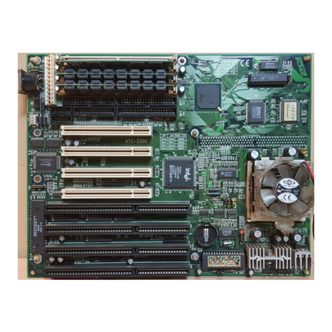
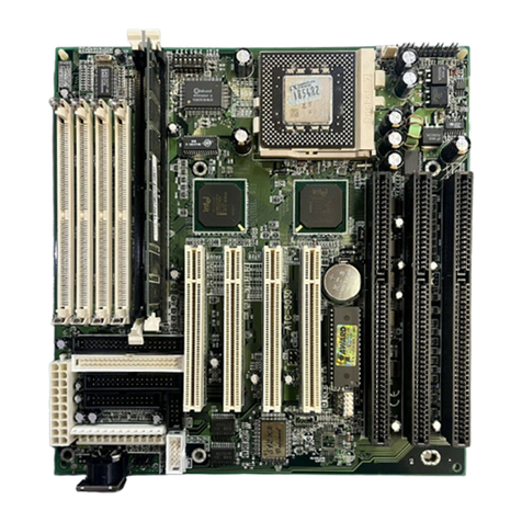
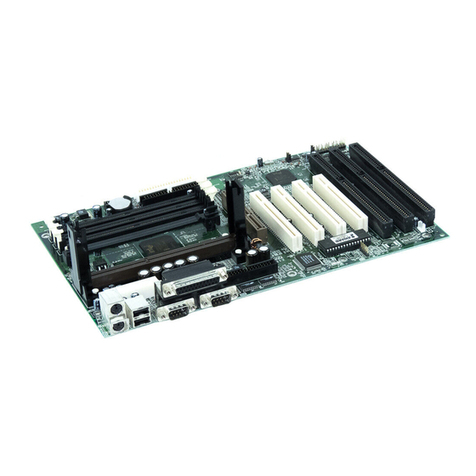
A-Trend ATC5200M User manual

How To Use ATC5200M Mainboard User’s Manual
HOW TO USE THIS MANUAL
This manual is written in a user-friendly style. It would e
advisa le for users to read it in an orderly sequence :
1. For Hardware Information:
Read COMPONENT LOCATION DIAGRAM, Pa e B : QUICK JUMPER &
CONNECTOR SETTING, Pa e C & D : CONNECTORS AND JUMPERS
DESCRIPTION and Pa e E:List of Packa in .
2. For Mainboard and System Features:
Read “Chapter 1 System Features” , and you will find helpful information
on mainboard and system features. Especially, when you want to do some
feature setup, detailed instructions are provided therein to help you through.
3. For CPU, Memory and Drivers Installation:
Read “Chapter 2 Installation” for your CPU, memory and application drivers
installation. etailed instructions are provided to guide all kinds of users.
4. For BIOS Update and Setup:
Read “Chapter 3 Award BIOS Setup” for updating your mainboard BIOS and
setting up your BIOS Configuration.
5. For other Technical Support:
See “Appendix A” , fill and send the Request Form to your dealer for other technical
support.
The default settings on a mainboard is not necessarily what user expects. A user-
friendly manual would be the handiest assistant to help change the on-board
configuration or default setting. In case this manual cannot solve all your problems,
please ask your dealer for help and be sure the warranty on your system is still valid.
REMARK: Intel® is a registered trademark of Intel Corporation.
All other brands and product names are registered trademarks of their respective companies

ATC5200M Mainboard Contents
CONTENTS
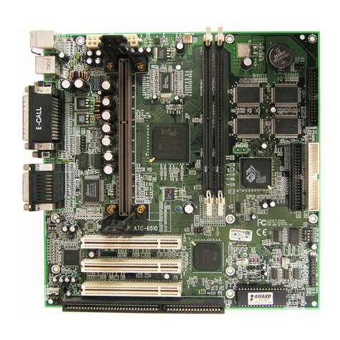
PICTURE OF THE MAINBOARD …………………………..A
QUICK JUMPER & CONNECTOR SETTING......................B
CONNECTORS AND JUMPERS DESCRIPTION………..C,D
CHECKLIST OF PACKAGING.................................................E
HOW TO USE THIS MANUAL
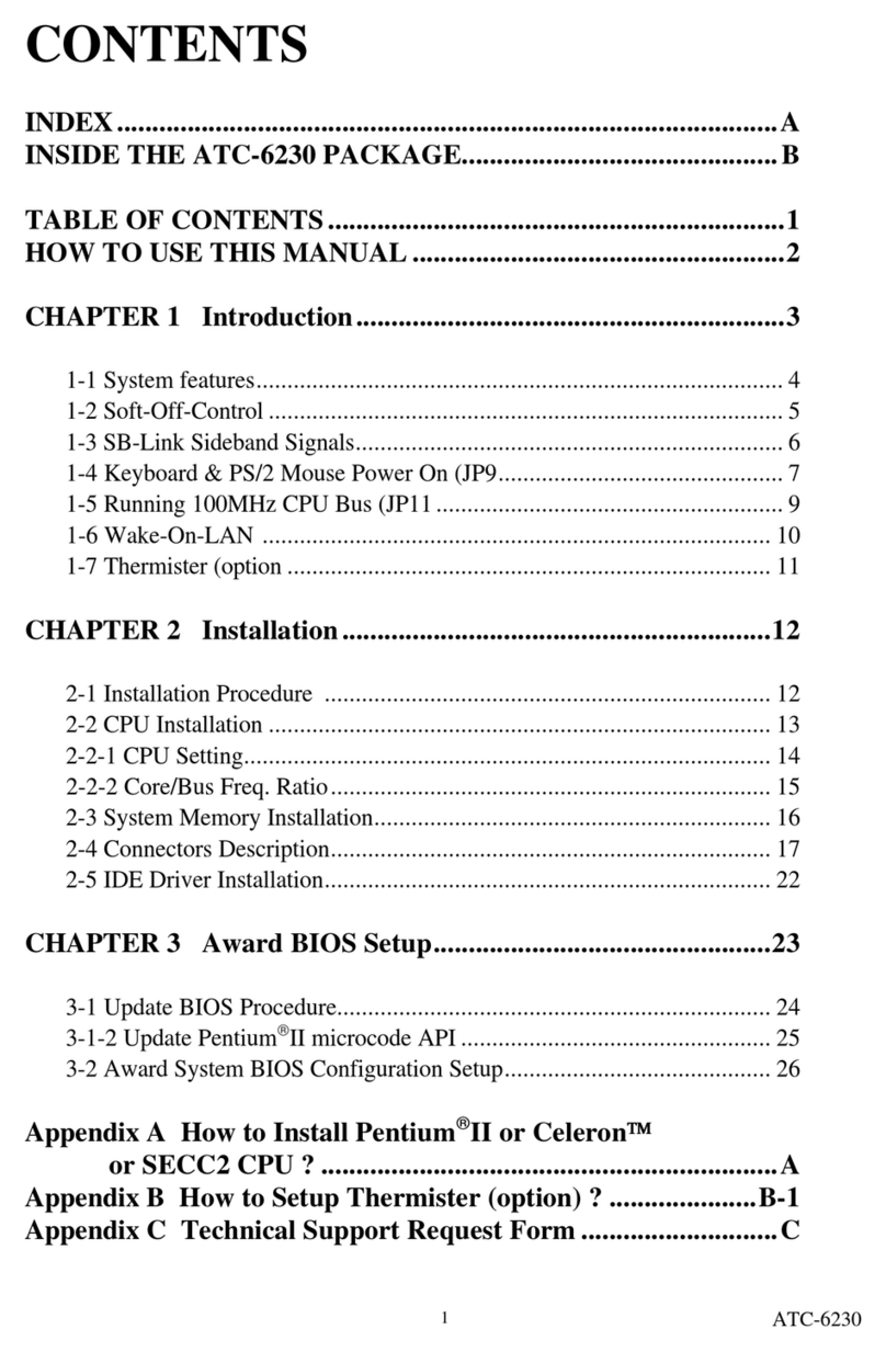
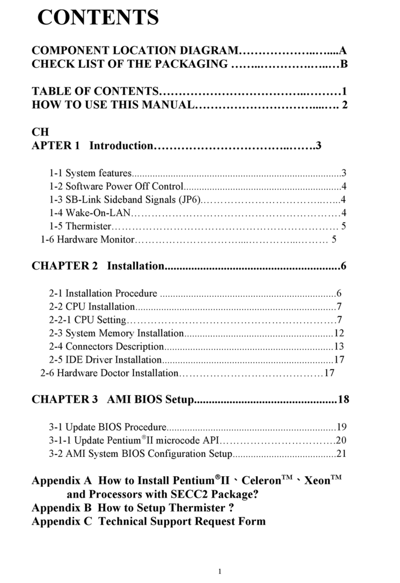
TABLE OF CONTENTS:
Chapter 1 System Description
1-1 ATC5200M Mainboard Specification ……………………………………………………... 1
1-2 Features Highlight ………………………………………………………………………….. 2
1-2-1 Software Power Off Control …...………………………………………………………… 2
1-2-2 AGP Interface ……………..……………………………………………………………... 2
Chapter 2 Installation
2-1 Mainboard Installation ……………………………………………………………………... 3
2-2 CPU Configuration ………………………………………………………………………… 4
2-3 System Memory Installation ………………………………………………………………. 20
2-4 VIA I E river Setup ……………………………………………………………………... 21
2-4-1 Setup for Windows 9X………………………………………………………………… 21
2-4-2 Setup for Windows NT4.0 ……………………………………………………………. 22
Chapter 3 AWARD BIOS Setup
3-1 Update BIOS Procedure ……………………………………………………... 24
3-2 System BIOS Configuration ……………………………………………………………….. 25
3-2-1 Standard CMOS Setup ………………………………………………………………… 26
3-2-2 BIOS Features Setup ………………………………………………………………….. 29
3-2-3 Chipset Features Setup ………………………………………………………………... 33
3-2-4 Power Management Setup …………………………………………………………….. 35
3-2-5 PNP/PCI Configuration ……………………………………………………………….. 38

Contents ATC5200M Mainboard
3-2-6 Integrated Peripherals …………………………………………………………………. 40
3-2-7 I E H Autodetection ……………………………………………………………… 42
3-2-8 Save & Exit Setup ……………………………………………………………………... 43
3-2-9 Load BIOS efaults …………………………………………………………………... 43
3-2-10 Load Setup efaults …………………………………………………………………. 43
3-2-11 Supervisor/User Password …………………………………………………………… 43
3-2-12 Exit without Saving ………………………………………………………………….. 43
Control Keys Description for BIOS Setup ………………………….. 44
Appendix A Technical Support Request Form

ATC5200M Mainboard Chapter 1 System Description
CHAPTER 1
System Description
ATC5200M Mainboard with Soc et 7 on board supports 66~100MHz host cloc ,
and is intended to run Intel Pentium CPUs up to 233MHz, AMD K5/K6/K6-2
CPUs, and Cyrix 6x86/6x86MX / M II CPUs. With VIA MVP3 chipset on
board, it also supports AGP and Ultra DMA performance for fast VGA display
and data transfer. Below are detailed description of its system specifications and
features.
1-1 SYSTEM SPECIFICATION
Supports Intel Pentium (P54C) CPUS up to 200MHz, Intel Pentium MMX
166~2 MHz (P55C), AMD K5, AMD K6, AMD K6-2, Cyrix 6x86MX, MII,
6x86L, IDT Win Chip C6 CPUs.
Supports CPU Bus Clock from 66MHz to 100MHz and Ratio from 1.5x to 5.5x
VIA @ VT82C598MVP & VT82C586B (with keyboard control) chipset.
Built-in Switching Voltage Regulator.(VRM 8.2 SPEC.)
CPU core voltage support: 2.2V~ .5V; CPU/IO Voltage: .40V
Three 168-pin DIMM sockets on board, supporting three banks of 64-bit wide
path up to 84MB SDRAM or 768 EDO DRAM (with parity chip ECC support).
L2 Cache: 512KB, . V
AGP slot on board; three PCI slots with revision 2.1 interface compliance and two
16-bit ISA slots.
Dual Master IDE connectors support Ultra DMA/ , up to four devices in two
channels for connecting high capacity hard drive, CD-ROM, tape backup etc.
One USB (Universal Serial Bus) header supporting up to 127 devices.
AT style keyboard connector and PS/2 mouse header.
1

Chapter 2 Installation ATC5200M Mainboard
WINBOND W8 877TF high-speed Super Multi-I/O chipset.
Infrared transfer (IrDA TX/RX) Support.
One FDD port supports following 2 floppy drives: 1.2MB/1.44MB/ 2.88MB.
Two 16550A fast UARTs compatible serial ports; One DIN connector for KB
AT & ATX power connectors on board.
Hardware Dimension :220mm x 2 0mm (8.66" x 9.0"); BabyAT Form Factor.
1-2 FEATURES HIGHLIGHT
1-2-1 Software Power Off Control (under ATX power supply)
This mainboard supports Software Power Off Control feature through the SMM code
in the BIOS under Windows 95/98, and MS-DOS operation system environment. It
needs ATX power supply to support this performance.
First, you should connect the power switch cable to the connector “PS-ON” on the
mainboard. In the BIOS screen of POWER MANAGEMENT SETUP’, choose “User
Defined” (or “Min. Power Saving” or “Max. Power Saving”) in ‘Power Manager’ and
choose “Yes” in ‘PM Control by APM’.
In Windows 95/98, if you want to power off the system, you just choose “shutdown
the computer ?” in the “Shut Down Windows“ from Windows 95/98, then the system
power will be off directly and stay at the stand-by status. If you want to restart the
system, just press the power switch button, and the system will be powered on.
In case you leave your system idle for several days, you better use “Hardware
Power Off” to shut down your system.
1-2-2 AGP (Accelerated Graphics Port) Interface
AGP gives graphics accelerators fast, high throughput direct access to system
memory. This allows a graphics accelerator access to more memory than
available locally on the graphics card. For example, to display a scene that
contains 16MB of textures, a 4MB AGP graphics card could access the PC
system memory for the additional 12MB required.
AGP delivers a pea bandwidth that is 4 times higher than the PCI bus using
pipelining, sideband addressing, and more data transfers per cloc .
2

ATC5200M Mainboard Chapter 1 System Description
The current PCI bus supports a data transfer rate up to 132 MB/s,
while AGP (at 66MHz) supports up to 533 MB/s!

Chapter 2 Installation ATC5200M Mainboard
CHAPTER 2
INSTALLATION
2-1 MAINBOARD INSTALLATION
Before installing the computer, please get ready all components such as CPU,
DRAM; peripherals(such as hard drive, keyboard, CD-ROM) and accessories(such as
cables, jumper caps, cooling fans, screw driver)etc. Then, install the system as below:
1. Plug CPU, heat sink, cooling fan and DRAM modules onto the 5200M mainboard.
2. Set DIP switch based on your CPU configuration.
. Set jumpers based on your CPU and BIOS configuration.
4. Plug add-on cards into PCI/ISA slots, if needed.
5. Connect the power supply.
6. Connect I/O and other cables to the system.
7. Make sure all components and devices are well connected, turn on the power and
setup System BIOS based on your configuration.
8. Install peripheral devices, add-on card drivers and test them.
If all of above procedures are running successfully, turn it off and screw the chassis
cover to the system, and then connect external devices which are cabled to the system.
4

ATC5200M Mainboard Chapter 2 Installation
2-2 CPU CONFIGURATION
5200M Mainboard supports Pentium level CPUs.
To install CPU, please notice CPU pin 1 must align with the ZIF socket 7 pin 1
location. To configure your CPU, please follow the CPU Guide provided by CPU
manufacturer to configure the CPU voltage setting and then set up DIP Switch &
Jumpers on 5200M Mainboard to suit your CPU type.
It is very important you must set up DIP switch SW1, Jumpers JP2, JP3, JP4, JP5
accurately for a normal and stable CPU operation.
To locate these jumpers and SW1, please turn to Page A “Component Location Diagram”.
The following are illustrations of SW1 setting, as well as JP2,3,4, 5 settings.
SW1 setting: for CPU base frequency and CPU Frequency Ratio
CPU Frequency Ratio Settings CPU Base Frequency Settings
SW1 SW1-1 SW1-2 SW1- SW1 SW1-4 SW1-5 SW1-6
2.0X OFF OFF ON 66.6MHz ON ON OFF
2.5X OFF ON ON 75MHz OFF ON ON
.0X OFF ON OFF 8 .5MHz OFF ON OFF
1.5X; .5X OFF OFF OFF 95.25MHz OFF OFF ON
4.0X ON OFF ON 100MHz OFF OFF OFF
4.5X ON ON ON
5.0X ON ON OFF
5.5X ON OFF OFF
How to set up DIP switch SW1:
ON DIP
Off
1 2 3 4 5 6 7
JP2 & JP3 Setting:
(The setting for frequency-ratio comparing with the PCI clock and the CPU host clock.)
CPU_CLK/PCI_CLK JP 2 JP
66.6MHz/ . MHz Pin 2- Pin 2-
75MHz/ 0MHz Pin 1-2 Pin 1-2
8 . MHz/ . MHz Pin 1-2 Pin 1-2
95.25MHz/ 1.7MHz Pin 1-2 Pin 2-
100MHz/ . MHz Pin 1-2 Pin 2-
SW1 Settings Illustration:
DIP switch, (i.e. : OFF, OFF, OFF, ON,
ON, OFF, OFF)
5

Chapter 2 Installation ATC5200M Mainboard
JP4 Setting: For CPU Core voltage
The setting for CPU Ccore Voltage Selection
Vcore Pin1 & Pin5 Pin2 & Pin6 Pin3 & Pin7 Pin4 & Pin8
2.2V Open Closed Open Open
2.3V Closed Closed Open Open
2.7V Closed Closed Closed Open
2.8V Open Open Open Closed
2.9V Closed Open Open Closed
3.2V Open Open Closed Closed
3.3V Closed Open Closed Closed
3.5V Closed Closed Closed Closed
JP5 setting
(The setting for Single/Dual Voltage supporting for Pentium level Processor)
Mode JP5 (Pin1-2,3-4,5-6
Single Voltage Mode(Vcore = Vi/o * Open
Dual Voltage Mode(Vcore ≠Vi/o ** Closed
* P54C mode (Single Voltage Mode : supports for Intel Pentium, AMD-
K5,Cyrix 6X86, IDT Win Chip C6.
** P55C mode (Dual Voltage Mode : supports for Intel Pentium MMX,
AMD-K6, AMD-K6-2, Cyrix 6X86L,
Cyrix 6X86MX, Cyrix M II.
how to set up jumpers:
Open Closed
( remove the ( put on the Pin1-2 Pin2-3
jumper cap) jumper cap)
1 2 3
1 2 3
6

ATC5200M Mainboard Chapter 2 Installation
2-2-1 CPU TYPE vs Jumper Setting Illustrations:
A. INTEL PENTIUM CPU (P54C)
※P54C VRE : 3.400V~3.600V (CPU Voltage is marked on the back side
of the CPU itself. V = VRE, S = standard. )
JP4(3 5V)
JP4
Vcore
Pin1 & Pin5 Pin2 & Pin6 Pin & Pin7 Pin4 & Pin8
.5V Closed Closed Closed Closed
※ ※ P54C STD : 3.135V ~ 3.600V (CPU Voltage is marked on the back side
of the CPU itself. V = VRE, S = standard. )
JP4 (3 3V)
JP4
Vcore
Pin1 & Pin5 Pin2 & Pin6 Pin & Pin7 Pin4 & Pin8
. V Closed Open Closed Closed
JP5 Setting (Single)
Mode JP5 (Pin1-2, 3-4, 5-6
Single Voltage Mode(Vcore = Vi/o * Open
JP1, JP2 & JP3 Settings
CPU host clock/DRAM/PCI clock JP 1 JP 2 JP
66MHz/66MHz/ MHz Pin 2- Pin 2- Pin 2-
A-1. Intel Pentium 100MHz
CPU Cloc SW1 Base x Ratio.
100MHz ON
OFF
1 2 4 5 6 7
66 x 1.5
7

Chapter 2 Installation ATC5200M Mainboard
A-2. Intel Pentium 133MHz
CPU
CLOCK SW1 Base x Ratio
1 MHz
ON
OFF
1 2 4 5 6 7
66 x 2.0
A-3. Intel Pentium 166MHz
CPU
CLOCK SW1 Base x Ratio
166MHz ON
OFF
1 2 4 5 6 7
66 x 2.5
A-4. Intel Pentium 200MHz
CPU
CLOCK SW1 Base x Ratio
200MHz ON
OFF
1 2 4 5 6 7
66 x .0
8

ATC5200M Mainboard Chapter 2 Installation
B. INTEL PENTIUM MMXTM CPU (P55C)
JP4 (2 8V)
JP4
Vcore
Pin1 & Pin5 Pin2 & Pin6 Pin & Pin7 Pin4 & Pin8
2.8V Open Open Open Closed
JP5 Setting (Dual)
Mode JP5 (Pin1-2, 3-4, 5-6
Dual Voltage Mode(Vcore ≠Vi/o ** Closed
JP1, JP2 & JP3 Settings
CPU host clock/DRAM/PCI clock JP1 JP2 JP
66MHz/66MHz/ MHz Pin 2- Pin 2- Pin 2-
B-1. Intel Pentium MMXTM 166MHz
CPU CLOCK SW1 Base x Ratio
166MHz
ON
OFF
1 2 4 5 6 7
66 x 2.5
B-2. Intel Pentium MMXTM 200MHz
CPU CLOCK SW1 Base x Ratio
200MHz ON
OFF
1 2 4 5 6 7
66 x .0
B-3. Intel Pentium MMXTM 233MHz
CPU CLOCK SW1 Base x Ratio
2 MHz ON
OFF
1 2 3 4 5 6 7
66 x .5
9

Chapter 2 Installation ATC5200M Mainboard
C. Cyrix 6x86MX CPU
JP4 (2 9V)
JP4
Vcore
Pin1 & Pin5 Pin2 & Pin6 Pin & Pin7 Pin4 & Pin8
2.9V Closed Open Open Closed
JP5 Setting (Dual)
Mode JP5 (Pin1-2, 3-4, 5-6
Dual Voltage Mode(Vcore ≠Vi/o ** Closed
JP1, JP2 & JP3 Settings
CPU host clock/DRAM/PCI clock JP1 JP2 JP
66MHz/66MHz/ MHz Pin 2- Pin 2- Pin 2-
C-1. Cyrix 6x86MX PR166 @ 66MHz Bus 2x
CPU Cloc SW1 Base x Ratio
PR166 ON
OFF
1 2 4 5 6 7
66 x 2.0
C-2. Cyrix 6x86MX PR200 @ 66MHz Bus 2.5x
CPU Cloc SW1 Base x Ratio
PR200 ON
OFF
1 2 4 5 6 7
66 x 2.5
C-3. Cyrix 6x86MX PR233 @ 66MHz Bus 3x
CPU Cloc SW1 Base x Ratio
PR2 ON
OFF
1 2 4 5 6 7
66 x .0
10

ATC5200M Mainboard Chapter 2 Installation
C-4. Cyrix 6x86MX PR233 @ 75MHz Bus 2.5x
JP4 (2 9V)
JP4
Vcore
Pin1 & Pin5 Pin2 & Pin6 Pin & Pin7 Pin4 & Pin8
2.9V Closed Open Open Closed
JP5 Setting (Dual)
Mode JP5 (Pin1-2, 3-4, 5-6
Dual Voltage Mode(Vcore ≠Vi/o ** Closed
JP1, JP2 & JP3 Settings
CPU host clock/DRAM/PCI clock JP1 JP2 JP
75MHz/75MHz/ 0MHz Pin 2- Pin 1-2 Pin 1-2
CPU Cloc SW1 Base x Ratio
PR2 ON
OFF
1 2 4 5 6 7
75 x 2.5
11

Chapter 2 Installation ATC5200M Mainboard
D. Cyrix MII CPU
D-1 Cyrix MII 300MHz @ 66MHz Bus 3.5x
JP4(2 9V)
JP4
Vcore
Pin1 & Pin5 Pin2 & Pin6 Pin & Pin7 Pin4 & Pin8
2.9V Closed Open Open Closed
JP5 Setting (Dual)
Mode JP5 (Pin1-2, 3-4, 5-6
Dual Voltage Mode(Vcore ≠Vi/o ** Closed
JP1, JP2 & JP3 Settings
CPU host clock/DRAM/PCI clock JP1 JP2 JP
66MHz/66MHz/ MHz Pin 2- Pin 2- Pin 2-
CPU Cloc SW1 Base x Ratio
MII 300MHz ON
OFF
1 2 4 5 6 7
66 x .5
D-2 Cyrix MII 300MHz @ 75MHz Bus 3x
JP4(2 9V)
JP4
core
Pin1 & Pin5 Pin2 & Pin6 Pin & Pin7 Pin4 & Pin8
2.9V Closed Open Open Closed
JP5 Setting (Dual)
Mode JP5 (Pin1-2, 3-4, 5-6
Dual Voltage Mode(Vcore ≠Vi/o ** Closed
JP1, JP2 & JP3 Settings
12

ATC5200M Mainboard Chapter 2 Installation
CPU host clock/DRAM/PCI clock JP1 JP2 JP
75MHz/75MHz/ 0MHz Pin 2- Pin 1-2 Pin 1-2
CPU Cloc SW1 Base x Ratio
MII 300MHz ON
OFF
1 2 4 5 6 7
75 x .0
1

Chapter 2 Installation ATC5200M Mainboard
E. Cyrix 6x86L CPU (dual voltage)
JP4 (2 8V)
JP4
core
Pin1 & Pin5 Pin2 & Pin6 Pin & Pin7 Pin4 & Pin8
2.8V Open Open Open Closed
JP5 Setting (Dual)
Mode JP5 (Pin1-2, 3-4, 5-6
Dual Voltage Mode(Vcore ≠Vi/o ** Closed
JP1, JP2 & JP3 Settings
CPU host clock/DRAM/PCI clock JP1 JP2 JP
66MHz/66MHz/ MHz* Pin 2- Pin 2- Pin 2-
Cy ix 6x86L PR166+
CPU Cloc SW1 Base x Ratio
PR166+ ON
OFF
1 2 4 5 6 7
66 x 2.0
14

ATC5200M Mainboard Chapter 2 Installation
F. AMD-K5 CPU Series
JP4(3 5V)
JP4
Vcore
Pin1 & Pin5 Pin2 & Pin6 Pin & Pin7 Pin4 & Pin8
.5V Closed Closed Closed Closed
JP5 Setting (Single)
Mode JP5 (Pin1-2, 3-4, 5-6
Single Voltage Mode(Vcore = Vi/o * Open
JP1, JP2 & JP3 Settings
CPU host clock/DRAM/PCI clock JP1 JP2 JP
66MHz/66MHz/ MHz* Pin 2- Pin 2- Pin 2-
F-1. AMD-K5 PR100
CPU Cloc SW1 Base x Ratio
PR100 ON
OFF
1 2 4 5 6 7
66 x 1.5
F-2. AMD-K5 PR133
CPU Cloc SW1 Base x Ratio
PR1 ON
OFF
1 2 4 5 6 7
66 x 1.5
F-3. AMD-K5 PR166
CPU Cloc SW1 Base x Ratio
PR166 ON
OFF
1 2 4 5 6 7
66 x 2.5
15

Chapter 2 Installation ATC5200M Mainboard
G. AMD-K6 CPU
JP1, JP2 & JP3 Settings
CPU host clock/DRAM/PCI clock JP1 JP2 JP
66MHz/66MHz/ MHz Pin 2- Pin 2- Pin 2-
JP5 Setting (Dual)
Mode JP5 (Pin1-2, 3-4, 5-6
Dual Voltage Mode(Vcore ≠Vi/o ** Closed
G-1. AMD-K6 166MHz
JP4(2 9V)
JP4
Vcore
Pin1 & Pin5 Pin2 & Pin6 Pin & Pin7 Pin4 & Pin8
2.9V Closed Open Open Closed
CPU Cloc SW1 Base x Ratio
166MHz ON
OFF
1 2 4 5 6 7
66 x 2.5
G-2. AMD-K6 200MHz
JP4(2 9V)
JP4
Vcore
Pin1 & Pin5 Pin2 & Pin6 Pin & Pin7 Pin4 & Pin8
Vcore Closed Open Open Closed
CPU Cloc SW1 Base x Ratio
16

ATC5200M Mainboard Chapter 2 Installation
200MHz ON
OFF
1 2 4 5 6 7
66 x .0
G-3a. AMD-K6 233MHz
JP4(3 2V)
JP4
Vcore
Pin1 & Pin5 Pin2 & Pin6 Pin & Pin7 Pin4 & Pin8
.2V Open Open Closed Closed
CPU
CLOCK SW1 Base x Ratio
2 MHz ON
OFF
1 2 4 5 6 7
66 x .5
G-3b. AMD-K6-2 233MHz
JP4(2 2V)
JP4
Vcore
Pin1 & Pin5 Pin2 & Pin6 Pin & Pin7 Pin4 & Pin8
2.2V Open Closed Open Open
CPU
CLOCK SW1 Base x Ratio
2 MHz ON
OFF
1 2 4 5 6 7
66 x .5
17
Table of contents
Other A-Trend Motherboard manuals

A-Trend
A-Trend ATC-5030 User manual

A-Trend
A-Trend ATC-6510 User manual

A-Trend
A-Trend Atc-6240m Mounting instructions

A-Trend
A-Trend ATC-6320 User manual

A-Trend
A-Trend ATC-6400 User manual

A-Trend
A-Trend ATC-6120 User manual

A-Trend
A-Trend 6240V User manual

A-Trend
A-Trend 6220M User manual

A-Trend
A-Trend ATC-6230 User manual

A-Trend
A-Trend ATC-2000 User manual