9
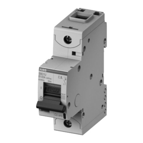
System pro M
S 280 UC thermal trips ➀electromagnetic trips ➁
acc. to tripping characteristics test current tripping time test currents tripping time
specification and range of rated current conventional conventional hold switch off
non-tripping
tripping current
current rushes of at the latest
I
1I
2at ...at ~ at – at ~ at –
DIN VDE 0641 B6 to 25 A 1.13 · In> 1 h 3 · In> 0.1 s > 0.1 s
Part 12 1.45 · In< 1 h 5 · In7.5 · In< 0.1 s < 0.1 s
DIN VDE 0660-101
K0.2 to 63 A 1.05 · In> 1 h 10 · In> 0.2 s > 0.2 s
1.2 · In< 1 h ➂14 · In21 · In< 0.2 s < 0.2 s
1.5 · In< 2 min
6.0 · In> 2 s (T1)
DIN VDE 0660-101
Z0.5 to 63 A 1.05 · In> 1 h 2 · In> 0.2 s > 0.2 s
1.2 · In< 1 h ➂3 · In4.5 · In< 0.2 s < 0.2 s
1.5 · In< 2 min
Tripping behavior
rated hold non-delayed tripping at
current current rushes AC/DC
from DC
48 % 5 %
ripple ripple
S 280 UC-Z 0.5 A 1 A 1.5 A 2.4 A
1 A 2 A 3.0 A 4.8 A
1.6 A 3.2 A 4.8 A 7.7 A
2 A 4 A 6 A 9 A
3 A 6 A 9 A 15 A
4 A 8 A 12 A 19 A
6 A 12 A 18 A 29 A
8 A 16 A 24 A 38 A
10 A 20 A 30 A 48 A
16 A 32 A 48 A 77 A
20 A 40 A 60 A 96 A
25 A 50 A 75 A 120 A
32 A 64 A 96 A 153 A
40 A 80 A 120 A 192 A
50 A 100 A 150 A 240 A
63 A 125 A 189 A 315 A
➀The max. permissible operating currents depend on the following factors:
Ambient temperature and mutual thermal interference.
see page 2/51
➁The indicated tripping values of electromagnetic tripping devices apply to a
frequency range from 16
2/3... 60 Hz. In the case of diverging frequencies or
direct current, the values change by the factor indicated in the table below.
➂As from operating temperature (after I1> 1 h)
AC
100 Hz 200 Hz 400 Hz DC
factor ca. 1.1 1.2 1.5 ca. 1.5
The thermal release operates independent of the frequency.
Miniature circuit-breakers
S 280 UC series
max. backup
protect. 햶for
backup protect.;
utilization cate-
gory gL (DIN VDE
0636/IEC 269)
Short circuit rupturing
Operating sequence for B according to DIN VDE 0641 Part 12 for K according to DIN VDE 0660 Part 101/p-2.
For the short circuit capacity indicated, in the case of DC, a time constant T = L/R 15 ms applies, in the case of AC for 10 kA: cos 0.6 for 6 kA: cos 0.7 – for 4.5 kA and
for 3 kA: cos 0.8 – for < 3 kA: cos 0.9.
S 280 UC 1-pole 2-pole
DC up to 60 V ... 110 V ... 220 V ... up to 60 V ... 110 V ... 220 V ... 440 V ...
B 6 ... 25 A 14 kA 10 kA 6 kA 25 kA 20 kA 10 kA 6 kA 100 A
Z, K 0.2 ... 2 A 햷unlimited unlimited unlimited unlimited unlimited unlimited unlimited not required
Z, K 3 ... 4 A 14 kA 10 kA 6 kA 25 kA 20 kA 10 kA 6 kA 35 A
Z, K 6 ... 8 A 14 kA 10 kA 6 kA 25 kA 20 kA 10 kA 6 kA 63 A
Z, K 10 ... 40 A 14 kA 10 kA 6 kA 25 kA 20 kA 10 kA 6 kA 100 A
Z, K 50 ... 63 A 10 kA 6 kA 4.5 kA 20 kA 14 kA 6 kA 4,5 kA 125 A
AC up to 60 V 133 V 230 V up to 60 V 133 V 230 V 400 V
B 6 ... 25 A 10 kA 10 kA 6 kA 10 kA 10 kA 10 kA 6 kA 100 A
Z, K 0.2 ... 2 A 햷unlimited unlimited unlimited unlimited unlimited unlimited unlimited not required
Z, K 3 ... 4 A 10 kA 10 kA 6 kA 10 kA 10 kA 10 kA 6 kA 35 A
Z, K 6 ... 8 A 10 kA 10 kA 6 kA 10 kA 10 kA 10 kA 6 kA 63 A
Z, K 10 ... 40 A 10 kA 10 kA 6 kA 10 kA 10 kA 10 kA 6 kA 100 A
Z, K 50 ... 63 A 6 kA 6 kA 4,5 kA 10 kA 6 kA 6 kA 4,5 kA 125 A
햶Back-up protection is necessary only if the solid short-circuit current to be expected at the place of installation may exceed the short circuit rupturing indicated.
햷Z as of 0.5 A
