manuals.online logo
Brands
  1. Home
  2. •
  3. Brands
  4. •
  5. ABB
  6. •
  7. Circuit Breaker
  8. •
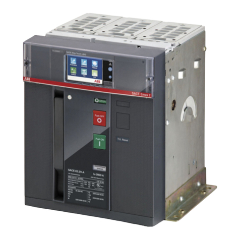
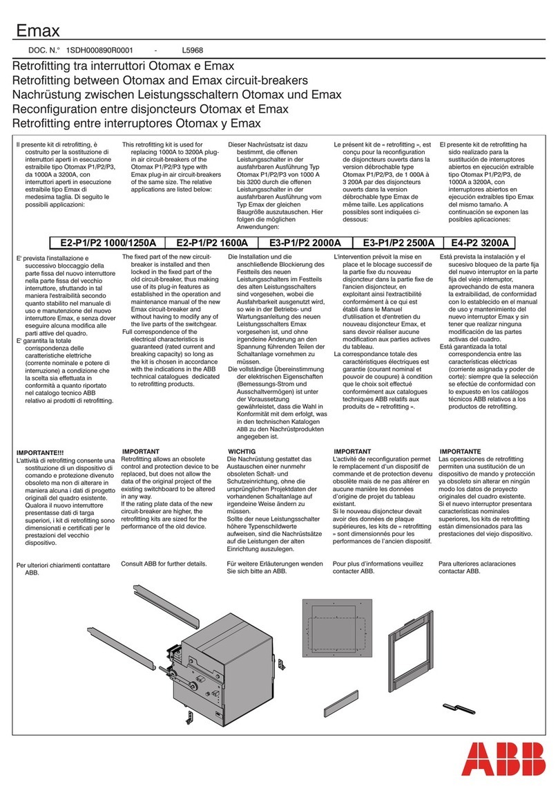
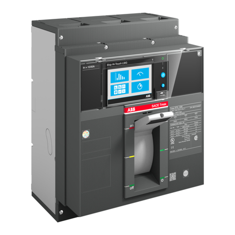
  9. ABB SACE Emax E1 User manual

ABB SACE Emax E1 User manual

L0177 1/16
ABBSACE SACE Emax E1 ÷ E6 601933/625
Interblocco meccanico tra tre interruttori - Tipo B
Mechanicalinterlockacrossthreecircuit-breakers-TYPEB
MechanischeVerriegelung zwischendreiLeistungsschaltern -TYPB
Verrouillage mécanique entre trois disjoncteurs - TYPE B
Enclavamientomecánicoentretres interruptores – TIPO B
3
In aggiunta per ciascun
interruttore fisso
In addition for each fixed
circuit-breaker
Zusätzlich zu jedem festen
leistungsschalter
En plus pour chaque
disjoncteur fixe
Como accesorio para cada
interruptor fijo
x3 x3 x3
x3
x3
x6
x12
x12
x12
x6
x3
x3
x3 x3
x6
x6
x3
x3
x3
x10
x6
x20
x24
x3
x3 x3
x3
x3
x3
x3
1
Esecuzione estraibile
Withdrawable version
AusfahrbareAusführung
Version débrochable sur chariot
Ejecución extraíble
Esecuzione fisso
Fixed version
FesteAusführung
Version fixe
Ejecución fija
2
APERTO
OPEN
AUS-STELLUNG
OUVERT
ABIERTO
BIANCO
WHITE
WEISS
BLANC
BLANCO
Foratura piano di appoggio
Mounting surface drilling
Bohrung Auflagefläche
Perçage plan d'appui
Taladrado de la superficie de apoyo
135
5.31"
100
3,93" 50
1.96"
20/0,78" 210/8.26"
35
1.37" 50
1.96"
40
1.57"
35/1.37"
40
1.57"
38.5
1.51"
10
1.57"
180
7.08"
20
0.78"
73.5
2.89"
L0177601933/625 2/16
ABBSACE SACE Emax E1 ÷ E6
5
4
500÷750 500÷750
1200 max 1200 max
NOTE GENERALI:
-Perinterblocchiorizzontali.farpassareicavisottolepartifisse(vedifig.16),mantenendolostessoschema
di collegamento illustrato per l'interblocco verticale.
-Nelfissareicaviflessibiliagliinterruttoriridurrealminimoilnumerodellecurve (sommacurvemax 360°).
-Assicurarsi che la forma data ai cavi non possa essere modificata dopo la regolazione.
GENERAL REMARKS:
-For horizontal interlocks, pass the cables under the fixed parts (see fig.16), following the same
connection layout shown for the vertical interlock.
-When attaching flexible cables to circuit-breakers, reduce the number of curves as much as
possible (maximum sum of curves 360°).
-Ascertain that the shape given to cables cannot be changed after the adjustment.
ALLGEMEINE HINWEISE:
-Bei waagrechten Verriegelungen die Kabel unter den festen Teilen durchfüren
(siehe Abb.16);hierbei dem Anschlußplan für die vertikalen Verriegelungen folgen.
-Bei der Befestigung der flexiblen Kabel an den Schaltgeräten die Anzahl von Kurven auf ein Minimum
beschränken (Summer der Kurven max. 360°).
-Sicherstellen, daß die den Kabeln gegebene Form nicht nach der Einstellung verändert werden kann.
REMARQUES GENERALES:
-Pour des interverrouillages horizontaux, faire passer les câbles sous les parties fixes (cf.
fig.16),en maintenant le même schéma de raccordement que celui illustré pour
l’interverrouillagevertical.
-Lorsqu’on fixe les câbles flexibles sur les disjoncteurs, réduire au minimum le nombre de
oudes (somme des coudes 360° maxi).
-S’assurer que la forme donnée aux câbles ne peut pas être modifiée après le réglage.
NOTAS GENERALES
-Para enclavamientos horizontales, hacer pasar los cables bajo las partes fijas (ver la fig.16),
manteniendo el mismo esquema de conexión ilustrado para el enclavamiento vertical.
-Al fijar los cables flexibles a los interruptores, reducir al mínimo el número de codos
(suma de codos máx. 360°).
-Asegurarse de que la forma dada a los cables no pueda modificarse después de la regulación.
6
19.7"÷29.5"
19.7"÷29.5"
47.2" max 47.2" max
L0177 3/16
ABBSACE SACE Emax E1 ÷ E6 601933/625
10
9
8
7
2Nm
1,1Nm
L0177601933/625 4/16
ABBSACE SACE Emax E1 ÷ E6
11
N.B.COME SPECIFICATOAPAG.8 e12
Se emergenza in pos. "A" : cavi N°3 e N°6
Se emergenza in pos. "B" : cavi N°1 e N°5
Se emergenza in pos. "C" : cavi N°2 e N°4
NOTE:ASSPECIFIEDON PAGES 8 and12
In case of emergency in pos. "A" : cables 3 and 6
In case of emergency in pos. "B" : cables 1 and 5
In case of emergency in pos. "C" : cables 2 and 4
HINWEIS:WIEANGEGEBENAUFSEITE8und12
Wenn Not-Aus in Pos. "A" : Kabel Nr. 3 und Nr. 6
Wenn Not-Aus in Pos. "B" : Kabel Nr. 1 und Nr. 5
Wenn Not-Aus in Pos. "C" : Kabel Nr. 2 und Nr. 4
N.B.COMMEINDIQUE p.8 et 12
Si urgence en pos. "A" : câbles N° 3 et N° 6
Si urgence en pos. "B" : câbles N° 1 et N° 5
Si urgence en pos. "C" : câbles N° 2 et N° 4
N.B.COMOSEESPECIFICAENLASPÁG.8E12
Si emergencia en pos. "A" : cables Nº 3 y Nº 6
Si emergencia en pos. "B" : cables Nº 1 y Nº 5
Si emergencia en pos. "C" : cables Nº 2 y Nº 4
N° mm mm
1
2
3
4
5
6
2700
2150
2150
2150
2700
2150
3550
2700
2700
2700
3550
2700
N°3
N°1
N°6
N°2
N°4
N°5
30 Max
50±0.5
2Nm
N°
N°
-INTERBLOCCO
VERTICALE
-VERTICAL
INTERLOCK
-VERTIKALE
VERRIEGELUNG
-INTERVERROUILAGE
VERTICAL
-ENCLAVAMIENTO
VERTICAL
-INTERBLOCCO
ORIZZONTALE
-HORIZONTAL
INTERLOCK
-HORIZONTALE
VERRIEGELUNG
-INTERVERROUILAGE
HORIZONTAL
-ENCLAVAMIENTO
HORIZONTAL
Quotadipreregolazione
Presettingdimension
Voreinstellwert
Cotedepréréglage
Cotadeprerregulación
Quotaimportante
Importantmeasurement
WichtigesMaß
Coteimportante
Cotaimportante
L0177 5/16
ABBSACE SACE Emax E1 ÷ E6 601933/625
14
13
12
3,7 Nm
2 Nm
Interruttoreestraibile
Withdrawablecircuit-breaker
AusfahrbarerLeistungsschalter
Disjoncteurdébrochablesurchariot
Interruptorextraíble
L0177601933/625 6/16
ABBSACE SACE Emax E1 ÷ E6
16
15
11Nm
Recuperare il cavo in eccesso spostando verso l'alto questa curva.
Recover the excess cable by shifting this curve to the top.
Zum Verwahren der Kabelüberlänge diese Kurve nach oben verschieben.
Récupérer le câble en excès en déplaçant ce coude vers le haut.
Recobrar el cable en exceso desplazando este codo hacia arriba.
L0177 7/16
ABBSACE SACE Emax E1 ÷ E6 601933/625
17
"C"
5
4
"B"
"A"
45
6
62
2
31
3
1
Sequenza di montaggio cavi consigliata : 1,2,3
Recommended sequence for mounting cables : 1,2,3
Empfohlene Reihenfolge für die Montage der Kabel: 1,2,3
Séquence conseillée de montage des câbles: 1,2,3
Secuencia de montaje de los cables aconsejada: 1, 2, 3
1 2 3
L0177601933/625 8/16
ABBSACE SACE Emax E1 ÷ E6
18
EMERGENZA POS.A
EMERGENCY POS. A
NOT-AUS POS.A
URGENCE POS.A
EMERGENCIA POS. A
"C"
"B"
"A"
5
1
6
331
434 3
6262
1
54
2
45
21
56
EMERGENZA POS.B
EMERGENCY POS. B
NOT-AUS POS.B
URGENCE POS.B
EMERGENCIA POS. B
EMERGENZA POS.C
EMERGENCY POS. C
NOT-AUS POS.C
URGENCE POS.C
EMERGENCIA POS. C
L0177 9/16
ABBSACE SACE Emax E1 ÷ E6 601933/625
21
20
19
3,7 Nm
Terminare il montaggio con le fig. 30 e 31.
Complete assembly with fig. 30 and 31.
Die Montage mit den Abbildungen 30 und 31 beenden.
Terminer le montage avec les fig. 30 et 31.
Terminar el montaje como ilustran las fig. 30 y 31.
L0177601933/625 10/16
ABBSACE SACE Emax E1 ÷ E6
22
2Nm
24
23
9 Nm
Interruttorefisso
Fixedcircuit-breaker
FesterLeistungsschalter
Disjoncteurfixe
Interruptorfijo
L0177 11/16
ABBSACE SACE Emax E1 ÷ E6 601933/625
25
"C"
5
4
"B"
"A"
45
6
62
21
3
31
1 2 3
Sequenza di montaggio cavi consigliata : 1,2,3
Recommended sequence for mounting cables : 1,2,3
Empfohlene Reihenfolge für die Montage der Kabel: 1,2,3
Séquence conseillée de montage des câbles: 1,2,3
Secuencia de montaje de los cables aconsejada: 1, 2, 3
L0177601933/625 12/16
ABBSACE SACE Emax E1 ÷ E6
26
"C"
5
1
4
2
12
45
"B"
"A"
6
3
34
2
4
56
31
3
6
1
5
62
EMERGENZA POS.A
EMERGENCY POS. A
NOT-AUS POS.A
URGENCE POS.A
EMERGENCIA POS. A
EMERGENZA POS.B
EMERGENCY POS. B
NOT-AUS POS.B
URGENCE POS.B
EMERGENCIA POS. B
EMERGENZA POS.C
EMERGENCY POS. C
NOT-AUS POS.C
URGENCE POS.C
EMERGENCIA POS. C
L0177 13/16
ABBSACE SACE Emax E1 ÷ E6 601933/625
29
28
27
3,7 Nm
L0177601933/625 14/16
ABBSACE SACE Emax E1 ÷ E6
REGOLAZIONE:
N.B. NELLE REGOLAZIONI QUANDO SI AGISCE SUI DADI NON FAR RUOTARE SU SE' STESSI I PUNTALI DEI CAVI.
1. INSERIRE LE PARTI MOBILI NELLE PARTI FISSE (SE ESTRAIBILI).
2. CHIUDERE L'INTERRUTTORE "A".
3. 1 TIRARE I DUE TIRANTI "H" DELL'INTERRUTTORE CHIUSO VERSO IL BASSO FINO A PORTARE I DUE TIRANTI "J" DEGLI
INTERRUTTORI APERTI IN LEGGERA BATTUTA SUL PIANO K.
3. 2 MONTARE I DADI "L" E CON LA MANO PORTARLI IN LEGGERA BATTUTA SUL PIANO "M".
3. 3 BLOCCARE CON CHIAVE Ch.8 I DADI "N".
4. APRIRE L'INTERRUTTORE "A".
5. CHIUDERE L'INTERRUTTORE "B" E RIPETERE IL PUNTO 3.
6. APRIRE L'INTERRUTTORE "B".
7. CHIUDERE L'INTERRUTTORE "C" E RIPETERE IL PUNTO 3.
8. APRIRE L'INTERRUTTORE "C".
9. ESEGUIRE ALCUNE MANOVRE DI CHIUSURA E APERTURA, QUINDI VERIFICARE LA BATTUTA DEI TIRANTI "J" SUL PIANO
"K".
10. APRIRE I TRE INTERRUTTORI.
ADJUSTMENT:
NOTE: DURING ADJUSTMENTS, DO NOT ALLOW THE CABLE TERMINALS TO ROTATE WHEN WORKING ON THE NUTS.
1. INSERT THE MOVING PARTS INTO THE FIXED PARTS (IF WITHDRAWABLE) .
2. CLOSE THE CIRCUIT-BREAKER "A".
3. 1 PULL THE TIE-RODS "H" OF THE CLOSED CIRCUIT-BREAKER DOWNWARD AND BRING THE TWO TIE-RODS "J" OF
THE OPEN CIRCUIT-BREAKERS TO TOUCH LIGHTLY AGAINST THE SURFACE "K".
3. 2 MOUNT THE NUTS "L" AND MANUALLY BRING THEM TO TOUCH LIGHTLY AGAINST THE SURFACE "M".
3. 3 TIGHTEN THE NUTS "N" USING AN 8-GAUGE WRENCH.
4. OPEN THE CIRCUIT-BREAKER "A".
5. CLOSE THE CIRCUIT-BREAKER "B" AND REPEAT STEP 3.
6. OPEN THE CIRCUIT-BREAKER "B".
7. CLOSE THE CIRCUIT-BREAKER "C" AND REPEAT STEP 3.
8. OPEN THE CIRCUIT-BREAKER "C".
9. OPEN AND CLOSE A FEW TIMES, THEN MAKE SURE THAT THE TIE-RODS "J" TOUCH LIGHTLY AGAINST THE
SURFACE "K".
10. OPEN THE THREE CIRCUIT-BREAKERS.
"H"
"M"
"N"
"L"
"J"
"K"
2Nm
L0177 15/16
ABBSACE SACE Emax E1 ÷ E6 601933/625
30
EINSTELLUNG:
HINWEIS: BEI DER BETÄTIGUNG DER MUTTERN WÄHREND DER EINSTELLUNG DIE KABELSCHUHE NICHT UM SICH SELBST
DREHEN
1. DIE BEWEGLICHEN TEILE IN DIE FESTEN TEILE EINSETZEN (FALLS AUSFAHRBAR).
2. DEN LEISTUNGSSCHALTER "A"SCHLIESSEN.
3. 1 DIE ZUGSTANGEN "H" DES GESCHLOSSENEN LEISTUNGSSCHALTERS NACH UNTEN ZIEHEN, BIS DIE BEIDEN
ZUGSTANGEN "J" DER GEÖFFNETEN LEISTUNGSSCHALTER LEICHT AN FLÄCHE "K" ANSCHLAGEN.
3. 2 DIE MUTTERN "L" EINSETZEN UND MIT DER HAND LEICHT IN ANSCHLAG AN FLÄCHE "M" BRINGEN.
3. 3 DIE MUTTERN "N" MIT SCHLÜSSEL Ch.8 BLOCKIEREN.
4. LEISTUNGSSCHALTER "A" ÖFFNEN.
5. LEISTUNGSSCHALTER "B" SCHLIESSEN UND SCHRITT 3 WIEDERHOLEN.
6. LEISTUNGSSCHALTER "B" ÖFFNEN.
7. LEISTUNGSSCHALTER "C" SCHLIESSEN UND SCHRITT 3 WIEDERHOLEN.
8. LEISTUNGSSCHALTER "C" ÖFFNEN.
9. EINIGE EIN- UND AUSSCHALTUNGEN VORNEHMEN UND DANN DEN ANSCHLAG DER ZUGSTANGEN "J" AN FLÄCHE
"K" PRÜFEN.
10. DIE DREI LEISTUNGSSCHALTER ÖFFNEN.
REGLAGE:
N.B. LORS DES REGLAGES, QUAND ON AGIT SUR LES ECROUS, NE PAS FAIRE TOURNER LES COSSES DES CABLES SUR
ELLES-MEMES.
1. EMBROCHER LES PARTIES MOBILES DANS LES PARTIES FIXES (SI DEBROCHABLES SUR CHARIOT).
2. FERMER LE DISJONCTEUR "A".
3. 1 TIRER LES DEUX TIRANTS "H" DU DISJ. FERME VERS LE BAS JUSQU’A AMENER LES DEUX TIRANTS "J" DES
DISJONCTEURS OUVERTS LEGEREMENT EN BUTEE CONTRE LE PLAN K.
3. 2 MONTER LES ECROUS "L" ET, A LA MAIN, LES FAIRE LEGEREMENT BUTER CONTRE LE PLAN "M".
3. 3 BLOQUER AVEC UNE CLE N° 8 LES ECROUS "N".
4. OUVRIR LE DISJONCTEUR "A".
5. FERMER LE DISJONCTEUR "B" ET REPETER LE POINT 3.
6. OUVRIR LE DISJONCTEUR "B".
7. FERMER LE DISJONCTEUR "C" ET REPETER LE POINT 3.
8. OUVRIR LE DISJONCTEUR "C".
9. EFFECTUER QUELQUES MANOEUVRES DE FERMETURE ET D’OUVERTURE, PUIS VERIFIER LA BUTEE DES TIRANTS
"J" CONTRE LE PLAN "K".
10. OUVRIR LES TROIS DISJONCTEURS.
REGULACIÓN:
N.B. DURANTE LAS REGULACIONES, CUANDO SE HACEN GIRAR LAS TUERCAS, IMPEDIR QUE LOS TERMINALES DE LOS
CABLES GIREN SOBRE SÍ MISMOS.
1. INSERTAR LAS PARTES MÓVILES EN LAS FIJAS (SI SON EXTRAÍBLES).
2. CERRAR EL INTERRUPTOR "A".
3. 1 LLEVAR LOS DOS TIRANTES "H" DEL INTERRUPTOR CERRADO HACIA ABAJO, HASTA QUE LOS DOS
TIRANTES "J" DE LOS INTERRUPTORES ABIERTOS SE APOYEN LIGERAMENTE EN LA SUPERFICIE "K".
3. 2 MONTAR LAS TUERCAS "L" Y APOYARLAS LIGERAMENTE, CON LA MANO, EN LA SUPERFICIE "M".
3. 3 BLOQUEAR LAS TUERCAS "N" CON LA LLAVE DE 8.
4. ABRIR EL INTERRUPTOR "A".
5. CERRAR EL INTERRUPTOR "B" Y REPETIR EL PUNTO 3.
6. ABRIR EL INTERRUPTOR "B".
7. CERRAR EL INTERRUPTOR "C" Y REPETIR EL PUNTO 3.
8. ABRIR EL INTERRUPTOR "C".
9. EFECTUAR ALGUNAS MANIOBRAS DE CIERRE Y APERTURA, Y VERIFICAR QUE LOS TIRANTES "J" SE APOYEN EN
LA SUPERFICIE "K".
10. ABRIR LOS TRES INTERRUPTORES.
L0177601933/625 16/16
ABBSACE SACE Emax E1 ÷ E6
31
Head Office: Via Baioni, 35 - 24123 Bergamo - Italy - Tel.: +39 (0) 35 395111 - Telex: 301627 ABBSAC I - Telefax: +39 (0) 35 395306-395433
CONTROLLO MECCANICO
RIARMARE LE MOLLE DEI COMANDI DEGLI INTERRUTTORI ED ESEGUIRE LE SEGUENTI OPERAZIONI:.
1. CHIUDERE L'INTERRUTTORE "EMERGENZA" E CONTROLLARE CHE GLI INTERRUTTORI "LINEA 1" E "LINEA 2"
NON POSSANO ESSERE CHIUSI. APRIRE L'INTERRUTTORE "EMERGENZA" E RIARMARE LE MOLLE DEL COMANDO.
2. CHIUDERE L'INTERRUTTORE "LINEA 1" E CONTROLLARE CHE L'INTERRUTTORE "EMERGENZA" NON POSSA ESSERE
CHIUSO. APRIRE L'INTERRUTTORE "LINEA 1" E RIARMARE LE MOLLE DEL COMANDO.
3. CHIUDERE L'INTERRUTTORE "LINEA 2" E CONTROLLARE CHE L'INTERRUTTORE "EMERGENZA" NON POSSA ESSERE
CHIUSO. APRIRE L'INTERRUTTORE "LINEA 2" E RIARMARE LE MOLLE DEL COMANDO.
MECHANICAL CHECK
RESET THE CIRCUIT-BREAKERS OPERATING MECHANISM SPRINGS AND PERFORM THE FOLLOWING OPERATIONS:
1. CLOSE THE "EMERGENCY" CIRCUIT-BREAKER AND MAKE SURE THAT THE "LINE 1" AND "LINE 2" CIRCUIT-
BREAKERS CANNOT BE CLOSED. OPEN THE "EMERGENCY" CIRCUIT-BREAKER AND RESET THE OPERATING
MECHANISM SPRINGS.
2. CLOSE THE "LINE 1" CIRCUIT-BREAKER AND MAKE SURE THAT THE "EMERGENCY" CIRCUIT-BREAKER CANNOT BE
CLOSED. OPEN THE "LINE 1" CIRCUIT-BREAKER AND RESET THE OPERATING MECHANISM SPRINGS.
3. CLOSE THE "LINE 2" CIRCUIT-BREAKER AND MAKE SURE THAT THE "EMERGENCY" CIRCUIT-BREAKER CANNOT BE
CLOSED. OPEN THE "LINE 2" CIRCUIT-BREAKER AND RESET THE OPERATING MECHANISM SPRINGS.
MECHANISCHE KONTROLLE
DIE FEDERN DER ANTRIEBE DER LEISTUNGSSCHALTER WIEDER SPANNEN UND FOLGENDE SCHALTUNGEN AUSFÜHREN:
1. DEN LEISTUNGSSCHALTER "NOT-AUS" SCHLIESSEN UND SICHERSTELLEN, DASS DIE LEISTUNGSSCHALTER
"LINIE 1" UND "LINIE 2" NICHT GESCHLOSSEN WERDEN KÖNNEN. LEISTUNGSSCHALTER "NOT-AUS" ÖFFNEN UND
DIE FEDERN SEINES ANTRIEBS SPANNEN.
2. LEISTUNGSSCHALTER "LINIE 1" SCHLIESSEN UND SICHERSTELLEN, DASS LEISTUNGSSCHALTER "NOT-AUS"
NICHT GESCHLOSSEN WERDEN KANN. LEISTUNGSSCHALTER "LINIE 1" ÖFFNEN UND DIE FEDERN SEINES ANTRIEBS
SPANNEN.
3. LEISTUNGSSCHALTER "LINIE 2" SCHLIESSEN UND SICHERSTELLEN, DASS LEISTUNGSSCHALTER "NOT-AUS"
NICHT GESCHLOSSEN WERDEN KANN. LEISTUNGSSCHALTER "LINIE 2" ÖFFNEN UND DIE FEDERN SEINES
ANTRIEBS SPANNEN.
CONTROLE MECANIQUE
REARMER LES RESSORTS DES COMMANDES DES DISJONCTEURS ET EFFECTUER LES OPERATIONS SUIVANTES:
1. FERMER LE DISJONCTEUR "URGENCE" ET CONTROLER QUE LES DISJONCTEURS "LIGNE 1" ET "LIGNE 2"
NE PEUVENT PAS ETRE FERMES. OUVRIR LE DISJONCTEUR "URGENCE" ET REARMER LES RESSORTS DE LA
COMMANDE.
2. FERMER LE DISJONCTEUR "LIGNE 1" ET CONTROLER QUE LE DISJONCTEUR "URGENCE" NE PEUT PAS ETRE
FERME. OUVRIR LE DISJONCTEUR "LIGNE 1" ET REARMER LES RESSORTS DE LA COMMANDE.
3. FERMER LE DISJONCTEUR "LIGNE 2" ET CONTROLER QUE LE DISJONCTEUR "URGENCE" NE PEUT PAS ETRE
FERME. OUVRIR LE DISJONCTEUR "LIGNE 2" ET REARMER LES RESSORTS DE LA COMMANDE.
CONTROL MECÁNICO
RESTABLECER LOS RESORTES DE LOS MANDOS DE LOS INTERRUPTORES Y EFECTUAR LAS SIGUIENTES OPERACIONES:
1. CERRAR EL INTERRUPTOR "EMERGENCIA" Y CONTROLAR QUE LOS INTERRUPTORES "LÍNEA 1" Y "LÍNEA 2" NO
PUEDAN CERRARSE. ABRIR EL INTERRUPTOR "EMERGENCIA" Y RESTABLECER LOS RESORTES DEL MANDO.
2. CERRAR EL INTERRUPTOR "LÍNEA 1" Y CONTROLAR CHE EL INTERRUPTOR "EMERGENCIA" NO PUEDA
CERRARSE. ABRIR EL INTERRUPTOR “LÍNEA 1” Y RESTABLECER LOS RESORTES DEL MANDO.
3. CERRAR EL INTERRUPTOR "LÍNEA 2" Y CONTROLAR CHE EL INTERRUPTOR "EMERGENCIA" NO PUEDA
CERRARSE. ABRIR EL INTERRUPTOR "LÍNEA 2" Y RESTABLECER LOS RESORTES DEL MANDO.

Other manuals for SACE Emax E1

5

This manual suits for next models

1

Other ABB Circuit Breaker manuals

ABB F204 125 Series User manual

ABB

ABB F204 125 Series User manual

ABB Mechanism HMB-8 User manual

ABB

ABB Mechanism HMB-8 User manual

ABB SACE Emax 2 User manual

ABB

ABB SACE Emax 2 User manual

ABB GE Power Break II User manual

ABB

ABB GE Power Break II User manual

ABB AKD6-800A User manual

ABB

ABB AKD6-800A User manual
ABB H569-445 User manual

ABB

ABB H569-445 User manual

ABB SACE Emax 2 E2.2 Installation instructions

ABB

ABB SACE Emax 2 E2.2 Installation instructions

ABB VM1 User manual

ABB

ABB VM1 User manual

ABB VD4 Series Installation and operating instructions

ABB

ABB VD4 Series Installation and operating instructions

ABB Record Plus FB100 User manual

ABB

ABB Record Plus FB100 User manual

ABB SACE Emax 2 E2.2 User manual

ABB

ABB SACE Emax 2 E2.2 User manual

ABB SACE Emax E1 User manual

ABB

ABB SACE Emax E1 User manual

ABB ADVAC 03 Installation and operating instructions

ABB

ABB ADVAC 03 Installation and operating instructions

ABB eVD4 Quick guide

ABB

ABB eVD4 Quick guide

ABB Vmax User manual

ABB

ABB Vmax User manual

ABB SACE Tmax XT User manual

ABB

ABB SACE Tmax XT User manual
ABB HD4-HPA Series Quick guide

ABB

ABB HD4-HPA Series Quick guide

ABB SACE Emax 2 Product manual

ABB

ABB SACE Emax 2 Product manual

ABB Emax User manual

ABB

ABB Emax User manual

ABB AMVAC User manual

ABB

ABB AMVAC User manual

ABB ADVAC Installation and operating instructions

ABB

ABB ADVAC Installation and operating instructions

ABB Emax X1 UL User manual

ABB

ABB Emax X1 UL User manual

ABB T7-T7M-X1 User guide

ABB

ABB T7-T7M-X1 User guide

ABB DEH41820 User manual

ABB

ABB DEH41820 User manual

Popular Circuit Breaker manuals by other brands

Allen-Bradley 140G-R Series Getting started

Allen-Bradley

Allen-Bradley 140G-R Series Getting started

IEK AR-AUX-UR-220 Operation manual

IEK

IEK AR-AUX-UR-220 Operation manual

Cutler-Hammer W-VAC Instructions for installation, operation and maintenance

Cutler-Hammer

Cutler-Hammer W-VAC Instructions for installation, operation and maintenance

Mitsubishi Electric V Series manual

Mitsubishi Electric

Mitsubishi Electric V Series manual

Eaton IZM-KLP-SO-RONIS manual

Eaton

Eaton IZM-KLP-SO-RONIS manual

Siemens 3VT9100-8CE00 operating instructions

Siemens

Siemens 3VT9100-8CE00 operating instructions

Eaton Power Defense PDC9-ETU Installation

Eaton

Eaton Power Defense PDC9-ETU Installation

WEG DWB800 installation instructions

WEG

WEG DWB800 installation instructions

Eaton W-VACi user manual

Eaton

Eaton W-VACi user manual

Siemens 5WG1140-1AB13 quick start guide

Siemens

Siemens 5WG1140-1AB13 quick start guide

Eaton Series NRX Instruction leaflet

Eaton

Eaton Series NRX Instruction leaflet

KING HP30 Series quick start guide

KING

KING HP30 Series quick start guide

Siemens SENTRON VL Series System manual

Siemens

Siemens SENTRON VL Series System manual

TERASAKI TemBreak 2 E125 instruction manual

TERASAKI

TERASAKI TemBreak 2 E125 instruction manual

Tracon Electric TGV3 user manual

Tracon Electric

Tracon Electric TGV3 user manual

Westinghouse DB-75 instructions

Westinghouse

Westinghouse DB-75 instructions

Allen-Bradley 140G-K-EA1R1B Installation

Allen-Bradley

Allen-Bradley 140G-K-EA1R1B Installation

Schrack LSD3 Series operating instructions

Schrack

Schrack LSD3 Series operating instructions

manuals.online logo
manuals.online logoBrands
  • About & Mission
  • Contact us
  • Privacy Policy
  • Terms and Conditions

Copyright 2025 Manuals.Online. All Rights Reserved.