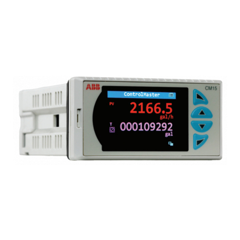
ABB C320 User manual

Booster Pump Controller
C320
User Guide
IM/C320_6

ABB
EN ISO 9001:2000
Cert. No. Q5907
The Company
We are an established world force in the design and manufacture of
instrumentation for industrial process control, flow measurement, gas and
liquid analysis and environmental applications.
As a part of ABB, a world leader in process automation technology, we offer
customers application expertise, service and support worldwide.
We are committed to teamwork, high quality manufacturing, advanced
technology and unrivalled service and support.
The quality, accuracy and performance of the Company’s products result
from over 100 years experience, combined with a continuous program of
innovative design and development to incorporate the latest technology.
The UKAS Calibration Laboratory No. 0255 is just one of the ten flow
calibration plants operated by the Company, and is indicative of our
dedication to quality and accuracy.
EN 29001 (ISO 9001)
Lenno, Italy – Cert. No. 9/90A
R
E
G
I
S
T
E
R
E
D
Health and Safety
To ensure that our products are safe and without risk to health, the following points must be noted:
1. The relevant sections of these instructions must be read carefully before proceeding.
2. Warning labels on containers and packages must be observed.
3. Installation, operation, maintenance and servicing must only be carried out by suitably trained personnel and
in accordance with the information given.
4. Normal safety precautions must be taken to avoid the possibility of an accident occurring when operating in
conditions of high pressure and/or temperature.
5. Chemicals must be stored away from heat, protected from temperature extremes and powders kept dry.
Normal safe handling procedures must be used.
6. When disposing of chemicals ensure that no two chemicals are mixed.
Safety advice concerning the use of the equipment described in this manual or any relevant hazard data sheets
(where applicable) may be obtained from the Company address on the back cover, together with servicing and
spares information.
Electrical Safety
This equipment complies with the requirements of CEI/IEC 61010-1:2001-2 'Safety Requirements for Electrical
Equipment for Measurement, Control and Laboratory Use'. If the equipment is used in a manner NOT specified by
the Company, the protection provided by the equipment may be impaired.
Symbols
One or more of the following symbols may appear on the equipment labelling:
Information in this manual is intended only to assist our customers in the efficient operation of our equipment. Use
of this manual for any other purpose is specifically prohibited and its contents are not to be reproduced in full or part
without prior approval of the Technical Communications Department.
Warning – Refer to the manual for instructions
Caution – Risk of electric shock
Protective earth (ground) terminal
Earth (ground) terminal
Direct current supply only
Alternating current supply only
Both direct and alternating current supply
The equipment is protected
through double insulation

1
The COMMANDER 320 Booster Pump Controller acts as a differential pressure switch for use
in the regeneration section of a pasteurizer. If the difference between pasteurized milk
pressure and raw milk pressure falls below a preset level, the controller shuts down the raw
milk booster pump or alternatively, channels the pasteurized milk into the divert flow.
The COMMANDER 320 has the following features:
• Two 4 to 20mA analog inputs.
• A transmitter power supply capable of powering the raw and pasteurized 2-wire
pressure transmitters.
• A digital display of the raw and pasteurized product pressures.
• A bargraph display of the difference between the raw and pasteurized pressures.
• A deviation alarm to detect when the difference between the raw and pasteurized
pressures falls below a preset minimum.
• A start-up alarm which allows the booster pump to remain off until the normal system
operating back pressure is achieved.
• A manual override facility which allows the booster pump to be turned off using a digital input.
• Selectable pressure differential retransmission output.
• Three relay outputs: two for booster pump or divert valve control, one to operate a
warning light or horn.
This manual is divided into 4 sections and contains all the information necessary to install,
configure and operate the instrument.
GETTING STARTED
Symbol Identification and Contents of Sections
Displays and Function Keys
• Displays and function keys
• LED Indication
• Error Messages
Operating Level
• Operating Page
• Operating Page Messages
• Alarm Acknowledge Page
• Security Access
Configuration Level
• Set Up Alarms
• Set Up Inputs
• Set Up Display
• Scale Adjustment
• Security Code Set Up
• Commissioning
Installation
• Siting
• Mounting
• Electrical connections

2
Section Page
CONTENTS
1 DISPLAYS AND CONTROLS ............................................................................. 3
1.1 Introduction .................................................................................................................3
1.2 Use of Controls ...........................................................................................................3
1.3 Displays and LED Indicators ....................................................................................... 4
1.3.1 LED Indications, Relay and Alarm States ........................................................ 4
1.3.2 Deviation Bargraph .......................................................................................... 5
1.4 Instrument Power-up ................................................................................................... 5
2 OPERATING LEVEL........................................................................................... 6
2.1 Operating Page ........................................................................................................... 6
2.2 Operating Page Messages .........................................................................................6
2.3 Alarm Acknowledge Page ...........................................................................................6
2.4 Security Access ..........................................................................................................7
2.4.1 Security Code Page .........................................................................................8
3 CONFIGURATION LEVEL.................................................................................. 9
3.1 Preparation for Changes to the Parameters ...............................................................9
3.2 Set Up Alarms Page .................................................................................................10
3.3 Set Up Inputs ............................................................................................................12
3.4 Set Up Display Page .................................................................................................14
3.5 Retransmission Output Page ....................................................................................15
3.6 Scale Adjustment Page .............................................................................................16
3.7 Access Page .............................................................................................................18
3.8 Commissioning .........................................................................................................19
4 INSTALLATION ................................................................................................ 20
4.1 Checking the Code Number ......................................................................................20
4.2 Siting .........................................................................................................................21
4.3 Mounting ...................................................................................................................22
4.4 Access to Terminals .................................................................................................. 23
4.5 Setting the Input Selector Links ................................................................................24
4.6 Setting the Isolated Output Link ................................................................................24
4.7 Cable Glands and Conduit Fixings ...........................................................................25
4.7.1 Cable Glands (IEC – 20mm) ..........................................................................25
4.7.2 Conduit Adaptors (N. American – 0.5in) ........................................................25
4.7.3 Cable Glands (N. American – 0.5in) ..............................................................26
4.8 Connections Summary .............................................................................................. 27
4.9 Input Connections ..................................................................................................... 29
4.9.1 Current Input .................................................................................................. 29
4.9.2 2-wire Transmitter .......................................................................................... 29
4.10 Output Connections ................................................................................................29
4.11 Logic Input Connection ...........................................................................................29
4.12 Relay Connections .................................................................................................. 30
4.13 Power Supply Selection and AC Connections ........................................................ 31
SPECIFICATION .................................................................................................... 32
3
1.1 Introduction – Fig. 1.1
The Commander 320 front panel display, function keys and LED indicators are shown in
Fig. 1.1
Note. Continued pressure on the
and switches causes the
rate of change of the displayed
value to increase. To make small
adjustments operate the switches
momentarily.
Frame 1
Frame 2
Frame 3
Frame 4
Page 1
Frame 1
Frame 2
Frame 3
Page 2
Frame 1
Frame 2
Frame 3
Page X
Frame 4
Advance to
next Frame
Adjust
Parameter Value
Parameter X
Y
Z
Select
Used to acknowledge alarm A1 and de-energise relay 3
Fig. 1.2 Advancing to Next Page
Fig. 1.3 Moving between Frames
Fig. 1.4 Adjusting a Parameter Value
Fig. 1.5 Selecting a Parameter Choice
Fig. 1.6 Alarm Acknowledge Switch
1.2 Use of Controls – Figs. 1.2 to 1.6
1 DISPLAYS AND CONTROLS
Fig. 1.1 Front Panel Display, Function Keys and LED Indicators
'Enter' Switch LED
Deviation Bar
Graph Display
LED Indicators
Controls – Refer to
Figs. 1.2 to 1.6
Displays
RAW
PAS
A1 A2 BP2BP1
'Data Entry' Switch
(use to enter settings
and values in frames)

4
1.3 Displays and LED Indicators
The displays, LED indicators and operation/programming controls are located on the faceplate
on the front of the instrument. The displays comprise 2 rows of 6 characters.
…1 DISPLAYS AND CONTROLS
Table 1.2 LED Indications and Alarm States
Display ConditionAlarm/Relay State
A1 Active and ackd.
A1 Active and unackd.
A1 Inactive
A2 Active
A2 Inactive
Relay 1 De-energised
Relay 1 Energised
Relay 2 De-energised
Relay 2 Energised
Relay 3 Energised
Relay 3 De-energised
Pasteurized I/P pressure:
< Raw I/P pressure + divert trip level
Pasteurized I/P pressure:
≥Raw I/P pressure + divert trip level
Displayed on power up.
Active until Pasteurized I/P pressure
≥Start up trip level then remains inactive until
power is switched off and on.
Either A1 or A2 active
A1 and A2 inactive
A1 active
A1 inactive.
A1 active and unacknowledged.
A1 acknowledged.
On
Flashing
Off
On
Off
Off
On
Off
On
On
Off
LED
A1
A2
BP1
BP2
1.3.1 LED Indications, Relay and Alarm States
LED indications, relay and alarm states are shown in Table 1.2. For electrical connections –
see section 4.12.
A
b
C or c
d
E
F
G
H or h
I
J
K
L
M
N or n
O or o
P
Q
r
S
t
U
V
Y
A
B
C
D
E
F
G
H
I
J
K
L
M
N
O
P
Q
R
S
T
U
V
Y
Table 1.1 Character Set

5
1 DISPLAYS AND CONTROLS…
1.3.2 Deviation Bargraph – Fig. 1.7
The deviation bargraph displays:
a) The difference between the raw pressure and pasteurized pressure inputs.
b) The deviation alarm trip value
1.4 Instrument Power-up – Fig. 1.8
Caution. Ensure all connections, including the earth stud, are made correctly.
a) Check that the input sensors are installed correctly.
b) Switch on the supply to the instrument, any power-operated control circuits and the input
signals.
c) The start-up sequence shown in Fig. 1.8 is displayed when the supply is first switched on.
Fig. 1.7 Deviation Bargraph
Deviation alarm trip value
Difference between raw and pasteurized input
pressures is less than the alarm trip value
Difference between raw and pasteurized input
pressures is greater than the alarm trip value
Note. Acknowledging error clears the error but does not rectify the fault, check the
configuration.
Instrument Test identifies the instrument type, C320 – see
Table 4.1
Flashing
between
Normal Display
C320
tESt
A1 BP2A2 BP1
RAW
PAS
A1 A2
100.3
200.5
BP2BP1
RAW
PAS
A1 A2
CONFIG
CHECK
BP2BP1
RAW
PAS
Configuration Check
indicates configuration error,
acknowledged by pressing
the switch.
Fig. 1.8 Instrument Displays at Power-up

6
Operating Page
Pressure of raw product.
Pressure of pasteurized product.
If the difference between the two values falls below the
required level, i.e. Alarm 1 becomes Active, both values flash
ON and OFF.
2 OPERATING LEVEL
2.1 Operating Page
Information. The instrument has a dedicated Operating page. This page is used for general
monitoring of the process measurements and is not affected by the security system which
inhibits access to the alarm set up and programming pages – see section 3
5.00
10.00
2.2 Operating Page Messages
Table 2.1 Input Error Messages Displayed in the Operating Page
Reason
Failed Input – raw pressure input failure.
Failed Input – pasturized pressure input failure.
Message
F-INPt
F-INPt
Page Header – Acknowledge Alarms
Upper Display
Shows the alarm identity and type when an alarm condition is
present.
dEV-AL – deviation alarm A1
SU-AL – start up alarm A2
Lower Display
Shows the trip level of the alarm identified in the upper display.
When the alarm is acknowledged ( pressed ), ACKNGd is
displayed.
Note. If alarm A2 is active, SU-ALis displayed, but the alarm
cannot be acknowledged.
Return to top of page.
2.3 Alarm Acknowledge Page
ACKNLG
ALArMS
dEV-AL
100.5
ACKNGd
dEV-AL

7
2 OPERATING LEVEL…
2.4 Security Access – Figs 2.1 and 2.2
A security system is used to prevent tampering with the program parameters by utilizing a
security input together with an Alarm password and a Configuration password – see Figs. 2.1
and 2.2. Two levels of security are provided:
a) Security input secure – Alarm and configuration settings cannot be accessed.
The security input may be protected by a tamper-proof seal – see Fig.2.3
b) Security input insecure – Alarm and configuration settings can be accessed by use of
the correct password.
Operating
Page
(Section 2.1)
Alarm Acknowledge
Page
(Section 2.3)
Security Code
Page
(Section 2.4)
Security Link
INSECURE +
configuration
security code
Security Link SECURE
Set Up Alarms
Page
(Section 3.2)
Configuration Level –
see Section 3
SEtUP
ALArMS
SECOdE
PAGE
100.3
110.5
ACKNLG
ALArMS
Security Link
INSECURE +
alarm or
configuration
security code
Fig. 2.1 Security Access
Fig. 2.2 Security Settings
No security override on
terminals 31 and 32
323130
Secure
Security override on
terminals 31 and 32
323130
Insecure
Fig. 2.3 Tamper-proof Seal

8
2.4.1 Security Code Page
Page Header – Security Code Page
Set the correct Alarm or Configuration password using the
and switches and press the switch to enter the
code.
The passwords are programmed in the Access Page – see
Section 3.7.
Software version
The Upper display indicates the EPROM series.
The lower display indicates the version number.
Return to top of page
.
…2 OPERATING LEVEL
SECOdE
VEr 2
2001
0

9
3 CONFIGURATION LEVEL
Operating
Page
Section 2.1
SEtUP
ALArMS
COMMIM
SSION
SECOdE
PAGE
100.3
110.5
ACKNLG
ALArMS
SEtUP
INPUt
dISPLY
PAGE
SCALE
AdJUSt
ACCESS
PAGE
Alarm Acknowledge
Page
Section 2.3
Security code
Page
Section 2.4
Set Up Alarms
Page
Section 3.2
Set Up Inputs
Page
Section 3.3
Display
Page
Section 3.4
Scale Adjust
Page
Section 3.6
Access
Page
Section 3.7
Commissioning
Page
Section 3.8
Alarm Identities
■
Trip Levels
Hysteresis
■
■
■
Broken Sensor
Protection Drive
Fault Detection
Level % PV I/P
■
■
Programmable
Filter
Mains Filter
■
Display High/Low
Limits
■
Decimal Point
Bar Graph %
Increment Per Bar
■
■
Scale Adjust raw
Input Range
High/Low Limits
■
Scale Adjust
Pasteurized Range
High/Low Limits
■
Alarm Password
■
■
Configuration
Password
Operating Level
■
Isolated
Retransmission
rEtrAN
OUtPUt
Retransmission
Output Page
Section 3.5
Isolated and non-
isolated output
sources
■
Pressure
difference
retransmission
range
■
Fig. 3.1 Configuration Level Overview
3.1 Preparation for Changes to the Parameters
Ensure that the external alarm/control circuits are isolated if inadvertent operation during
programming is undesirable.
Any change to the operating parameters are implemented using the or switches – see
Section 2.
Note. The instrument responds instantly to parameter changes which are saved when the
switch is pressed.

10
…3 CONFIGURATION LEVEL
3.2 Set Up Alarms Page
Information.
• Two alarms – identified A1 and A2 .
• Adjustable hysteresis value to prevent oscillation of alarm state.
Pasteurized pressure
input
Divert Hysteresis
Value
Alarm On
Alarm Off
Raw pressure
input
Divert trip
level
+
Pasteurized
pressure input
Alarm On
Alarm Off
Start Up
trip level
Fig. 3.2 Deviation Alarm A1
Information. From power up the alarm remains ACTIVE until the trip
value is exceeded. The alarm then remains OFF until the controller is
powered down and up again.
Fig. 3.3 Start Up Alarm A2

11
3 CONFIGURATION LEVEL…
…3.2 Set Up Alarms Page
Page Header – Set Up Alarms.
Divert Trip Level
Set the trip level for alarm A1 in engineering units.
Note.
When alarm A1 is active, relays 1 and 2 are de-energised.
Alarm A1 can be acknowledged by the operator.
When A1 is active and unacknowledged relay 3 is
energised.
When A1 is acknowledged relay 3 is de-energised.
Divert Hysteresis Level
Set the hysteresis level for alarm A1 in engineering units.
Start Up Trip Level
Set the trip level for alarm A2 in engineering units.
Note.
When alarm A2 is active, relay 1 is de-energised.
Alarm A2 cannot be acknowledged by the operator.
Return to top of page.
SEtUP
ALArMS
––––
dVtrIP
––––
dVHYSt
––––
SVtrIP

12
…3 CONFIGURATION LEVEL
3.3 Set Up Inputs – Fig. 3.4
Information.
• All changes made apply to both the raw and pasteurized pressure inputs.
• Both inputs are fixed, 4 to 20mA
• Programmable fault levels and actions.
• Digital filter reduces the effect of noise on inputs.
Example – mA input, range 0 to 100 with 10% fault detection levels.
Current
110
–10
Input Type Display Range
Fault
Detection
Level 10 %
100
0
Fault
Detection
Level 10 %
Display Range
High
Display Range
Low
Programme
Filter
Value set to 0
Value set low
Value set high
Fig. 3.4 Setting Up the Input

13
3 CONFIGURATION LEVEL…
…3.3 Set Up Input Page
Page Header – Set Up Process Variable Input.
Broken Sensor Protection Drive
In the event of a fault being detected on the input, the
displayed value is driven in the direction of the mode
selected.
Select the broken sensor drive required:
NONE – No drive
UP – Upscale drive
dN – Downscale drive.
Note. When a broken input sensor is detected, the unit
switches to Divert Mode and turns the booster pump OFF.
Fault Detection Level Percentage,
A fault level percentage can be set to detect a deviation
above or below the display limits, e.g. If set at 10.0%, then
if an input goes more than 10% above full scale value or
more than 10% below zero value, a fault is detected.
On some ranges the input circuitry may saturate before the
fault level set is reached. In this case an error is detected at
a level below that which is set.
Set the value required, between 0.0 and 100.0% in 0.1%
increments.
Programmable Filter
This filters the pressure inputs, i.e. if the input is stepped,
it smooths the transition between steps and may also be
used for some degree of cleaning of noisy inputs. The filter
time represents the time a step in the input takes to change
the displayed value from 10 to 90% of the step.
Set value required, between 0 and 60 in 1 second
increments.
Mains Filter
Set the frequency of the mains supply used (50 or 60Hz).
Return to top of page.
bSPd
UP
dN
NONE
SEtUP
INPUt
FdLP
10.0
PrGFLt
0
FILtEr
- -Hrt

14
…3 CONFIGURATION LEVEL
3.4 Set Up Display Page
Information.
• Set up engineering ranges and units.
• Programmable increments on deviation bargraph.
• Adjust display brightness.
Page header – Display Page.
Display Full Scale
Set the display value which represents the maximum
pressure input signal, between –9999 and +9999.
Example – For an input range of 4 to 20mA representing a
pressure range of 0.0 to 20.0 psi,, set 200. The decimal
point position is set at the next parameter.
Decimal Point Position
Set the required number of decimal places for both the
display full scale and display zero values. In the example
shown above, set the decimal point position to show
increments of 0.1 psi, i.e. 200.0.
Display Zero
Set the display value which represents the minimum
pressure input signal, between –9999 and +9999.
In the example shown above, set 0.0. The decimal point
position is set automatically.
Increment Per Bar (Bargraph)
This frame sets the deviation from the deviation alarm trip
value that each bar of the Deviation Bargraph represents.
Set the value required, in engineering units.
The decimal point position is set automatically
Brightness Adjustment
Select the required display brightness between 4 and 7.
Return to top of page.
brIGHt
7
dISPLY
PAGE
dIS–HI
1000
dEC–Pt
1000
dIS–LO
0
INCMNt
1

15
3 CONFIGURATION LEVEL…
3.5 Retransmission Output Page
Information.
• Retransmission types – allows retransmission of any two signals, i.e. raw product
pressure, pasteurised product pressure, pressure difference.
• Adjustable pressure difference output range.
• 4 to 20mA outputs.
Page header – Retransmission Output Page.
Retransmission Types
Select the retransmission signals required.
Pressure Difference Output High Value
Set the level of pressure difference at which 20mA output
is required (see Note).
Set the value in engineering units between –9999 and
9999 (the decimal point position is set automatically).
Pressure Difference Output Low Value
Set the level of pressure difference at which 4mA output is
required (see Note).
Set the value in engineering units between –9999 and
9999 (the decimal point position is set automatically).
Note. The pressure difference is calculated as:
pasteurized product pressure – raw product pressure.
Therefore, a positive value = pasteurized product pressure
> raw product pressure.
A negative value = raw product pressure > pasteurized
product pressure.
Return to top of page.
r–d
rEtrAN
OUtPUt
diFFHI
––––
diFFLO
tYPE
d–P
r–P
––––
r–P
r–d
d– P
epyTP/Odetalosi-noNP/OdetalosI
91egapees)ON(degnahcretnitonstuptuO
d–rerusserPtcudorPwaR erusserPdetaluclaC
ecnereffiD
P–d erusserPdetaluclaC
ecnereffiD
tcudorPdeziruetsaP
erusserP
P–rerusserPtcudorPwaR tcudorPdezirue
tsaP
erusserP
91egapees)SEY(degnahcretnistuptuO
d–r erusserPdetaluclaC
ecnereffiD erusserPtcudorPwaR
P–d tcud
orPdeziruetsaP
erusserP
erusserPdetaluclaC
ecnereffiD
P–r tcudorPdeziruetsaP
erusserP erusserPtcudorPwaR

16
…3 CONFIGURATION LEVEL
3.6 Scale Adjustment Page
Information.
• Scale Adjustment Reset – removes any previously programmed offset or scale
adjustment settings.
• System offset errors – can be removed using Offset Adjustment.
• System scale errors – can be removed using Span Adjustment.
• Offset/Span Adjustment – can be used to perform spot calibration.
Switch off the power supply. Connect accurate signal sources, suitable for simulation over the
entire input ranges, in place of the raw product process connections (terminals 13 and 14) and
pasteurized product process connections (terminals 16 and 17).
As a general rule, spot calibration values should be:
< 50% of range span value when using Offset Adjustment parameters.
> 50% of range span value when using Span Adjustment parameters.
Page header – Scale Adjustment
Raw Input Scale Adjustment Reset
Set YES and press to reset the process variable offset
and span values to their nominal values. dONE is displayed
to indicate that these parameters have been reset.
Raw Input Offset Adjustment
Apply the correct input for the spot calibration required.
Note. The displayed units are engineering units.
Set the value required. The decimal point position is set
automatically.
Example – If the display range is 0.0 to 20.0 and a spot
calibration is required at 5.0 and 15.0, inject a signal
equivalent to 5.0 and set the display to 5.0.
Raw Input Span Adjustment
Proceed as for Raw Input Offset Adjustment and apply the
correct input for the spot calibration required. Engineering
units are displayed.
Set the value required. The decimal point position is set
automatically.
For the Example above inject a signal equivalent to 15.0
and set the display to 15.0.
Continued on next page.
SCALE
r–rSt
AdJUSt
no
––––
r–OFS
––––
r–SPN

17
3 CONFIGURATION LEVEL…
…3.6 Scale Adjustment Page
Pasteurized Input Scale Adjustment Reset
Select YES and press to reset the process variable
offset and span values to their nominal values. dONE is
displayed to indicate that these parameters have been
reset.
Pasteurized Input Offset Adjustment
Apply the correct input for the spot calibration required.
Note. The displayed units are engineering units.
Set the value required. The decimal point position is set
automatically.
Example – If the display range is 0.0 to 20.0 and a spot
calibration is required at 5.0 and 15.0 inject a signal
equivalent to 5.0 and set the display to 5.0.
Pasteurized Input Span Adjustment
Proceed as for Raw Input Offset Adjustment and apply the
correct input for the spot calibration required. Engineering
units are displayed.
Set the value required. The decimal point position is set
automatically.
For the Example above inject a signal equivalent to 15.0
and set the display to 15.0.
Return to top of page.
P–rSt
no
––––
P–OFS
––––
P–SPN
from previous page

18
…3 CONFIGURATION LEVEL
3.7 Access Page
Information.
•Alarm Password – protects the alarm settings.
•Configuration Password – protects the controller configuration setup.
Page Header – Access Page.
Configuration Password
The configuration password enables access to all
programming pages (Security Level 2).
Note. The password has no effect if the security link is in
the 'secure' position – see Section 2.4
Set the required password, between 0 and 1999.
Alarm Password
The alarm password enables access to the Alarm Set Up
page in addition to the Operating Page (Security Level 1).
Note. The password has no effect if the security link is in
the 'secure' position – see Section 2.4
Set the required password, between 0 and 1999.
Return to top of page.
ACCESS
C–PASS
0
A–PASS
0
PAGE
Table of contents
Other ABB Controllers manuals

ABB
ABB BALDOR ACB530 User manual

ABB
ABB COM600 series User manual

ABB
ABB TCC300 User manual

ABB
ABB RC/A 8.2 User manual

ABB
ABB i-bus KNX AC/S 1.x.1 Series User manual

ABB
ABB COM600 series Instruction sheet

ABB
ABB COM600 series User manual

ABB
ABB Contrac PME120AI User manual

ABB
ABB COMMANDER C355 User manual

ABB
ABB Zenith MX350 Use and care manual
Popular Controllers manuals by other brands

Datong Autosun Power Control
Datong Autosun Power Control YSD OT2106A Installation and use manual

Orno
Orno OR-SA-1715 Operating and installation instructions

RLE Technologies
RLE Technologies SeaHawk 10K quick start guide

LEGRAND
LEGRAND ADMHRM4 installation instructions

YSD
YSD KZ55 user manual

Intel
Intel 845PE Thermal Design Guide