Related documents
3AXD50000247141 Rev C EN 2021-07-20
Original instructions.
© Copyright 2021 ABB. All rights reserved.
ACH480 hardware
manual ACH480 manual list Ecodesign information
(EU 2019/1781)
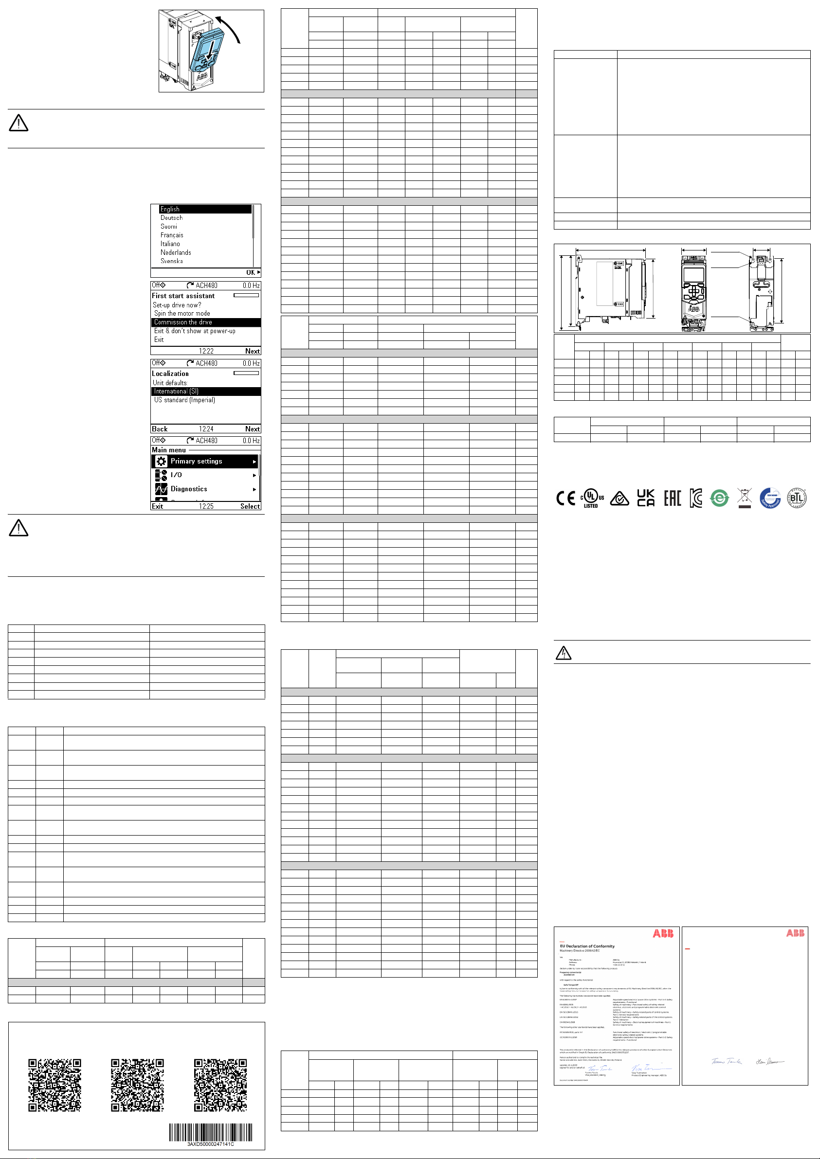
11. Install the control panel
To install the control panel:
1. Close the front cover and tighten the
screw.
2. Put the bottom edge of the control panel
into position.
3. Push the top of the control panel until it
locks into position.
12. Start up the drive
WARNING! Before you start up the drive, make sure that the installation
is completed. Make sure also that it is safe to start the motor.
Disconnect the motor from other machinery, if there is a risk of
damage or injury.
The control panel has softkeys below the display to access the related
commands, and arrow keys to navigate the menu and change parameter values.
Push the “?” button to open the help function.
Make sure that you have the motor nameplate data available.
1. Power up the drive. The first start assistant runs automatically. Wait until the
control panel shows the language selection list.
2. Select the user interface language with
the arrow keys, then push the right
softkey (OK).
3. Select
Commission the drive
and push
the right softkey (Next).
4. Select the localization and push the
right softkey (Next).
5. To complete the first start assistant,
enter the settings and values when you
are prompted.
You can also use Primary settings in the
Main menu to configure the unit.
In Primary settings you can, for example,
set operation limits (speed), and
acceleration and deceleration ramps as
required by the application.
In I/O, you can define external control
signal sources (IO or fieldbus).
WARNING! If you activate the automatic fault reset or automatic
restart functions of the drive control program, make sure that no
dangerous situations can occur. These functions reset the drive
automatically and continue operation after a fault or supply break. If
these functions are activated, the installation must be clearly marked
as defined in IEC/EN 61800-5-1, subclause 6.5.3, for example, “THIS
MACHINE STARTS AUTOMATICALLY”.
Fieldbus settings
If necessary, configure the drive for fieldbus communication. The table below
shows the minimum set of parameters required to configure BACnet MS/TP
communication through the embedded fieldbus interface. If you use a fieldbus
adapter, refer to the applicable fieldbus adapter documentation.
Warnings and faults
Ratings
No. Name Value
20.01 Ext1 commands Embedded fieldbus
22.11 Ext1 speed ref1 (vector) EFB ref1
28.11 Ext1 frequency ref1 (scalar) EFB ref1
31.11 Fault reset selection DI1 1)
1) If you select DI1, you must connect the reset signal to digital input DI1.
58.01 Protocol enable BACnet MSTP
58.03 Node address 1 (default)
58.04 Baud rate Autodetect (default)
58.40 Device object ID User-defined (range 0…4194302)
Warning Fault Description
A2A1 2281 Warning: Current calibration is done at the next start.
Fault: Output phase current measurement fault.
A2B1 2310 Overcurrent. The output current is more than the internal limit. This can
be caused by an earth fault or phase loss.
A2B3 2330 Earth leakage. A load unbalance that is typically caused by an earth fault
in the motor or the motor cable.
A2B4 2340 Short circuit. There is a short circuit in the motor or the motor cable.
- 3130 Input phase loss. The intermediate DC circuit voltage oscillates.
- 3181 Cross connection. The input and motor cable connections are incorrect.
A3A1 3210 DC link overvoltage. There is an overvoltage in the intermediate DC
circuit.
A3A2 3220 DC link undervoltage. There is an undervoltage in the intermediate DC
circuit.
- 3381 Output phase loss. All three phases are not connected to the motor.
A5A0 5091 Safe torque off. The Safe torque off (STO) function is on.
- 6681 EFB communication loss. There is a problem with the embedded
fieldbus connection.
- 7510 FBA A communication. Communication is lost between drive and
fieldbus adapter, or between controller and fieldbus adapter.
A7AB - Extension I/O configuration failure. The installed extension module is
not the same as configured.
AFF6 - Identification run. The motor ID run occurs at the next start.
- FA81 Safe torque off 1. The Safe torque off circuit 1 is broken.
- FA82 Safe torque off 2. The Safe torque off circuit 2 is broken.
IEC type
ACH480
-04-…
Input ratings Output ratings Frame
size
No choke With choke Max.
current
Nominal use Light-duty use
I
1N
I
1N
I
max
I
N
P
N
I
Ld
P
Ld
AAAAkWAkW
1-phase
U
N= 230 V1)
02A4-1 5.0 4.2 3.2 2.4 0.37 2.3 2.4 R0
03A7-1 7.1 6.4 4.3 3.7 0.55 3.5 3.7 R0
Fuses and typical power cable sizes
Terminal data for the power cables
Note:
• The minimum specified wire size does not necessarily have sufficient current carrying
04A8-1 8.8 8.3 6.7 4.8 0.75 4.6 0.75 R1
06A9-1 12.0 11.9 8.6 6.9 1.10 6.6 1.10 R1
07A8-1 14.2 13.5 12.4 7.8 1.5 7.4 1.5 R1
09A8-1 18.7 17.0 14.0 9.8 2.2 9.3 2.2 R2
12A2-1 24.6 21.1 17.6 12.2 3.0 11.6 3.0 R2
3-phase
U
N= 230 V 1)
02A4-2 3.6 2.4 3.2 2.4 0.37 2.4 0.37 R1
03A7-2 5.1 3.7 4.3 3.7 0.55 3.2 0.55 R1
04A8-2 6.3 4.8 6.7 4.8 0.75 4.6 0.75 R1
06A9-2 8.4 6.9 8.6 6.9 1.1 6.6 1.1 R1
07A8-2 10.1 7.8 12.4 7.8 1.5 7.5 1.5 R1
09A8-2 13.8 9.8 14.0 9.8 2.2 9.3 2.2 R1
12A2-2 17.3 12.2 17.6 12.2 3.0 11.6 3.0 R2
17A5-2 22.2 17.5 22.0 17.5 4.0 16.7 4.0 R3
25A0-2 29.1 25.0 31.5 25.0 5.5 24.2 5.5 R3
032A-2 37.0 32.0 45.0 32.0 7.5 30.8 7.5 R4
048A-2 50.0 48.0 57.6 48.0 11.0 46.2 11.0 R4
055A-2 60.0 55.0 86.4 55.0 15.0 52.8 15.0 R4
3-phase
U
N= 400 V
02A7-4 3.8 2.6 3.2 2.6 0.75 2.5 0.75 R1
03A4-4 5.1 3.3 4.7 3.3 1.1 3.1 1.1 R1
04A1-4 6.4 4.0 5.9 4.0 1.5 3.8 1.5 R1
05A7-4 8.9 5.6 7.2 5.6 2.2 5.3 2.2 R1
07A3-4 10.9 7.2 10.1 7.2 3.0 6.8 3.0 R1
09A5-4 13.9 9.4 13.0 9.4 4.0 8.9 4.0 R1
12A7-4 17.6 12.6 16.9 12.6 5.5 12.0 5.5 R2
018A-4 25.2 17.0 22.7 17.0 7.5 16.2 7.5 R3
026A-4 34.1 25.0 30.6 25.0 11.0 23.8 11.0 R3
033A-4 43.4 32.0 45.0 32.0 15.0 30.5 15.0 R4
039A-4 52.3 38.0 57.6 38.0 18.5 36.0 18.5 R4
046A-4 56.0 45.0 68.4 45.0 22.0 42.8 22.0 R4
050A-4 58.9 50.0 81.0 50.0 22.0 48.0 22.0 R4
UL (NEC)
type
ACH480
-04-…
Input ratings Output ratings Frame
size
No choke With choke Max. current Light-duty use
I
1Ld
I
1Ld
I
max
I
Ld
P
Ld
AA A A hp
1-phase
U
N= 230 V1)
02A3-1 4.8 4.0 3.2 2.3 0.5 R0
03A5-1 6.8 6.1 4.3 3.5 0.8 R0
04A6-1 8.2 8.0 6.7 4.6 1.0 R1
06A6-1 12.0 11.4 8.6 6.6 1.5 R1
07A4-1 13.0 12.8 12.4 7.4 2.0 R1
09A3-1 18.0 16.1 14.0 9.3 3.0 R2
11A6-1 20.6 20.1 17.6 11.6 3.0 R2
3-phase
U
N= 230 V 1)
02A3-2 3.5 2.4 3.2 2.4 0.5 R1
03A5-2 4.8 3.2 4.3 3.2 0.75 R1
04A6-2 5.8 4.6 6.7 4.6 1.0 R1
06A6-2 8.3 6.6 8.6 6.6 1.5 R1
07A5-2 9.2 7.5 12.4 7.5 2.0 R1
11A6-2 12.8 11.6 17.6 11.6 3.0 R2
017A-2 20.5 16.7 22.0 16.7 5.0 R3
024A-2 29.7 24.2 31.5 24.2 7.5 R3
031A-2 36.0 30.8 45.0 30.8 10.0 R4
046A-2 50.5 46.2 57.6 46.2 15.0 R4
053A-2 57.6 52.8 86.4 52.8 20.0 R4
3-phase
U
N= 480 V
02A1-4 3.0 2.1 3.2 2.1 1.0 R1
03A0-4 4.3 3.0 4.7 3.0 1.5 R1
03A5-4 4.9 3.5 5.9 3.5 2.0 R1
04A8-4 6.7 4.8 7.2 4.8 3.0 R1
06A0-4 6.7 6.0 10.1 6.0 3.0 R1
07A6-4 10.6 7.6 13.0 7.6 5.0 R1
011A-4 14.9 11.0 16.9 11.0 7.5 R2
014A-4 20.2 14.0 22.7 14.0 10.0 R3
021A-4 28.5 21.0 30.6 21.0 15.0 R3
027A-4 35.8 27.0 45.0 27.0 20.0 R4
034A-4 43.8 34.0 57.6 34.0 25.0 R4
042A-4 49.4 42.0 81.0 42.0 30.0 R4
1) 230 V drives not available at the time of publication. For availability, contact ABB.
IEC type
ACH480
-04-…
UL (NEC)
type
ACH480
-04-…
Fuses Cable conductor
sizes (Cu)
Frame
size
gG gR UL class
T1) 2) 3)
1) The recommended branch protection fuses must be used to maintain the
IEC/EN/UL 61800-5-1 listing.
2) The drive is suitable for use on a circuit capable of delivering not more than
100000 symmetrical amperes (rms) at 480 V (480 V drive types) or 240 V (240 V drive types)
maximum when protected by the fuses given in this table.
3) As an alternative to Class T fuses, you can use Class J or Class CF fuses of the same voltage
and current rating for branch circuit protection of 3-phase drives.
ABB type Bussmann
type
Bussmann/
Edison type
mm2AWG
1-phase
U
N= 230 V
02A4-1 02A3-1 OFAF000H10 170M2695 JJN/TJN10 3×1.5 + 1.5 16 R0
03A7-1 03A5-1 OFAF000H10 170M2695 JJN/TJN10 3×1.5 + 1.5 16 R0
04A8-1 04A6-1 OFAF000H16 170M2696 JJN/TJN20 3×1.5 + 1.5 16 R1
06A9-1 06A6-1 OFAF000H20 170M2697 JJN/TJN20 3×1.5 + 1.5 16 R1
07A8-1 07A4-1 OFAF000H25 170M2698 JJN/TJN25 3×1.5 + 1.5 16 R1
09A8-1 09A3-1 OFAF000H32 170M2698 JJN/TJN25 3×2.5 + 2.5 14 R2
12A2-1 11A6-1 OFAF000H35 170M2698 JJN/TJN35 3×2.5 + 2.5 14 R2
3-phase
U
N= 230 V
02A4-2 02A3-2 OFAF000H6 170M2694 JJS/TJS6 3×1.5 + 1.5 16 R1
03A7-2 03A5-2 OFAF000H10 170M2695 JJS/TJS10 3×1.5 + 1.5 16 R1
04A8-2 04A6-2 OFAF000H10 170M2695 JJS/TJS10 3×1.5 + 1.5 16 R1
06A9-2 06A6-2 OFAF000H16 170M2696 JJS/TJS20 3×1.5 + 1.5 16 R1
07A8-2 07A5-2 OFAF000H16 170M2696 JJS/TJS20 3×1.5 + 1.5 16 R1
09A8-2 - OFAF000H16 170M2696 JJS/TJS20 3×2.5 + 2.5 14 R1
12A2-2 11A6-2 OFAF000H25 170M2697 JJS/TJS25 3×2.5 + 2.5 14 R2
17A5-2 017A-2 OFAF000H32 170M2698 JJS/TJS35 3×6 + 6 10 R3
25A0-2 024A-2 OFAF000H50 170M2699 JJS/TJS50 3×6 + 6 10 R3
032A-2 031A-2 OFAF000H63 170M2700 JJS/TJS60 3×10 + 10 8 R3
048A-2 046A-2 OFAF000H100 170M2702 JJS/TJS100 3×25 + 16 4 R4
055A-2 053A-2 OFAF000H100 170M2702 JJS/TJS100 3×25 + 16 4 R4
3-phase
U
N= 400 V or 480 V
02A7-4 02A1-4 OFAF000H6 170M2694 JJS/TJS6 3×1.5 + 1.5 16 R1
03A4-4 03A0-4 OFAF000H6 170M2694 JJS/TJS6 3×1.5 + 1.5 16 R1
04A1-4 03A5-4 OFAF000H10 170M2695 JJS/TJS10 3×1.5 + 1.5 16 R1
05A7-4 04A8-4 OFAF000H10 170M2695 JJS/TJS10 3×1.5 + 1.5 16 R1
07A3-4 06A0-4 OFAF000H16 170M2696 JJS/TJS20 3×1.5 + 1.5 16 R1
09A5-4 07A6-4 OFAF000H16 170M2696 JJS/TJS20 3×2.5 + 2.5 14 R1
12A7-4 011A-4 OFAF000H25 170M2697 JJS/TJS25 3×2.5 + 2.5 14 R2
018A-4 014A-4 OFAF000H32 170M2698 JJS/TJS35 3×6 + 6 10 R3
026A-4 021A-4 OFAF000H50 170M2699 JJS/TJS40 3×6 + 6 10 R3
033A-4 027A-4 OFAF000H63 170M2700 JJS/TJS60 3×10 + 10 8 R4
039A-4 034A-4 OFAF000H80 170M2701 JJS/TJS80 3×16 + 16 6 R4
046A-4 - OFAF000H100 170M2702 JJS/TJS100 3×25 + 16 4 R4
050A-4 042A-4 OFAF000H100 170M2702 JJS/TJS100 3×25 + 16 4 R4
Frame
size
L1, L2, L3, T1/U, T2/V, T3/W, R-, R+/UDC+, UDC- PE
Min. wire size
(solid/
stranded)
Max. wire size
(solid/
stranded)
Tightening
torque
Max. wire size
(solid/
stranded)
Tightening
torque
mm2AWG mm2AWG N·m lbf·in mm2AWG N·m lbf·in
R0 0.5/0.5 18 4/2.5 10 0.5…0.6 5 6/4 10 1.2 11
R1 0.5/0.5 18 4/2.5 10 0.5…0.6 5 6/4 10 1.2 11
R2 0.5/0.5 18 4/2.5 10 0.5…0.6 5 6/4 10 1.2 11
R3 0.5/0.5 18 10/6 6 1.2…1.5 11…13 6/4 10 1.2 11
R4 0.5/0.5 18 25/16 2 2.5…3.7 22…32 25/16 4 2.9 26
IEC type
ACH480
-04-…
Input ratings Output ratings Frame
size
No choke With choke Max.
current
Nominal use Light-duty use
I
1N
I
1N
I
max
I
N
P
N
I
Ld
P
Ld
AAAAkWAkW
capacity at maximum load.
• The terminals do not accept a conductor that is one size larger than the maximum
specified wire size.
• The maximum number of conductors per terminal is 1.
Ambient conditions
Dimensions and weights
Free space requirements
Markings
The applicable markings are shown on the type designation label of the drive.
Safe torque off (STO)
The drive has a Safe torque off function (STO) in accordance with
IEC/EN 61800-5-2. It can be used, for example, as the final actuator device of
safety circuits that stop the drive in case of danger (such as an emergency stop
circuit).
When activated, the STO function disables the control voltage of the power
semiconductors of the drive output stage, thus preventing the drive from
generating the torque required to rotate the motor. The control program
generates an indication as defined by parameter
31.22
. If the motor is running
when Safe torque off is activated, it coasts to a stop. Closing the activation
switch deactivates the STO. Any faults generated must be reset before
restarting.
The STO function has a redundant architecture, that is, both channels must be
used in the safety function implementation. The safety data given is calculated
for redundant use, and does not apply if both channels are not used.
WARNING! The STO function does not disconnect the voltage from the
main and auxiliary circuits of the drive.
Notes:
• If stopping by coasting is not acceptable, stop the drive and machinery using
the appropriate stop mode before activating the STO.
• The STO function overrides all other functions of the drive.
Wiring
The safety contacts must open/close within 200 ms of each other.
Double-shielded twisted-pair cable is recommended for the connection. The
maximum length of the cabling between the switch and the drive control unit is
300 m (1000 ft). Ground the shield of the cable at the control unit only.
Validation
To ensure the safe operation of a safety function, a validation test is required.
The test must be carried out by a competent person with adequate expertise
and knowledge of the safety function. The test procedures and report must be
documented and signed by this person. Validation instructions of the STO
function can be found in the drive hardware manual.
Technical data
• Minimum voltage at IN1 and IN2 to be interpreted as “1”: 13 V DC
• STO reaction time (shortest detectable break): 1 ms
• STO response time: 2 ms (typical), 5 ms (maximum)
• Fault detection time: Channels in different states for longer than 200 ms
• Fault reaction time: Fault detection time + 10 ms
• STO fault indication (parameter
31.22
) delay: < 500 ms
• STO warning indication (parameter
31.22
) delay: < 1000 ms
• Safety integrity level (EN 62061): SIL 3
• Performance level (EN ISO 13849-1): PL e
The drive STO is a type A safety component as defined in IEC 61508-2.
For the full safety data, exact failure rates and failure modes of the STO
function, refer to the drive hardware manual.
Declarations of conformity
Requirement During operation (installed for stationary use)
Installation altitude 230 V drives:
0 … 2000 m (0 … 6562 ft) above sea level.
400/480 V drives:
0 … 4000 m (0 … 13123 ft) above sea level.
At altitudes above 2000 m (6562 ft):
• only TN-S and TT grounding systems are permitted
• the maximum permitted voltage for the integrated relay outputs
decreases. At 4000 m (13123 ft), it is 30 V.
Derating:
The output current must be derated 1% for each 100 m (328 ft) above
1000 m (3281 ft).
Surrounding air
temperature
Frame R0:
-10 … +50 °C (14 … 122 °F). No frost permitted.
Frames R1…R4:
-10 … +60 °C (14 … 140 °F). No frost permitted.
The output current must be derated at temperatures above +50 °C
(122 °F) as follows:
• IEC types 055A-2, 039A-4, 050A-4 and UL (NEC) types 053A-2,
034A-4 and 042A-4: 2% for each added 1 °C (1.8°F)
• Other types: 1% for each added 1 °C (1.8°F).
Relative humidity 5 … 95%. No condensation permitted. Maximum permitted relative
humidity is 60% in the presence of corrosive gases.
Contamination levels No conductive dust permitted
Shock or free fall Not permitted
Frame
size
Dimensions Weights
H1 H2 H3 W D M1 M2
mm in mm in mm in mm in mm in mm in mm in kg lb
R0 205 8.1 223 8.8 170 6.7 73 2.9 208 8.2 50 2.0 191 7.5 1.70 3.74
R1 205 8.1 223 8.8 170 6.7 73 2.9 208 8.2 50 2.0 191 7.5 1.77 3.90
R2 205 8.1 223 8.8 170 6.7 97 3.8 208 8.2 75 3.0 191 7.5 2.35 5.19
R3 205 8.1 220 8.7 170 6.7 172 6.8 208 8.2 148 5.8 191 7.5 3.52 7.76
R4 205 8.1 240 9.5 170 6.7 262 10.3 213 8.4 234 9.2 191 7.5 6.02 13.3
Frame size Above Below Sides 1)
1) A side-mounted option requires approximately 20 mm (0.8 in) of space on the right side of
the drive.
mm in mm in mm in
R0…R4 75 3 75 3 0 0
CE UL RCM UKCA EAC KC EIP green WEEE TÜV Nord BTL
D
H2
M2
Ø 5 mm (0.2”)
Ø 10 mm (0.4”)
Ø 5 mm (0.2”)
Declaration of Conformity
Supply of Machinery (Safety) Regulations 2008
xxxxxxxxxxxxxxxxxxxxxxxxxxxxxxxxxxxxxxxxx xxxxxxxxxxxxxxxxxxxxxxxxxxx
We
Manufacturer:
Address:
Phone:
Frequency converter
with regard to the safety function
The following harmonized standards have been applied:
EN 61800-5-2:2007
EN 62061:2005
+ AC:2010 + A1:2013 + A2:2015
EN ISO 13849-1:2015
EN ISO 13849-2:2012
EN 60204-1:2018
The following other standards have been applied:
IEC 61508:2010, parts 1-2
IEC 61800-5-2:2016
Helsinki, May 7, 2021
Signed for and on behalf of:
Tuomo Tarula
Local Division Manager, ABB Oy
Document number 3AXD10001329519
ABB Oy
Hiomotie 13, 00380 Helsinki, Finland.
+358 10 22 11
is in conformity with all the relevant safety component requirements of the Supply of Machinery (Safety) Regulations 2008, when the listed safety
function is used for safety component functionality.
Adjustable speed electrical power drive systems – Part 5-2: Safety requirements -
Functional
Safety of machinery – Functional safety of safety-related electrical, electronic and
programmable electronic control systems
declare under our sole responsibility that the following product:
ACH480-04
Safe Torque Of
Functional safety of electrical / electronic / programmable electronic safety-
related systems
Adjustable speed electrical power drive systems – Part 5-2: Safety requirements -
Functional
Safety of machinery – Safety-related parts of control systems. Part 1: General
requirements
Safety of machinery – Safety-related parts of the control systems. Part 2:
Validation
Safety of machinery – Electrical equipment of machines – Part 1: General
requirements
Product Unit Manager, ABB Oy
Harri Mustonen
The product(s) referred in this declaration of conformity fulfil(s) the relevant provisions of other UK statutory requirements, which are notifiedin
a single declaration of conformity 3AXD10001324375.
Authorized to compile the technical file: ABB Limited, Daresbury Park, Cheshire, United Kingdom, WA4 4BT.


