manuals.online logo
Brands
  1. Home
  2. •
  3. Brands
  4. •
  5. ABB
  6. •
  7. DC Drive
  8. •
  9. ABB ACH580-01 Series User manual

ABB ACH580-01 Series User manual

Other manuals for ACH580-01 Series

12

This manual suits for next models

1

Other ABB DC Drive manuals

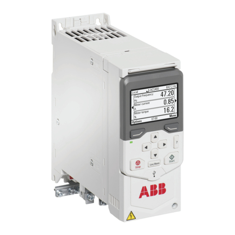
ABB ACS380 Series Installation manual

ABB

ABB ACS380 Series Installation manual

ABB ACH580-01 Series User manual

ABB

ABB ACH580-01 Series User manual

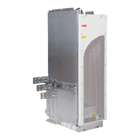
ABB ACS880-01 Series User manual

ABB

ABB ACS880-01 Series User manual

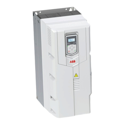
ABB ACH580-31 User manual

ABB

ABB ACH580-31 User manual

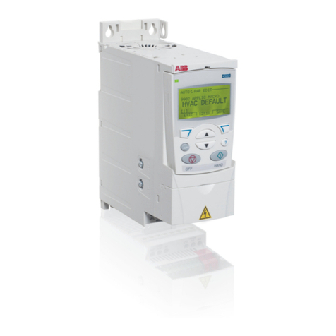
ABB ACS310 User manual

ABB

ABB ACS310 User manual

ABB ACS880 Series Owner's manual

ABB

ABB ACS880 Series Owner's manual

ABB ACS 800 Series User manual

ABB

ABB ACS 800 Series User manual

ABB ACS850 series User manual

ABB

ABB ACS850 series User manual

ABB +Q951 Product information sheet

ABB

ABB +Q951 Product information sheet

ABB ACS880-07XT Series User manual

ABB

ABB ACS880-07XT Series User manual

ABB ACS880 Series User manual

ABB

ABB ACS880 Series User manual

ABB ACS880-01 Series User manual

ABB

ABB ACS880-01 Series User manual

ABB DCS800 User manual

ABB

ABB DCS800 User manual

ABB HD4-HXA Operating and installation instructions

ABB

ABB HD4-HXA Operating and installation instructions

ABB ACS355 series Installation manual

ABB

ABB ACS355 series Installation manual

ABB DCS800 User manual

ABB

ABB DCS800 User manual

ABB ACS380 Series Use and care manual

ABB

ABB ACS380 Series Use and care manual

ABB ACQ80-04 Series Installation manual

ABB

ABB ACQ80-04 Series Installation manual

ABB ACQ80-01 Installation manual

ABB

ABB ACQ80-01 Installation manual

ABB ACS880 Series User manual

ABB

ABB ACS880 Series User manual

ABB ACS860 Use and care manual

ABB

ABB ACS860 Use and care manual

ABB ACS850-04 series User manual

ABB

ABB ACS850-04 series User manual

ABB R6 User manual

ABB

ABB R6 User manual

ABB ACS800-U7 User manual

ABB

ABB ACS800-U7 User manual

Popular DC Drive manuals by other brands

National Instruments NI MID-7604 user guide

National Instruments

National Instruments NI MID-7604 user guide

SOMFY Maestria WT Series instructions

SOMFY

SOMFY Maestria WT Series instructions

Danfoss VLT HVAC Design guide

Danfoss

Danfoss VLT HVAC Design guide

Trane TR150 Service manual

Trane

Trane TR150 Service manual

Chamberlain Garog D Series operating manual

Chamberlain Garog

Chamberlain Garog D Series operating manual

Parker PDS Series user guide

Parker

Parker PDS Series user guide

Binks QS-5012-1-CE Service manual

Binks

Binks QS-5012-1-CE Service manual

Danfoss VLT 2800 Series Quick setup

Danfoss

Danfoss VLT 2800 Series Quick setup

YASKAWA CANopen SI-S3 Technical manual

YASKAWA

YASKAWA CANopen SI-S3 Technical manual

GE D20A6 instructions

GE

GE D20A6 instructions

Danfoss VLT AQUA Drive FC 202 operating manual

Danfoss

Danfoss VLT AQUA Drive FC 202 operating manual

Lenze PositionServo 940 user manual

Lenze

Lenze PositionServo 940 user manual

Unex MC-D-250-1000-050W-TW operating manual

Unex

Unex MC-D-250-1000-050W-TW operating manual

Geckodrive G213V manual

Geckodrive

Geckodrive G213V manual

Rockwell Automation PowerFlex 700S Programming manual

Rockwell Automation

Rockwell Automation PowerFlex 700S Programming manual

WEG DeviceNet CFW500 user manual

WEG

WEG DeviceNet CFW500 user manual

Siemens SINAMICS G List manual

Siemens

Siemens SINAMICS G List manual

Siemens SINAMICS SM150 6SL3815-7NP41-0AA1 Operating instructions & installation instructions

Siemens

Siemens SINAMICS SM150 6SL3815-7NP41-0AA1 Operating instructions & installation instructions

manuals.online logo
manuals.online logoBrands
  • About & Mission
  • Contact us
  • Privacy Policy
  • Terms and Conditions

Copyright 2025 Manuals.Online. All Rights Reserved.

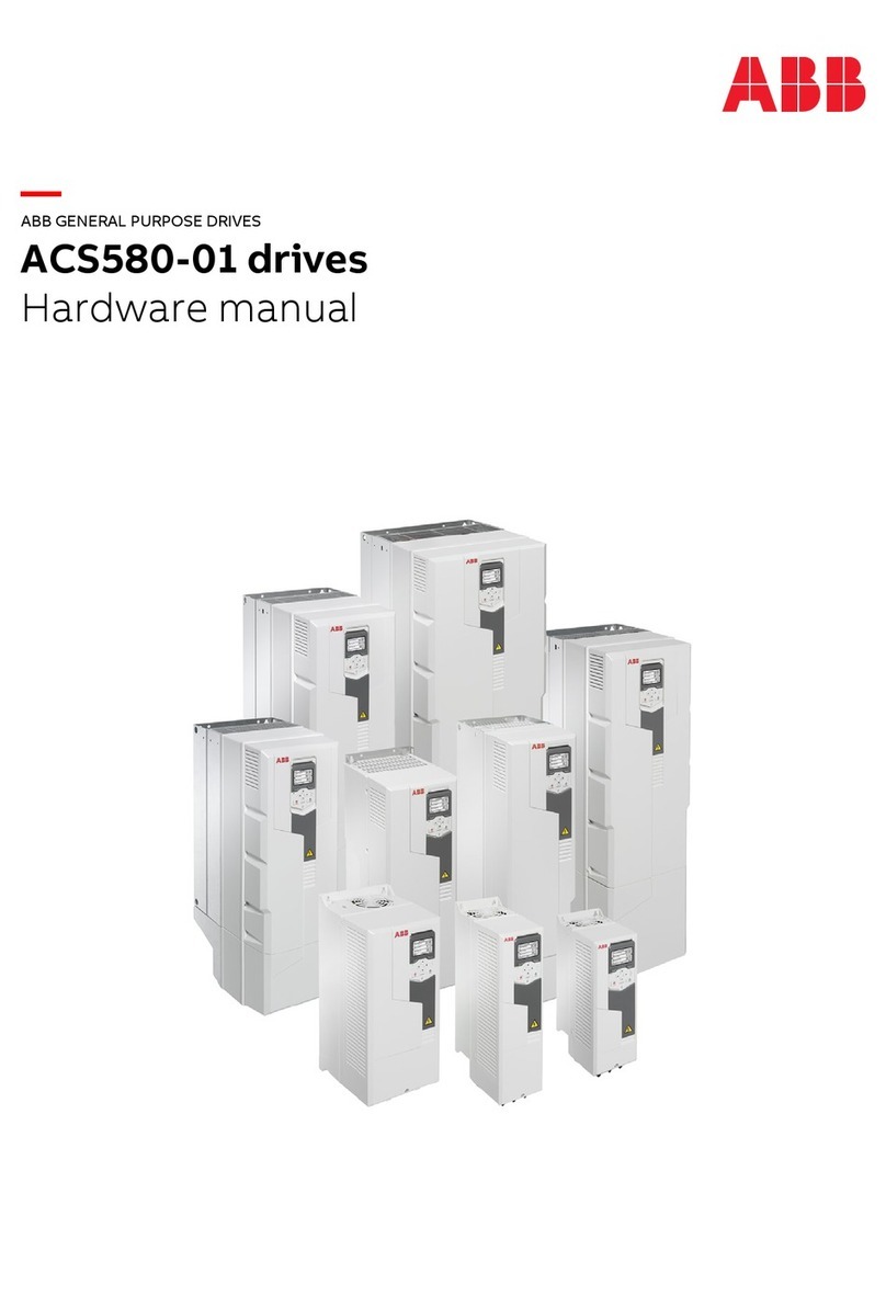
ABB drivesforHVAC
Hardware manual
ACH580-01 drives
(0.75 to250 kW, 1to350 hp)
Listofrelated manuals
Youcan find manualsand otherproduct documentsin PDF format on the Internet. See section Document
libraryonthe Internet on the insideofthe backcover.Formanualsnot availablein the Document library,
contactyourlocal ABBrepresentative.
Drive manualsandguidesCode(English)
ACH580HVACcontrolprogramfirmwaremanual 3AXD50000027537
ACH580-01(0.75 to250 kW,1to350 hp)hardware
manual
3AUA0000076331
ACH580-01quick installationandstart-up guidefor
framesR0toR5
3AUA0000076330
ACH580-01quick installationandstart-up guidefor
framesR6toR9
3AXD50000036602
ACS-AP-xassistant controlpanelsuser smanual 3AUA0000085685
Optionmanualsand guides
CPTC-02ATEX-certifiedthermistorprotection module,
ExII(2)GD(+L537+Q971)user'smanual
3AXD50000032016
CDPI-01 communication adaptermoduleuser'smanual 3AXD50000009929
DPMP-01mounting platformforACS-AP controlpanel 3AUA0000100140
DPMP-02/03 mountingplatformforACS-AP controlpanel 3AUA0000136205
FBIP-21BACnet/IPadaptermodule 3AXD50000028468
FCAN-01CANopenadaptermoduleuser'smanual 3AFE68615500
FCNA-01ControlNetadaptermoduleuser'smanual 3AUA0000141650
FDNA-01DeviceNet!adaptermoduleuser'smanual 3AFE68573360
FECA-01 EtherCATadaptermoduleuser'smanual 3AUA0000068940
FENA-01/-11/-21 Ethernetadaptermoduleuser's
manual
3AUA0000093568
FEPL-02 Ethernet POWERLINKadaptermoduleuser's
manual
3AUA0000123527
FLON-01 LONWORKS®adaptermoduleuser smanual 3AUA0000041017
FPBA-01 PROFIBUSDPadaptermoduleuser'smanual 3AFE68573271
FSCA-01 RS-485 adaptermoduleuser'smanual 3AUA0000109533
Flangemountingkit installation supplement 3AXD50000019100
Flangemountingkit quickinstallationguidefor
ACX580-01framesR0toR5
3AXD50000036610
Flangemountingkit quickinstallationguidefor
ACS880-01and ACX580-01framesR6toR9
3AXD50000019099
Tool and maintenancemanualsand guides
DrivecomposerPCtooluser'smanual 3AUA0000094606
Convertermodulecapacitorreforminginstructions 3BFE64059629
NETA-21 remotemonitoringtooluser'smanual 3AUA00000969391
NETA-21 remotemonitoringtoolinstallation and start-up
guide
3AUA0000096881
ACH580-01manuals
Hardwaremanual
ACH580-01drives
(0.75 to250kW, 1to350 hp)
3AUA0000076331RevB
EN
EFFECTIVE:2016-04-14
2016 ABB Oy.AllRightsReserved.
1.Safetyinstructions
Tableof contents
4.Mechanicalinstallation
6.Electricalinstallation
Tableofcontents5
Tableofcontents
List of relatedmanuals. .. ... . ... . .. .. .. .. .. . ... . ... . ... . .. .. .. .. .. . ... . ... . ..2
1.Safetyinstructions
Contentsof thischapter.. . ... . ... . .. .. .. .. .. . ... . ... . ... . .. .. .. .. .. . ... . ... . .13
Useof warningsand notesinthismanual... .. .. .. . ... . ... . .. .. .. .. .. . ... . ... . ...13
Generalsafetyininstallation,start-upand maintenance. ... . ... . .. .. .. .. .. . ... . ... . .14
Electricalsafetyininstallation,start-upand maintenance... . ... . .. .. .. .. .. . ... . ... . .16
Precautionsbeforeelectricalwork. .. .. .. .. .. . ... . ... . .. .. .. .. .. . ... . ... . ...16
Additionalinstructionsandnotes.. .. .. .. .. . ... . ... . ... . .. .. .. .. .. . ... . ... . .17
Grounding. .. .. .. . ... . .. ... . .. .. .. .. .. . ... . ... . ... . .. .. .. .. .. . ... . .....18
Additionalinstructionsforpermanentmagnet motordrives... . .. .. .. .. .. . ... . ... . ...19
Safetyininstallation,start-up andmaintenance.. ... . ... . .. .. .. .. .. . ... . ... . ...19
Generalsafetyinoperation ... . ... . .. .. .. .. .. . ... . ... . ... . .. .. .. .. .. . ... . ... . .20
2.Introduction to themanual
Contentsof thischapter.. . ... . ... . .. .. .. .. .. . ... . ... . ... . .. .. .. .. .. . ... . ... . .21
Applicability. .. .. .. .. .. . ... . ... . .. .. .. .. .. . ... . ... . ... . .. .. .. .. .. . ... . ... . .21
Target audience.. . . .. .. . ... . ... . .. .. .. .. .. . ... . ... . ... . .. .. .. .. .. . ... . ... . .21
Purposeofthe manual. .. ... . ... . .. .. .. .. .. . ... . ... . ... . .. .. .. .. .. . ... . ... . .21
Contentsofthismanual.. . ... . ... . .. .. .. .. .. . ... . ... . ... . .. .. .. .. .. . ... . ... ..22
Relateddocuments. .. .. . ... . ... . .. .. .. .. .. . ... . ... . ... . .. .. .. .. .. . ... . .. .. .22
Categorizationbyframe(size).. ... . .. .. .. .. .. . ... . ... . ... . .. .. .. .. .. . ... . ... . .23
Quickinstallation andcommissioningflowchart.. . ... . ... . ... . .. .. .. .. .. . ... . ... . .24
3.Operation principleandhardwaredescription
Contentsof thischapter.. . ... . ... . .. .. .. .. .. . ... . ... . ... . .. .. .. .. .. . ... . ... . .27
Operation principle. .. .. . ... . ... . .. .. .. .. .. . ... . ... . ... . .. .. .. .. .. . ... . . . ...28
Layout .. . .. .... .. .. .. . ... . ... . .. .. .. .. .. . ... . ... . ... . .. .. .. .. .. . ... . .. ...29
Overviewofpowerand controlconnections. .. .. . ... . ... . ... . .. .. .. .. .. . ... . ... . .31
Externalcontrolconnection terminals,framesR0 R5... .. . .. .. .. .. .. . ... . ... . .32
Externalcontrolconnection terminals,framesR6 R9. . ... . .. .. .. .. .. . ... . ... . .33
Controlpanel.. .. .. .. .. . ... . ... . .. .. .. .. .. . ... . ... . ... . .. .. .. .. .. . ... . . . ...34
Type designation label. . ... . ... . ... . .. .. .. .. .. . ... . ... . .. .. .. .. .. . ... . ... . . . .35
Locationsofthe labelson the drive. .. .. .. .. .. . ... . ... . .. .. .. .. .. . ... . ... . ...36
Type designationkey. . .. . ... . ... . .. .. .. .. .. . ... . ... . ... . .. .. .. .. .. . ... . ... . .37
4.Mechanicalinstallation
Contentsof thischapter.. . ... . ... . .. .. .. .. .. . ... . ... . ... . .. .. .. .. .. . ... . ... . .39
Safety.. . . . .. .. .. .. .. . ... . ... . .. .. .. .. .. . ... . ... . ... . .. .. .. .. .. . ... . .. ...39
Checking the installationsite.. . ... . .. .. .. .. .. . ... . ... . ... . .. .. .. .. .. . ... . ... . .40
Requiredtools. .. .. .. . ... . ... . ... . .. .. .. .. .. . ... . ... . .. .. .. .. .. . ... . . ... ...42
Movingthe drive. . . .. .. . ... . ... . .. .. .. .. .. . ... . ... . ... . .. .. .. .. .. . ... . ... . .42
Unpackingand examiningdelivery,framesR0 R4... . ... . ... . .. .. .. .. .. . ... . ... . .43
Safety
6Tableof contents
Unpacking andexaminingdelivery,frameR5.. .. .. .. .. . ... . ... . .. .. .. .. .. . ... . ..44
FrameR5cablebox(IP21,ULType 1).. .. .. .. .. . ... . ... . ... . .. .. .. .. .. . ... .45
Unpacking andexaminingdelivery,framesR6 R9. .. .. . ... . ... . .. .. .. .. .. . ... . ..46
FrameR6cablebox(IP21,ULType 1).. .. .. .. .. . ... . ... . ... . .. .. .. .. .. . ... .47
FrameR7cablebox(IP21,ULType 1).. .. .. .. .. . ... . ... . ... . .. .. .. .. .. . ... .48
FrameR8cablebox(IP21,ULType 1).. .. .. .. .. . ... . ... . ... . .. .. .. .. .. . ... .49
FrameR9cablebox(IP21,ULType 1).. .. .. .. .. . ... . ... . ... . .. .. .. .. .. . ... .50
Installingthedrive.. .. .. .. . ... . ... . ... . .. .. .. .. .. . ... . ... . .. .. .. .. .. . . . . . ..51
Installing the drivevertically,framesR0 R4. .. .. . ... . ... . ... . .. .. .. .. .. . ... .51
Installing the drivevertically,frameR5. . .. .. .. .. .. . ... . ... . .. .. .. .. .. . ... . ..53
Installing the drivevertically,framesR6 R9. .. .. . ... . ... . ... . .. .. .. .. .. . ... .56
Installing the driveverticallysidebyside ... .. .. .. . ... . ... . ... . .. .. .. .. .. . ... .57
Installing the drivehorizontally,framesR0 R3. .. . ... . ... . ... . .. .. .. .. .. . ... .57
Flangemounting .. .. .. .. .. . ... . ... . ... . .. .. .. .. .. . ... . ... . .. .. .. .. .. . ... .. .58
5.Planning theelectrical installation
Contentsofthischapter.. .. . ... . ... . ... . .. .. .. .. .. . ... . ... . .. .. .. .. .. . ... . . .59
Selecting thesupplydisconnecting device. .. .. .. .. .. .. . ... . ... . .. .. .. .. .. . ... . ..59
EuropeanUnion... .. .. . ... . ... . ... . .. .. .. .. .. . ... . ... . .. .. .. .. .. . ... . ..59
Otherregions.. . .. .. .. .. . ... . ... . .. .. .. .. .. . ... . ... . ... . .. .. .. .. .. . ....60
Checkingthecompatibilityof themotoranddrive. .. .. .. . ... . ... . .. .. .. .. .. . ... . ..60
Selecting thepowercables. .. . ... . ... . .. .. .. .. .. .. . ... . ... . .. .. .. .. .. . ... . .. 60
Generalrules. .. .. .. .. .. . ... . ... . .. .. .. .. .. . ... . ... . ... . .. .. .. .. .. . ... .60
Typicalpowercablesizes. . ... . ... . .. .. .. .. .. . ... . ... . ... . .. .. .. .. .. . ... .61
Alternativepowercabletypes.. . ... . .. .. .. .. .. . ... . ... . ... . .. .. .. .. .. . ... .62
Motorcableshield. .. .. . ... . ... . ... . .. .. .. .. . ... . ... . ... . .. .. .. .. .. . ... .63
AdditionalUSrequirements.. . ... . ... . .. .. . . .. . ... . ... . ... . .. .. .. .. .. . ... .63
Selecting thecontrolcables.. ... . ... . ... ... .. .. .. . ... . ... . ... . .. .. .. .. .. . ... .64
Shielding ... . .. .. .. .. .. .. . ... . ... . .. .. .. .. .. . ... . ... . .. .. .. .. .. . ... . ..64
Signalsinseparatecables... . . . ... . .. .. .. .. .. . ... . ... . ... . .. .. .. .. .. . ... .64
Signalsallowed toberuninthe samecable.. .. ... ... . ... . ... . .. .. .. .. .. . ... .64
Relaycable. . . . .. .. .. . ... . ... . ... . .. .. .. .. .. . ... . ... . .. .. .. .. .. . ... ...65
Controlpanelcable.. .. .. . ... . ... . .. .. .. .. .. . ... . ... . ... . .. .. .. .. .. . ... .65
DrivecomposerPCtoolcable. ... .. . .. .. .. .. .. . ... . ... . ... . .. .. .. .. .. . ... .65
FPBA-01 PROFIBUSDPadaptermoduleconnectors. . ... . ... . .. .. .. .. .. .. . ... .65
Routing the cables.. .. .. .. . ... . ... . ... . .. .. .. .. .. . ... . ... . .. .. .. .. .. . ... .. .66
Generalrules. .. .. .. .. .. . ... . ... . .. .. .. .. .. . ... . ... . ... . .. .. .. .. .. . ... .66
Separatecontrolcableducts. . ... . ... . .. .. .. .. .. . ... . . . ... . .. .. .. .. .. . ... .67
Continuousmotorcableshieldorenclosureforequipment on themotorcable.. . ... .67
Implementingthermaloverloadand short-circuit protection. ... . ... . .. .. .. .. .. . ... . ..68
Protectingthe driveandinputpowercableinshort-circuits.. ... . .. .. .. .. .. .. . ... .68
Protectingthe motorand motorcableinshort-circuits.. ... . ... .. . .. .. .. .. .. . ... .68
Protectingthe driveandthe input powerand motorcablesagainstthermaloverload . ..68
Protectingthe motoragainst thermaloverload.. .. . ... . ... . ... . .. .. .. .. .. . ... .68
Protectingthe driveagainstgroundfaults. .. .. .. .. .. . ..... . ... . .. .. .. .. .. . ... . ..69
Residualcurrent devicecompatibility.. .. .. .. .. .. . ... . ... . ... . .. .. .. .. .. . ... .69
Implementingthe Emergency stop function .. .. . . .. .. .. . ... . ... . .. .. .. .. .. . ... . ..69
Implementingthe Safetorque offfunction . .. .. .. .. .. .. . ... . ... . .. .. .. .. .. . ... . ..69
Implementingthe undervoltagecontrol(power-lossride-through)... . .. .. .. .. .. . ... . ..69
Using asafetyswitchbetween thedriveand themotor.. ... . ... . ... . .. .. .. .. .. . ... .70
Tableofcontents7
Usingacontactorbetweenthe driveandthe motor... . ... . ... . .. .. .. .. .. . ... . ... . .70
Protecting the contactsofrelayoutputs.. .. .. .. . ... . ... . ... . .. .. .. .. .. . ... . ... . .70
Limiting relayoutputmaximumvoltagesathighinstallationaltitudes. .. .. .. . ... . ... . ...71
6.Electricalinstallation
Contentsof thischapter.. . ... . ... . .. .. .. .. .. . ... . ... . ... . .. .. .. .. .. . ... . ... . .73
Warnings.. . .. .. .. .. .. . ... . ... . .. .. .. .. .. . ... . ... . ... . .. .. .. .. .. . ... . ... . .73
Requiredtools. .. .. .. . ... . ... . ... . .. .. .. .. .. . ... . ... . .. .. .. .. .. . ... . ... . ...73
Checking the insulationoftheassembly.. .. .. .. . ... . ... . ... . .. .. .. .. .. . ... . ... . .74
Drive. .. .. .. .. .. . ... . ... . ... . .. .. .. .. .. . ... . ... . .. .. .. .. .. . ... . ... . .. .74
Input powercable. .. . ... . ... . .. .. .. . . .. .. . ... . ... . .. .. .. .. .. . ... . ... . ...74
Motorandmotorcable..... . ... . .. .. .. .. .. . ... . ... . .. .. .. .. .. . ... . ... . ...74
BrakeresistorassemblyforR0 R3.. .. .. .. .. . ... . ... . .. .. .. .. .. . ... . ... . ...75
Checking the compatibilitywithIT(ungrounded)andcorner-grounded TNsystems... . ...75
EMCfilter. .. .. .. . ... . ... . ... . .. .. .. .. .. . ... . ... . .. .. .. .. .. . ... . ... . . . .75
Ground-to-phasevaristor... . ... . .. .. .. .. .. . ... . ... .. . .. .. .. .. .. . ... . ... . .76
FramesR0 R3.. .. . ... . ... . . . .. .. .. .. .. . ... . ... . .. .. .. .. .. . ... . ... . ...77
FramesR4 R9... ... . ... . ... . .. .. .. .. .. . ... . ... . .. .. .. .. .. . ... . ... . ...78
Connecting thepowercables. . ... .. . .. .. .. .. .. . ... . ... . .. .. .. .. .. . ... . ... . ...80
Connection diagram. . ... .. . ... . .. .. .. .. .. . ... . ... . .. .. .. .. .. . ... . ... . ...80
Connection procedure,framesR0 R4. .. .. . . . ... . ... . .. .. .. .. .. . ... . ... . ...81
Connection procedure,frameR5. . .. . . .. .. . ... . ... . ... . .. .. .. .. .. . ... . ... . .90
Connection procedure,framesR6 R9. .. .. . . . ... . ... . .. .. .. .. .. . ... . ... . ...96
DCconnection ... . . .. . ... . ... . ... . .. .. .. .. .. . ... . ... . .. .. .. .. .. . ... . ... . ..100
Connecting thecontrolcables... . .. .. .. .. .. .. . ... . ... . ... . .. .. .. .. .. . ... . ... .101
DefaultI/Oconnection diagram(HVACdefaultconfiguration). .. . . .. .. . ... . ... . ..102
Controlcableconnection procedureR0 R9. . ... . ..... . .. .. .. .. .. . ... . ... . ..111
Installing option modules.. ... . ... . .. .. .. .. .. . ... . ... . ... . .. .. .. .. .. . ... . ....117
Mechanicalinstallationofoptionmodules.. .. .. . ... . ... . .. .. .. .. .. . ... . ... . ..117
Wiring themodules. ... . ... . ... . .. .. .. .. .. . ... . ... . .. .. .. .. .. . ... . ... . ..119
Reinstallingcovers. .. .. . ... . ... . .. .. .. .. .. . ... . ... . ... . .. .. .. .. .. . ... . . . ..120
Reinstallingcover,framesR0 R4. .. .. .. .. .. . ... . ... . .. .. .. .. .. . ... . ... . ..120
Reinstallingcovers,frameR5. ... . .. .. .. .. .. . ... . ... . .. .. .. .. .. . ... . ... . ..121
Reinstallingsideplatesand covers,framesR6 R9... . ... . .. .. .. .. .. . ... . ... .122
Connecting aPC. .. .. .. . ... . .. ... . .. .. .. .. .. . ... . ... . .. .. .. .. .. . ... . ... . . .123
7.Installation checklist
Contentsof thischapter.. . ... . ... . .. .. .. .. .. . ... . ... . ... . .. .. .. .. .. . ... . ... .125
Warnings.. . .. .. .. .. .. . ... . ... . .. .. .. .. .. . ... . ... . ... . .. .. .. .. .. . ... . ... .125
Checklist. .. .. .. .. . . .. . ... . ... . .. .. .. .. .. . ... . ... . ... . .. .. .. .. .. . ... . ... .125
8.Maintenanceand hardwarediagnostics
Contentsof thischapter.. . ... . ... . .. .. .. .. .. . ... . ... . ... . .. .. .. .. .. . ... . ... .127
Maintenanceintervals. .. . ... . ... . .. .. .. .. .. . ... . ... . ... . .. .. .. .. .. . ... . ... .127
Descriptionofsymbols. . ... . ... . .. .. .. .. .. . ... . ... . .. .. .. .. .. . ... . ... . ..128
Recommendedannualmaintenanceactionsbytheuser. ... . .. .. .. .. .. . ... . ... .128
Recommendedmaintenanceactionsbytheuser. ... . ... . .. .. .. .. .. . ... . ... . ..128
Heatsink.. . . .. .. .. .. .. . ... . ... . .. .. .. .. .. . ... . ... . ... . .. .. .. .. .. . ... . ... .129
8Tableof contents
Fans.... . ... . .. .. .. .. .. . ... . ... . ... . .. .. .. .. .. . ... . ... . .. .. .. .. .. . ... . .130
Replacingthe maincooling fan,framesR0 R4... .. . ... . ... . .. .. .. .. .. . ... . .130
Replacingthe maincooling fan,framesR5 R8... .. . ... . ... . .. .. .. .. .. . ... . .132
Replacingthe maincooling fans,frameR9... .. .. .. . ... . ... . .. .. .. .. .. . ... . .133
Replacingthe auxiliarycooling fan,framesR5 R9. ... . ... . ... . .. .. .. .. .. . ... 134
Replacingthe auxiliarycooling fan,IP55(ULType 12)framesR0 R2.. .. .. . ... . .135
Replacingthe auxiliarycoolingfan, IP55(ULType 12)framesR3. . .. .. .. .. .. . ... 136
Replacingthe auxiliarycoolingfan, IP55(ULType 12)framesR4. . .. .. .. .. .. . ... 137
Replacingthe auxiliarycooling fan,IP55(ULType 12)framesR8 R9.. .. .. . ... . .138
Capacitors.. . . .. .. .. .. .. . ... . ... . ... . .. .. .. .. .. . ... . ... . .. .. .. .. .. . . .. . .139
Reformingthecapacitors.. . ... . ... . .. .. .. .. .. . ... . ... . ... . .. .. .. .. .. . ... 139
Controlpanel... . .. .. .. .. .. . ... . ... . .. .. .. .. .. . ... . ... . ... . .. .. .. . . . . . ... 140
Cleaning thecontrolpanel.. ... . ... . .. .. .. .. .. . ... . ... . ... . .. .. .. .. .. . ... 140
Replacingthe batteryinthecontrolpanel.. .. .. .. . ... . ... . ... . .. .. .. .. .. . ... 140
LEDs. ... . ... . .. .. .. .. .. . ... . ... . ... . .. .. .. .. .. . ... . ... . .. .. .. .. .. . ... . .141
DriveLEDs.. . .. .. .. .. .. . ... . ... . .. .. .. .. .. . ... . ... . ... . .. .. .. .. . ... ..141
ControlpanelLEDs.. .. .. . ... . ... . .. .. .. .. .. . ... . ... . ... . .. .. .. .. .. . ... 142
9.Technicaldata
Contentsofthischapter.. .. . ... . ... . ... . .. .. .. .. .. . ... . ... . .. .. .. .. .. . ... . . 143
Ratings. . . ... . .. .. .. .. .. . ... . ... . ... . .. .. .. .. .. . ... . ... . .. .. .. .. .. . . . ... 144
IECratings. .. .. .. .. .. . . . ... . ... . .. .. .. .. .. . ... . ... . ... . .. .. .. .. .. . ... 144
NEMAratings. .. .. .. .. .. . ... . ... . .. .. .. .. .. . ... . ... . ... . .. .. .. .. .. . ... 145
Definitions. .. .. .. .. .. .. . ... . ... . .. .. .. .. .. . ... . ... . ... . .. .. .. .. .. . . . .145
Sizing. . . ... . .. .. .. .. .. . ... . ... . .. .. .. .. .. . ... . ... . ... . .. .. .. .. .. . . . .146
Derating. . . . ... . .. .. .. .. .. . ... . ... . .. .. .. .. .. . ... . ... . ... . .. .. .. .. .. . ...146
Ambienttemperaturederating,IP21(ULType 1).. .. . ... . . . ... . .. .. .. .. .. . ... 147
Ambienttemperaturederating,IP55(ULType 12). .. . ... . .. ... . .. .. .. .. .. . ... 148
Switching frequency derating... . ... . .. .. .. .. .. . ... . ... . ... . .. .. .. .. .. . ... 150
Altitude derating . .. .. .. . ... . ... . ... . .. .. .. .. .. . ... . ... . .. .. .. .. .. . ... . .150
Fuses(IEC). ... . .. .. .. . . . ... . ... . ... . .. .. .. .. .. . ... . ... . .. .. .. .. .. . . . ... 151
gGfuses. ... . .. .. .. .. .. . ... . ... . .. .. .. .. .. . ... . ... . ... . .. .. .. .. .. . . . .152
uRand aRfuses.. .. .. .. . ... . ... . .. .. .. .. .. . ... . ... . ... . .. .. .. .. .. . ... 153
Fuses(UL).. ... . .. .. .. .. .. . ... . ... . .. .. .. .. .. . ... . ... . ... . .. .. .. .. .... . .154
Circuitbreakers.. .. .. .. .. .. . ... . ... . .. .. .. .. .. . ... . ... . ... . .. .. .. .. .. . . . .155
Dimensions,weightsand freespacerequirements.. .. .. . ... . ... . .. .. .. .. .. . ... . .156
Losses, cooling dataandnoise.. . ... . ... . .. .. .. .. .. . ... . ... . .. .. .. .. .. . ... . .159
Cooling airflowandheat dissipationforflangemounting (option +C135). .. .. .. . ... 160
Terminalandlead-throughdataforthepowercables.. . ... . .. ... . .. .. .. .. .. . ... . .161
IEC.. . ... . .. .... .. .. .. . ... . ... . .. .. .. .. .. . ... . ... . ... . .. .. .. .. .. . . . .161
US. ... . ... . .. .. .. .. .. . ... . ... . .. .. .. .. .. . ... . ... . ... . .. .. .. .. .. . . . . 163
Terminalandlead-throughdataforthecontrolcables.. .. . ... . ... . .. .. .. .. .. . ... . .165
IEC.. . ... . .. .... .. .. .. . ... . ... . .. .. .. .. .. . ... . ... . ... . .. .. .. .. .. . . . .165
US. ... . ... . .. .. .. .. .. . ... . ... . .. .. .. .. .. . ... . ... . ... . .. .. .. .. .. . . . . 165
Electricalpowernetworkspecification... . .. .. .. .. .. . ... . ... . ... . .. .. .. .. .. . ... 166
Voltage (U1). ... . .. .. .. .. . ... . ... . ... . .. .. .. .. .. . ... . ... . .. .. .. .. .. . . . ... 166
Motorconnectiondata. .. .. . ... . ... . ... . .. .. .. .. .. . ... . ... . .. .. .. .. .. . ... ..166
BrakeresistorconnectiondataforframesR0 R3.. .. . ... . .. ... . .. .. .. .. .. . ... . .169
Controlconnectiondata.. .. . ... . ... . ... . .. .. .. .. .. . ... . ... . .. .. .. .. .. . ... . .169
Efficiency.. . ... . .. .. . . .. . ... . ... . ... . .. .. .. .. .. . ... . ... . .. .. .. .. .. . . . ... 175
Tableofcontents9
Degreeof protection.. . . . ... . ... . .. .. .. .. .. . ... . ... . ... . .. .. .. .. .. . ... . ... .175
Ambient conditions. .. .. . ... . ... . .. .. .. .. .. . ... . ... . ... . .. .. .. .. .. . ... . ... .175
Materials. . . .. .. .. .. .. . ... . ... . .. .. .. .. .. . ... . ... . ... . .. .. .. .. .. . ... . ... .177
Applicablestandards.. .. . ... . ... . .. .. .. .. .. . ... . ... . ... . .. .. .. .. .. . ... . ... .177
CEmarking . .. .. .. .. .. . ... . ... . .. .. .. .. .. . ... . ... . ... . .. .. .. .. .... . ... . ..179
CompliancewiththeEuropeanLowVoltage Directive.. . ... . .. .. .. . . . ... . ... . ..179
CompliancewiththeEuropeanEMCDirective. ... . .. ... . .. .. .. .. .. . ... . ... . ..179
CompliancewiththeEuropeanROHSIIDirective2011/65/EU.. .. .. .. .. . ... . . . ..179
Compliancewiththe EuropeanMachineryDirective2006/42/EC2ndEdition !
June 2010. .. .. .. .. . ... . ... . .. .. .. .. .. . ... . ... . ... . .. .. .. .. .. . ... . ....179
CompliancewiththeEN61800-3:2004 +A1:2012 .. . ... . ... . .. .. . . .. .. .. . ... . ... .180
Definitions... .. .. .. . ... . ... . .. .. .. .. .. . ... . ... . ... . .. .. .. .. .. . ... . ... .180
CategoryC1. .. .. .. . ... . . . ... . .. .. .. .. .. . ... . ... . .. .. .. .. .. . ... . ... . . .180
CategoryC2. . . .. . ... . ... . ... . .. .. .. .. .. . ... . ... . .. .. .. .. .. . ... . ... . . .181
CategoryC3. . . .. . ... . ... . ... . .. .. .. .. .. . ... . ... . .. .. .. .. .. . ... . ... . . .181
CategoryC4. . . .. . ... . ... . ... . .. .. .. .. .. . ... . ... . .. .. .. .. .. . ... . ... . . .182
RCMmarking .. .. .. .. .. . ... . ... . .. .. .. .. .. . ... . ... . ... . .. .. .. .. .. . ... . ... .183
EACmarking .. .. .. .. . ..... . ... . .. .. .. .. .. . ... . ... . ... . .. .. .. .. .. . ... . ... .183
Disclaimer.. .. .. .. .. . ... . ... . ... . .. .. .. .. .. . ... . ... . .. .. .. .. .. . ... . ... . ..183
Cybersecuritydisclaimer.. . ... . ... . .. .. .. .. .. . ... . . . ... . .. .. .. .. .. . ... . ... .183
10. Dimension drawings
Contentsof thischapter.. . ... . ... . .. .. .. .. .. . ... . ... . ... . .. .. .. .. .. . ... . ... .185
FrameR0,IP21 (ULType 1). ... . ... . .. . . .. .. . ... . ... . ... . .. .. .. .. .. . ... . ... .186
FrameR0,IP55 (ULType 12)... . ... . .. .. . . .. . ... . ... . ... . .. .. .. .. .. . ... . ... .187
FrameR1, IP21(ULType 1). ... . ... . .. .... .. . ... . ... . ... . .. .. .. .. .. . ... . ... .188
FrameR1,IP55 (ULType 12)... . ... . .. .. . . .. . ... . ... . ... . .. .. .. .. .. . ... . ... .189
FrameR2,IP21 (ULType 1). ... . ... . .. . . .. .. . ... . ... . ... . .. .. .. .. .. . ... . ... .190
FrameR2,IP55 (ULType 12)... . ... . .. .. . . .. . ... . ... . ... . .. .. .. .. .. . ... . ... .191
FrameR3,IP21 (ULType 1). ... . ... . .. . . .. .. . ... . ... . ... . .. .. .. .. .. . ... . ... .192
FrameR3,IP55 (ULType 12)... . ... . .. .. . . .. . ... . ... . ... . .. .. .. .. .. . ... . ... .193
FrameR4,IP21 (ULType 1). ... . ... . .. . . .. .. . ... . ... . ... . .. .. .. .. .. . ... . ... .194
FrameR4,IP55 (ULType 12)... . ... . .. .. . . .. . ... . ... . ... . .. .. .. .. .. . ... . ... .195
FrameR5,IP21 (ULType 1). ... . ... . .. . . .. .. . ... . ... . ... . .. .. .. .. .. . ... . ... .196
FrameR5,IP55 (ULType 12)... . ... . .. .. . . .. . ... . ... . ... . .. .. .. .. .. . ... . ... .197
FrameR6,IP21 (ULType 1). ... . ... . .. . . .. .. . ... . ... . ... . .. .. .. .. .. . ... . ... .198
FrameR6,IP55 (ULType 12)... . ... . .. .. . . .. . ... . ... . ... . .. .. .. .. .. . ... . ... .199
FrameR7,IP21 (ULType 1). ... . ... . .. . . .. .. . ... . ... . ... . .. .. .. .. .. . ... . ... .200
FrameR7,IP55 (ULType 12)... . ... . .. .. . . .. . ... . ... . ... . .. .. .. .. .. . ... . ... .201
FrameR8,IP21 (ULType 1). ... . ... . .. . . .. .. . ... . ... . ... . .. .. .. .. .. . ... . ... .202
FrameR8,IP55 (ULType 12)... . ... . .. .. . . .. . ... . ... . ... . .. .. .. .. .. . ... . ... .203
FrameR9,IP21 (ULType 1). ... . ... . .. . . .. .. . ... . ... . ... . .. .. .. .. .. . ... . ... .204
FrameR9,IP55 (ULType 12)... . ... . .. .. . . .. . ... . ... . ... . .. .. .. .. .. . ... . ... .205
11. Resistorbraking
Contentsof thischapter.. . ... . ... . .. .. .. .. .. . ... . ... . ... . .. .. .. .. .. . ... . ... .207
Operation principleandhardwaredescription.. .. . ... . ... . ... . .. .. .. .. .. . ... . ... .207
Resistorbraking,framesR0 R3.. . .. .. .. .. .. . ... . ... . ... . .. .. .. .. .. . ... . ... .208
Planningthebraking system.. ... . .. .. .. .. .. . ... . ... . .. .. .. .. .. . ... . ... . ..208
10Tableof contents
Mechanicalinstallation .. . ..... . ... . .. .. .. .. .. . ... . ... . ... . .. .. .. .. .. . ... 212
Electricalinstallation.. .. .. . ... . ... . .. .. .. .. .. . ... . ... . ... . .. .. .. .. .. . ...212
Start-up.. . .. .. .. .. . . .. . ... . ... . .. .. .. .. .. . ... . ... . ... . .. .. .. .. .. . ... 213
Resistorbraking, framesR4 R9.. ... . ... . .. .. .. .. .. . ... . ... . .. .. .. .. .. . ... . .214
Planning thebrakingsystem... . ... . .. .. .. .. .. . ... . ... . ... . .. .. .. .. .. . ... 214
12. Safetorqueoff function
Whatthischaptercontains.. .. .. . ... . ... . .. .. .. .. .. . ... . ... . .. .. .. .. .. . ... . .215
Description ... . .. .. .. .. .. . ... . ... . ... . .. .. .. .. .. . ... . ... . .. .. .. .. .. . . .. . .215
Compliancewiththe EuropeanMachineryDirective. ... . ... . ... . .. .. .. .. .. . ... 216
Connectionprinciple... .. .. .. . ... . ... . .. .. .. .. .. . ... . ... . ... . .. .. .. .. .. . .. .217
Connection withinternal+24VDC powersupply.. . ... . ... . ... . .. .. .. .. .. . ... 217
Connection withexternal+24VDC powersupply.. . ... . ... . ... . .. .. .. .. .. . ... 217
Wiringexamples.. .. . . .. .. . ... . ... . ... . .. .. .. .. .. . ... . ... . .. .. .. .. .. . ... .. 218
Activation switch. .. .. .. . ... . ... . ... . .. .. .. .. .. . ... . ... . .. .. .. .. .. . ... . .218
Cabletypesandlengths. . ... . ... . ... . .. .. .. .. .. . ... . ... . .. .. .. .. .. . ... . .219
Groundingofprotectiveshields... . ... . .. .. .. .. .. . ... . ... . .. .. .. .. .. . ... . .219
Operation principle.. .. .. .. . ... . ... . ... . .. .. .. .. .. . ... . ... . .. .. .. .. .. . . . ... 219
Start-upincluding acceptancetest.. . ... . .. .. .. . . .. .. . ... . ... . .. .. .. .. .. . ... . .220
Authorized person. .... .. . ... . ... . .. .. .. .. .. . ... . ... . ... . .. .. .. .. .. . ... 220
Acceptancetestreports. .. . ... . ... . . . .. .. .. .. .. . ... . ... . .. .. .. .. .. . ... . .220
Acceptancetestprocedure.. . ... . ... . .. .. .. .. . ... . ... . ... . .. .. .. .. .. . ... 221
Use.. ... . ... . .. .. .. .. .. . ... . ... . ... . .. .. .. .. .. . ... . ... . .. .. .. .. .. .. . ... 222
Maintenance.. . .. .. .. .. .. . ... . ... . ... . .. .. .. .. .. . ... . ... . .. .. .. .. .. .. . . . .223
Fault tracing.. . .. .. .. .. .. . ... . ... . ... . .. .. .. .. .. . ... . ... . .. .. .. .... .. . ... 223
Safetydata.. ... . .. .. .. .. . ... . ... . ... . .. .. .. .. .. . ... . ... . .. .. .. .. .. . ... . .224
Abbreviations... .. .. .. . ... . . . ... . .. .. .. .. .. . ... . ... . ... . .. .. .. .. .. . ...226
Declaration of conformity.. . ... . ... . .. .. .. .. .. . ... . ... . ... . .. .. .. .. .. . ... 226
Certificate... . .. .. .. .. .. . ... . ... . .. .. .. .. .. . ... . ... . ... . .. .. .. .. .. . ... 226
13. Optional I/Oextension modules
Whatthischaptercontains.. .. .. . ... . ... . .. .. .. .. .. . ... . ... . .. .. .. .. .. . ... . .227
CHDI-01 115/230 Vdigitalinputextensionmodule.. .. . ... . ... . . . .. .. .. .. .. . ... . .227
Safetyinstructions. .. .. .. . ... . ... . .. .. .. .. .. . ... . ... . ... . .. .. .. .. .. . ... 227
Hardwaredescription . .. . ... . ... . ... . .. .. .. .. .. . ... . ... . .. .. .. .. .. . ... . .227
Mechanicalinstallation .. . ..... . ... . .. .. .. .. .. . ... . ... . ... . .. .. .. .. .. . ... 228
Electricalinstallation.. .. .. . ... . ... . .. .. .. .. .. . ... . ... . ... . .. .. .. .. .. . ...229
Start-up.. . .. .. .. .. . . .. . ... . ... . .. .. .. .. .. . ... . ... . ... . .. .. .. .. .. . ... 231
Diagnostics. .. .. .. .. .. .. . ... . ... . .. .. .. .. .. . ... . ... . ... . .. .. .. .. .. . ... 231
Technicaldata.. .. .. .. .. . ... . ... . .. .. .. .. .. . ... . ... . ... . .. .. .. .. .. . . . .232
CMOD-01multifunction extension module(external24VAC/DC anddigitalI/O).. . ... . .234
Safetyinstructions. .. .. .. . ... . ... . .. .. .. .. .. . ... . ... . ... . .. .. .. .. .. . ... 234
Hardwaredescription . .. . ... . ... . ... . .. .. .. .. .. . ... . ... . .. .. .. .. .. . ... . .234
Mechanicalinstallation .. . ..... . ... . .. .. .. .. .. . ... . ... . ... . .. .. .. .. .. . ... 235
Electricalinstallation.. .. .. . ... . ... . .. .. .. .. .. . ... . ... . ... . .. .. .. .. .. . ...236
Start-up.. . .. .. .. .. . . .. . ... . ... . .. .. .. .. .. . ... . ... . ... . .. .. .. .. .. . ... 238
Diagnostics. .. .. .. .. .. .. . ... . ... . .. .. .. .. .. . ... . ... . ... . .. .. .. .. .. . ... 239
Technicaldata.. .. .. .. .. . ... . ... . .. .. .. .. .. . ... . ... . ... . .. .. .. .. .. . . . .240