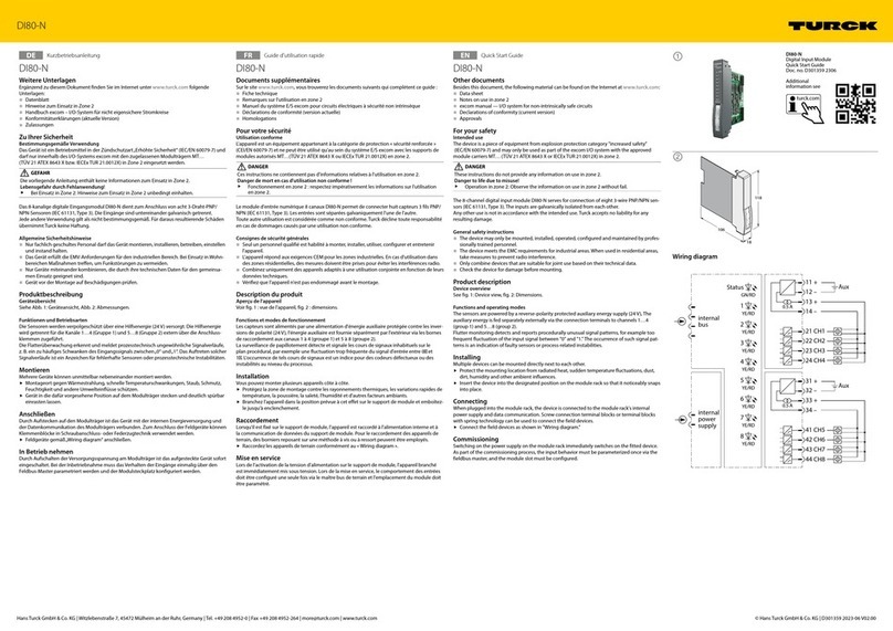
ABB AC 800M User manual

Power and productivity
for a better worldTM
AC 800M
Controller Hardware
System Version 5.1


AC 800M
Controller Hardware
System Version 5.1

NOTICE
This document contains information about one or more ABB products and may include a
description of or a reference to one or more standards that may be generally relevant to
the ABB products. The presence of any such description of a standard or reference to a
standard is not a representation that all of the ABB products referenced in this document
support all of the features of the described or referenced standard. In order to determine
the specific features supported by a particular ABB product, the reader should consult the
product specifications for the particular ABB product.
ABB may have one or more patents or pending patent applications protecting the intel-
lectual property in the ABB products described in this document.
The information in this document is subject to change without notice and should not be
construed as a commitment by ABB. ABB assumes no responsibility for any errors that
may appear in this document.
In no event shall ABB be liable for direct, indirect, special, incidental or consequential
damages of any nature or kind arising from the use of this document, nor shall ABB be
liable for incidental or consequential damages arising from use of any software or hard-
ware described in this document.
This document and parts thereof must not be reproduced or copied without written per-
mission from ABB, and the contents thereof must not be imparted to a third party nor used
for any unauthorized purpose.
The software or hardware described in this document is furnished under a license and
may be used, copied, or disclosed only in accordance with the terms of such license. This
product meets the requirements specified in EMC Directive 2004/108/EC and in Low Volt-
age Directive 2006/95/EC.
TRADEMARKS
All rights to copyrights, registered trademarks, and trademarks reside with their respec-
tive owners.
Copyright © 2003-2013 by ABB.
All rights reserved.
Release: February 2013
Document number: 3BSE036351-510 A

3BSE036351-510 A 5
Table of Contents
About This User Manual
General ............................................................................................................................23
User Manual Conventions ...............................................................................................23
Warning, Caution, Information, and Tip Icons................................................................24
Terminology.....................................................................................................................24
Applicable Specifications ................................................................................................27
EUROPEAN UNION DIRECTIVE COMPLIANCE..........................................27
UL LISTING........................................................................................................27
TÜV Approval......................................................................................................28
Released User Manuals and Release Notes.....................................................................28
Section 1 - Introduction
Product Overview ............................................................................................................29
AC 800M – General .............................................................................................29
PM8xx/TP830 Processor Unit – General.............................................................33
PM891 Processor Unit – General.........................................................................40
PM891/PM86x/TP830 Processor Unit – Redundancy.........................................47
AC 800M High Integrity ......................................................................................50
Control Software ..................................................................................................51
Ethernet Address for PM8xx (Except PM891) ....................................................52
Ethernet Address for PM891................................................................................54
AC 800M Controller – Key Features...............................................................................56
Product Release History ..................................................................................................57
Section 2 - Installation
Site Planning....................................................................................................................59

Table of Contents
63BSE036351-510 A
Site Selection and Building Requirements ..........................................................59
Cables ............................................................................................................62
Power Supply .......................................................................................................63
Enclosures............................................................................................................64
Mounting AC 800M Units onto DIN-Rail ......................................................................65
Mounting on metal sheet......................................................................................66
Prefabricated aluminum profile ...........................................................................67
Installing the PM86x/TP830 Processor Unit in Single Configuration............................78
Installing PM891 in Single Configuration ......................................................................87
Installing the PM86x/TP830 Processor Unit in Redundant Configuration.....................90
Installing the PM891 Processor Unit in Redundant Configuration.................................94
Installing the CEX-Bus without BC810..........................................................................97
Installing the CEX-Bus Interconnection Unit BC810/TP857.........................................97
Installing SM810/TP855 ...............................................................................................104
Installing SM811/TP868 ...............................................................................................107
Installing the PROFIBUS DP Interface, CI851/TP851.................................................111
Installing the FOUNDATION Fieldbus H1 Interface, CI852/TP852............................113
Installing the RS-232C Interface, CI853/TP853 ...........................................................115
Installing the PROFIBUS DP Interface, CI854/CI854A/TP854...................................116
Installing the MasterBus 300 Interface, CI855/TP853..................................................119
Installing the S100 I/O Interface, CI856/TP856 ...........................................................120
Installing the INSUM Interface, CI857/TP853 .............................................................121
Installing the DriveBus Interface, CI858/TP858...........................................................122
Installing the FOUNDATION Fieldbus High Speed Ethernet Interface, CI860/TP860123
Installing the TRIO Fieldbus Interface CI862...............................................................124
Unit to Baseplate Alpha Code Lock ..................................................................124
Bus Termination.................................................................................................124
Installing the Satt I/O Units and CI865 Module ...........................................................126
Installing the Modbus TCP Interface CI867/TP867......................................................127
Ethernet Twisted Pair Connection......................................................................127
Installing the IEC 61850 Interface CI868 .....................................................................128
Installing the AF 100 Interface CI869...........................................................................128

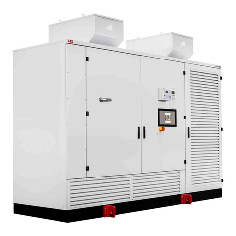
Table of Contents
3BSE036351-510 A 7
3BSE036351-510 A 7
Installing the PROFINET IO Interface CI871...............................................................129
Installing the MOD5 Interface CI872............................................................................129
Installing the EtherNet/IP Interface CI873....................................................................130
Installing the ModuleBus for PM8xx ............................................................................131
Installing the ModuleBus for PM891 ............................................................................132
Installing the SD83x Power Supply...............................................................................133
Installing the Mains Breaker Unit .................................................................................134
Installing the SS823/SS832 Voting Unit .......................................................................136
Installing the SB821 External Battery Unit...................................................................143
Installing the SB822 Rechargeable External Battery Unit ............................................144
Installation of I/O Units.................................................................................................145
Installation in Cabinets ..................................................................................................145
Mounting Dimensions for Proper Ventilation ...............................................................149
Section 3 - Configuration
General Information ......................................................................................................151
Connecting Control Builder ..........................................................................................152
Connection to a Control Network..................................................................................153
Communication Possibilities .........................................................................................154
Controller IP Addresses .....................................................................................157
I/O Systems ...................................................................................................................158
Drive System .................................................................................................................168
Power Supply System....................................................................................................173
Powering Units in the Cabinet ...........................................................................174
Powering Field Equipment outside the Cabinet.................................................174
Powering from an External Source ....................................................................176
Section 4 - Operation
AC 800M Controller (PM8xx) ......................................................................................179
Start-up ..........................................................................................................................182
Start-up in Redundant Configuration (CEX Bus Considerations) .....................182
Start Modes....................................................................................................................183
Automatic Switch-Over to Backup CPU.......................................................................184

Table of Contents
83BSE036351-510 A
Verification of Satisfactory AC 800M Operation..........................................................185
Verification of Single CPU ................................................................................185
Verification of Redundant CPU .........................................................................188
Section 5 - Maintenance
Preventive Maintenance Frequency Schedule...............................................................191
Replacing the Battery....................................................................................................192
Internal Battery ..................................................................................................192
SB821 External Battery Unit .............................................................................195
SB822 Rechargeable External Battery Unit ......................................................197
Online Replacement of Unit..........................................................................................198
Exchange of CPU in Redundant Configuration without BC810...................................199
Exchange of CPU in Redundant Configuration with BC810........................................200
Exchanging a Defect RCU Link Cables Online............................................................202
In Configuration with BC810 ............................................................................202
In Configuration without BC810 .......................................................................202
Corrective Maintenance Procedures..............................................................................203
Fault-Finding Procedures .............................................................................................. 204
PM8xx Processor Unit in Single CPU Configuration........................................204
PM861/PM864/PM865/PM866/PM891 Unit in Redundant Configuration ...... 205
CEX-Bus Interconnection Unit - BC810...........................................................206
SM810/SM811...................................................................................................207
Internal Battery / SB821 External Battery/SB822 Rechargeable External Battery208
PROFIBUS DP – CI851 ....................................................................................209
FOUNDATION Fieldbus H1 – CI852 ...............................................................210
On-board RS-232C Channels – CI853 ..............................................................213
PROFIBUS DP – CI854/CI854A ......................................................................214
MasterBus 300 Interface – CI855......................................................................216
S100 I/O Interface – CI856................................................................................217
INSUM Interface – CI857 .................................................................................218
DriveBus Interface - CI858................................................................................ 219
FOUNDATION Fieldbus High Speed Ethernet - CI860 ...................................221
TRIO Interface - CI862......................................................................................223

Table of Contents
3BSE036351-510 A 9
3BSE036351-510 A 9
Satt I/O Interface – CI865..................................................................................224
Modbus TCP Interface – CI867 .........................................................................225
IEC 61850 Interface – CI868 .............................................................................227
AF 100 Interface - CI869 ...................................................................................228

PROFINET IO Interface - CI871 .......................................................................231
MOD5 Interface - CI872....................................................................................232
EtherNet/IP Interface - CI873 ............................................................................236
Appendix A - Hardware Units
PM851/PM856/PM860 and TP830 – Processor Unit ...................................................239
Technical Data....................................................................................................240
Performance Data...............................................................................................244
PM851A/PM856A/PM860A and TP830 – Processor Unit...........................................245
Technical Data....................................................................................................246
Performance Data...............................................................................................250
PM861/PM861A and TP830 – Processor Unit .............................................................251
Technical Data....................................................................................................252
Performance Data...............................................................................................254
PM864/PM864A and TP830 – Processor Unit .............................................................255
Technical Data....................................................................................................256
Performance Data...............................................................................................258
PM865 and TP830 – Processor Unit .............................................................................259
Technical Data....................................................................................................260
Performance Data...............................................................................................262
PM866 and TP830 – Processor Unit .............................................................................263
Technical Data....................................................................................................264
Performance Data...............................................................................................266
PM891– Processor Unit.................................................................................................267
Technical Data....................................................................................................268
Performance Data...............................................................................................269
BC810 and TP857 - CEX-Bus Interconnection Unit ....................................................270
SM810 and TP855.........................................................................................................273
SM811 and TP868.........................................................................................................278

Table of Contents
10 3BSE036351-510 A
CI851 and TP851 – PROFIBUS DP Interface ..............................................................284
CI852 and TP852 – FOUNDATION Fieldbus H1 Interface.........................................288
CI853 and TP853 – RS-232C Interface ........................................................................292
CI854/CI854A and TP854 – PROFIBUS DP Interface ................................................296
CI855 and TP853 – Ethernet Interface for MasterBus 300...........................................301
CI856 and TP856 – S100 I/O Interface.........................................................................305
CI857 and TP853 – INSUM Interface ..........................................................................309
CI858 and TP858 – DriveBus Interface........................................................................313
CI860 and TP860 – FOUNDATION Fieldbus High Speed Ethernet............................317
CI862 and TP862 - TRIO/Genius Interface ..................................................................321
CI865 and TP865 – Satt I/O Interface...........................................................................328
CI867 and TP867 – Modbus TCP Interface..................................................................332
CI868 and TP867 – IEC 61850 Interface......................................................................336
CI869 and TP869 - AF 100 Interface............................................................................340
CI871 and TP867 – PROFINET IO Interface ...............................................................344
CI872 and TP858 - MOD5 Interface.............................................................................348
CI873 and TP867 - EtherNet/IP Interface.....................................................................352
Power Supply Units – Types SD821, SD822 and SD823 .............................................356
Power Supply Units - Types SD831, SD832, SD833, and SD834................................363
SS822/SS823/SS832 Voting Unit (for Redundant Power Supply) ...............................374
TC562 Modem Unit – (Westermo MD-12DC) .............................................................389
SB821 External Battery – AC 800M Memory Back-up ...............................................392
SB822 Rechargeable External Battery – AC 800M Memory Back-up.........................394
DIN-Rail – TS 35/7.5....................................................................................................396
Miscellaneous Equipment .............................................................................................397
TB850 Terminator for CEX-Bus (Male)............................................................397
TB851 Terminator for CEX-Bus (Female)........................................................399
TB807 ModuleBus Terminator Plug..................................................................400
TB852 RCU Link Terminator Plug....................................................................400
TB853 RCU Control Link Terminator Plug ......................................................400
TK850 CEX-Bus Extension Cable ....................................................................400
TK851 RCU Link Cable....................................................................................400

Table of Contents
3BSE036351-510 A 11
3BSE036351-510 A 11
TK853 ...........................................................................................................401
TK855 RCU Data Link Cable............................................................................401
TK856 RCU Control Link Cable .......................................................................402
TK212A Tool Cable...........................................................................................402
Al-Profile Support For DIN-Rail .......................................................................403
Appendix B - Power Consumption
General ..........................................................................................................................405
Current Consumption and Power Dissipation ...............................................................406
Appendix C - Recommended Components
Recommended Components..........................................................................................411
Appendix D - Directive Considerations
Electro-Magnetic Compatibility (EMC)........................................................................427
Low-Voltage Directive (LVD) .......................................................................................427
Appendix E - Standards
Hazardous Location Approval.......................................................................................429
Appendix F - Environmental Data
Environmental Data for AC 800M Products .................................................................431
Climatic and Mechanical Environmental Conditions ........................................432
CE Compliance ..................................................................................................434
Electromagnetic Compatibility and Main Voltage Conditions ..........................435
Installation Requirements...................................................................................437
Laying Field Cables ...........................................................................................437
Types of Field Cable ..........................................................................................437
DIN-Rail Mounting............................................................................................437
Lightning Protection...........................................................................................438
Inductive Load Suppression...............................................................................438
INDEX

Table of Contents
12 3BSE036351-510 A
Revision History
Introduction ...................................................................................................................449
Revision History............................................................................................................449
Updates in Revision Index A.........................................................................................450

3BSE036351-510 A 13
Safety Summary
General
In order to minimize the risk of injury to personnel and/or damage to the
equipment, always comply with the following safety instructions when
installing and operating an AC 800M Controller system. Local, stricter statutory
regulations must always take precedence over the safety instructions given here.
Warnings and Information Symbols in the Text Margin
Observe the symbols for warnings and information located in other Chapters
and Appendices of this book. The symbols are placed in the left-hand margin,
adjacent to paragraphs requiring special attention. For an explanation of the
symbols, see About This User Manual - Warning, Caution, Information, and Tip
Icons on page 24.
The Safety Instructions are classified as mandatory reading for all suitably
qualified personnel intending to operate the AC 800M Controller.

14 3BSE036351-510 A
Safety Summary
Personnel and Process Safety
A control system is a tool used to control various processes. Responsibility for
attaining and maintaining a satisfactory level of safety rests with the personnel
who engineer, operate and maintain the equipment. It is important to have an
extensive knowledge of all control functions, the inherent safety risks that may
be involved in the process, and to possess the imaginative ability to anticipate
situations in which accidents may occur.
The following Safety Instructions must be observed:
• Take care when:
– fitting or removing units
– connecting or disconnecting cables
– resetting or switching units to manual operation
• For hazardous locations special restrictions apply, see Appendix E,
Standards.
• Never connect the equipment to the mains power supply during installation
work.
• Take extreme care when connecting the system to the mains power supply.
Injury or death can be the result of incorrect procedures.
• Ensure that all personnel operating or maintaining the installation know the
exact location of and how to operate the equipment isolating safety switch
and the mains power supply isolating switch.
• When the process sub-sections have been checked and a test run has been
performed, a person responsible must check the interlocking chains etc. All
concerned personnel must be fully informed regarding test runs to be
performed.
TAKE CARE AT ALL TIMES – This will prevent accidents from
occurring and help protect valuable equipment.

3BSE036351-510 A 15
Safety Summary (continued)
• Process technicians are to be present when testing and operating process
objects.
• Never activate any System Initialization push-button if any uncertainty
exists regarding exactly what occurs within the system during initialization.
ALWAYS CHECK FIRST.
• Remember at all times, that the control system can be controlled from a
remote engineering station, connected at another node via Control
Network.
• Remember, the AC 800M Controller will start automatically when voltage
is applied.
Taking steps to bring the process to a safe state, provides an improved level of
safety when power supplies, communication links or parts of the control system
fail. Such steps may require, for example, the installation of valves or relays that
automatically return to a fail-safe position.
Product Safety
The following safety rules must be observed at all times:
• To avoid discharging static electricity, ground both yourself and any tools
before handling printed circuit boards, batteries, memory cards, and other
sensitive pieces of the equipment
• All electronic devices are sensitive to ESD (electrostatic discharge). To
avoid accidental damage while handling printed circuit boards, it is
recommended to wear a wrist strap, grounded to the chassis. The strap must
have a built-in protective resistor
• Anti-static, conductive plastic bags must be used for storage and transport
of PC boards in transit.

16 3BSE036351-510 A
Safety Summary
Before replacing Units
Maintenance
All procedures for replacing units can be located by referring to the relevant
documentation.
Removing or replacing units with system power connected can cause injury to
personnel and damage to equipment. It is, therefore, of the utmost importance
that the power supply be fully disconnected, on the process side, before removal
or insertion of units takes place.
See Online Replacement of Unit on page 198 and I/O documentation.
It is recommended that a stock of suitable spare components be maintained to
avoid system downtime.
Ensure that back-up copies of the current application program are made at
regular, predetermined intervals to avoid system downtime.

3BSE036351-510 A 17
Safety Summary (continued)
Operating Environment
Before the AC 800M Controller system is brought online, investigate which
environmental conditions are applicable. Take note in particular of the
following:
• The controller must not be exposed to conditions that exceed the values given
in the relevant technical specifications.
• The controller must not be used in an environment exposed to strong electrical
interference. Electrical machines can produce interference that exceeds levels
permitted for the equipment, for example during repair work.
• All products must be handled with appropriate precautions with regard to
electrostatic damage.
• The controller must not be exposed to direct sunlight.
Important Software Check
• Use the system’s fault-monitoring facilities to prevent accidents or mishaps.
• When in doubt, ALWAYS CHECK before executing changes.
Important Hardware Notice
•DO NOT, under any circumstances, disconnect the power supply to a
normally functioning system. Always use the correct system shut-down
procedure prior to disconnecting the power supply.
Signal Noise Due to Cables
Cables which may cause electrical interference (for example, power supply cables)
must not be installed adjacent to bus cables carrying fast digital signals. Ensure that
a minimum distance of 10 cm (4 in.) is provided between cables installed inside
cabinets.
Hazardous Electrical Supplies
Operational and maintenance procedures, during which personnel may come into
contact with high voltage, should only be carried out by personnel fully trained in
the maintenance of electrical equipment within those environments, and who are
fully aware of all risks involved.

18 3BSE036351-510 A
Safety Summary
Electrostatic Sensitive Device
Devices labeled with this symbol require special handling precautions as
described in the installation section.
GENERAL
WARNINGS
Equipment Environment
All components, whether in transportation, operation or storage, must be
in a noncorrosive environment.
Electrical Shock Hazard During Maintenance
Disconnect power or take precautions to insure that contact with ener-
gized parts is avoided when servicing.
SPECIFIC
WARNINGS
Page 67: The AC 800M Controller and associated units must be unpow-
ered and disconnected when being mounted onto a DIN-rail!
Page 68: It is not allowed to manipulate CEX bus baseplates in a powered
and running system. Before changing or removing a baseplate, all CEX
modules on that segment must be removed.
Page 72: AC 800M units must be disconnected from the power source
before removing them from a DIN-rail!
Page 72: It is not allowed to manipulate CEX bus baseplates in a powered
and running system. Before changing or removing a baseplate, all CEX
modules on that segment must be removed.
Page 78: For PM861/PM864/PM865/PM866 insert the RCU Link Termi-
nation plug TB852, at the RCU Link connector. The termination plug must
always be used for PM861/PM864/PM865/PM866 when running in single
configuration. When a redundant processor is running in a single configu-
ration use the RCU Link Cable TK851, if the RCU Link Termination plug
TB852 is not available.

3BSE036351-510 A 19
Safety Summary (continued)
SPECIFIC
WARNINGS
(continued)
Page 124: The CI862 baseplate has no locking device. Insert only the
CI862 unit into this baseplate. Insertion of other unit types may cause
damage to the equipment.
Page 191: Before attempting maintenance or troubleshooting, read the
Safety Summary on page 13. Failure to do so could lead to personal
injury or damage to equipment.
Page 198: It is not allowed to manipulate CEX bus baseplates in a pow-
ered and running system. Before changing or removing a baseplate, all
CEX modules on that segment must be removed.
Page 429: Explosion hazard - Substitution of components may impair
suitability for Class I, Zone 2.
Page 429: Explosion hazard - Do not replace batteries unless the power
has been switched off or the area is known to be non-hazardous.
Page 430: Explosion hazard - Do not disconnect equipment unless the
power has been switched off or the area is known to be non-hazardous.
SPECIFIC
CAUTIONS
Page 68: To prevent damage to the pins, be sure the baseplate plugs and
sockets are fully aligned as the units interconnect. Under no circum-
stances use excessive force!
Page 68: It is essential that the locking device be placed in the LOCKED
position to avoid possible problems caused by vibration and/or intermittent
grounding.
Page 73: In order to provide adequate access and removal space, note
that the SLIDE sequence must be carried out on the unit baseplates adja-
cent to the unit that is to be removed.
Page 73: The unit baseplates are easily disconnected from each other by
gently prying them apart with a blade screwdriver (see Figure 23 on page
74).

20 3BSE036351-510 A
Safety Summary
SPECIFIC
CAUTIONS
(continued)
Page 76: Do not manipulate the locking device. ABB will take no responsi-
bility for errors caused by manipulating locking devices.
-79 and Page 92: Do not place the internal back-up battery in the battery
holder until the AC 800M Controller has been powered-up normally and
the memory back-up function has been activated, that is, the B(attery)
LED flashes. If no normal power supply is connected to the processor unit
with the battery in place, then the CPU memory will immediately start to
consume battery power.
Page 90: Note that in redundant CPU configuration, COM3 and the electri-
cal ModuleBus on the baseplate can not be used.
Page 91: Note that the RCU Link Cable TK851 must be used and can not
be replaced by a similar cable. Using another cable will disable the identi-
fication of the CPUs in the CB and Operator Station. When running in sin-
gle configuration the RCU Link Cable TK851 might temporarily be used to
perform the function of a termination plug.
Page 98: Do not connect the two CEX-Bus segments, separated with
BC810, to each other with CEX-Bus extension cable TK850.
Page 98: In AC 800M High Integrity Controllers it is required that the exter-
nal supply input of BC810 is connected and that the power supply is
strictly configured either according to Figure 33 or according to Figure 34
and nor is it allowed to change the configuration by way of for instance
individual circuit breakers between modules.
Page 99: Hot swap of the BC810 located next to a primary or single con-
troller CPU, otherwise called “direct BC810”, might jeopardize the whole
controller and should not be performed unless every module on the
CEX-Bus are in a non-operating state. Note: In an AC 800M HI controller
this is unconditionally and intentionally leading to a shutdown of the con-
troller.
Page 112: It is not possible to change the CI851 unit via hot swap and it is
not allowed to perform an online upgrade of firmware in a system contain-
ing CI851.
Other manuals for AC 800M
5
Table of contents
Other ABB Industrial Equipment manuals
Popular Industrial Equipment manuals by other brands

Mathey Dearman
Mathey Dearman 2SA Parts and Operating Manual

MK Products
MK Products CobraTurn T-260 owner's manual

ProMinent
ProMinent Sigma SIBa operating instructions

SCHUNK
SCHUNK VERO-S NSE3 138-V1 Assembly and operating manual

Pfeiffer Vacuum
Pfeiffer Vacuum MPT 200 operating instructions

Climax
Climax BF-R operating manual

Epiroc
Epiroc 140T Safety and operating instructions

KTR-Group
KTR-Group ROTEX AFN-SB spec. Operating & assembly instructions

Chentronics
Chentronics SureSpark LO-2 Installation and operation manual

Dungs
Dungs VDK 200 A S02 instructions

Becker
Becker SV 500 operating instructions

Siemens
Siemens MICROMASTER 440 Getting started guide