11.
Arc fault detection
TRIO-TM-60.0-US-480-Quick Installation Guide EN-RevA
EFFECTIVE 2018-02-06
© Copyright 2018 ABB. All rights reserved.
Specications are subject to change without notice.
6.
Output connection (AC)
Assembly instructions (continue)
Contact us
www.abb.com/solarinverters
Conrm the PV array’s input polarity is correct.
Conrm the PV array has no ground leakage current.
The DC disconnect switch disconnects the DC current from the PV panels in the “OFF” position. The inverter will stop producing power,
but DOES NOT disconnect the AC from the grid. To prevent electrocution hazards, all the connection operations must be carried out with
the external AC disconnect switch (grid side) of the inverter open and locked out.
The transformerless design of the inverter requires that the PV array to be oating with respect to ground per NEC 690.35.
Per NEC 690.35, wires from the PV array must be UL-listed, 1000V minimum rating, 90°C minimum temperature rating.
The inverter equipped with DCWB-2 and DCWB-3 versions have three input channels (thus beneting from three trackers for MPPT maximum power point tracking)
which work independently of one another, which can be paralleled by leveraging a single MPPT.
The independent conguration of the input channels (MPPT) is set at the factory. This means that the parallel bar (supplied) is not be installed on the parallel MPPT
connection points
55
, and that the software setting “Independent channel mode” is performed on the inverter.
If is necessary to put the 3 input channels in parallel, the parallel bar (supplied) must be installed on the parallel MPPT
connection points
55
, and that the software setting “parallel channel mode” should be performed on the inverter; this
setting can be done by different way:
1. During the commissioning wizard phase (STEP 4)
2. In the dedicated section of the internal webserver “Setup section > Setup DC side > Input mode”
To install the parallel bar follow the procedure below:
- Place the parallel bar (supplied) on the connection points
- Install the 3 screws with washers supplied (torque 4Nm / 3.0 ft-lb)
The PV array equipment ground wire(s) must be connected to the equipment ground terminal
block (labelled “EGC”) in the DCWB.
DCWB-1 model: EGC terminal block accept 3 wires 4AWG to 0AWG (copper or aluminum).
Torque to 14Nm (10.3 ft-lb).
DCWB-2 and DCWB-3 model: EGC terminal block accept 6 wires 6AWG to 4AWG
(copper). Torque to 14Nm (10.3 ft-lb).
+IN-IN
EGC
ATTENTION
UTILISEZSEULEMENTCÂBLESEN CUIVRE OU ALUMINIUM 75 °C OU 90 °C.Consultez le
manueld'instructionspourla tailledes ls approprié (AWG)et pour couplesde serrage
àappliquerauxbornesdecâblage.
CAUTION
USE75°COR90°CCOPPERORALUMINIUMWIREONLY.Refertotheinstructionmanualfor
suitablewiresize(AWG)andfortighteningtorquetobeapplied tothewiringterminals.
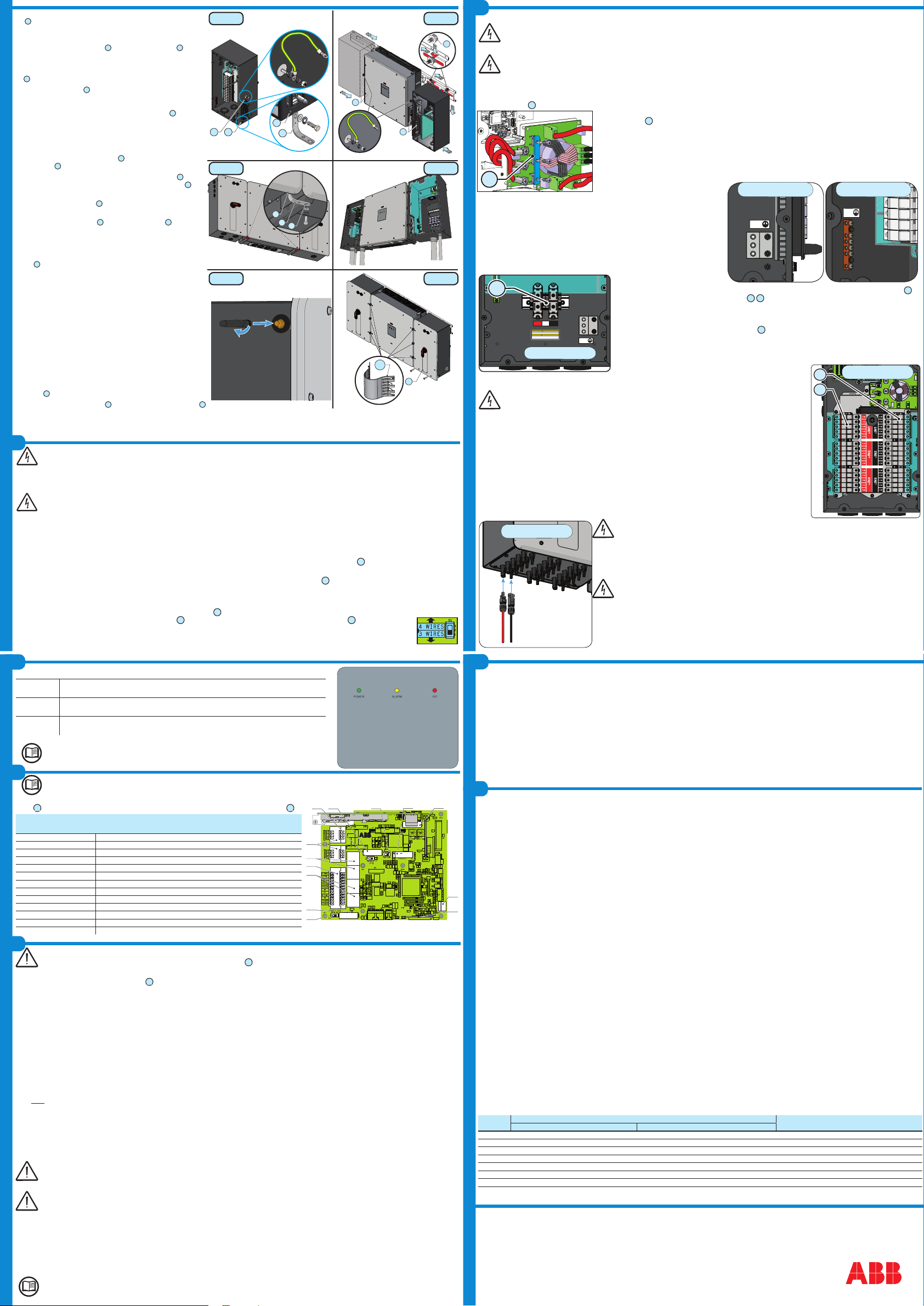
13
DCWB-1
DCWB-1 model:
In this model of DCWB the PV array is connected to the inverter through the DC input terminal block
13
by
inserting the cable into the DC conduit openings
16
19
.
- Conrm the DC cables are 4AWG - 3/0AWG, copper or aluminum.
- Run the DC cable through the conduit openings
- Connect PV array to the the DC input terminal block
13
(+ and -).
- Torque screws to 14 N-m (10.3 ft-lb).
- When nished, go back and conrm the polarity is correct for each
string.
- Give each wire a pull test to conrm the connection is secure.
DCWB-2 model:
-2 models have fuse holders for each individual string conductor. 15 string inputs are available.
DCWB-2 model have fuse holders for each individual string conductor pair.
Fuses are sized for single-string currents only. Strings may be not paralleled in the PV array.
- Conrm the DC cables are 12 AWG to 3 AWG.
- Conrm that strings are not paralleled in the PV array.
- Conrm that the string fuse size is below 20A
- Insert the DC conductors through the opening.
- Connect each string to the appropriate fuse holders (+ and -) following site wiring diagrams. The input fuse holder are
divided into 3 groups (one group for each input channel) consisting of 5 pairs of quick t connectors
Positive fuse 1 (+) is the top left. Negative fuse 1 (-) is the top right.
- Torque screws to 3.4Nm (30 in-lb).
- When nished, go back and conrm the polarity is correct for each string.
- Give each wire a pull test to conrm the connection is secure.
- Conduit must be attached using liquid tight ttings to maintain Type 4 enclosure integrity.
DCWB-3 model:
-3 models have fuse holders for each individual string conductor. 15 string inputs are available.
DCWB-3 model have string fuses for each individual string conductor pair.
Fuses are sized for single-string currents only. Strings may be not paralleled in the PV array.
- Conrm the DC cables are 12 AWG to 3 AWG.
- Conrm that strings are not paralleled in the PV array.
- Conrm that the string fuse size is below 20A
- Install the quick t connectors on the string cables.
Depending on the model of the connector of the inverter, it is necessary to use the same model and the
respective counterpart. Refer to the document “String inverter – Product Manual appendix” available
at www.abb.com/solarinverters to know the brand and the model of the quick t connector.
Using corresponding parts that are not compliant with the quick t connector models on the inverter
could cause serious damage to the unit and void of the warranty.
- Connect each string to the quick t connectors located on the bottom of the DCWB, following site wiring diagrams.
The input connectors are divided into 3 groups (one group for each input channel) consisting of 5 pairs of quick t connectors
- When nished, go back and conrm the polarity is correct for each string.
- Give each wire a pull test to conrm the connection is secure.
- Conduit must be attached using liquid tight ttings to maintain Type 4 enclosure integrity.
3711 32
37
27
23
23
08
29
15.
Attach the two green/yellow ground wires to the attachment points
11
on each wiring box with the M6 lock washer and the M6 nut which
are shipped with the inverter (torque to 11Nm or 8ft-lb). Let the loose
end of the cable hang downwards. (FIG. 6)
16. Attach the two ground brackets
32
to the attachment points
37
on each
wiring box with the M6 at washer, M6 lock washer and the M6 hex screw
which are shipped with the inverter. Let the screws loose and not tightened.
The bracket is not symmetrical. When you install it in the attachment point
37
, make sure that the side with 2 holes is facing downwards. (FIG. 6)
17.
Insert the rear studs
27
on top of rst wiring box into the bracket
slots. Then do the same with the other wiring box. This way, the
wiring boxes will be somewhat detached from the power module,
so that they won't interfere with the quick disconnects
23
. (FIG. 7)
18.
Attach the wiring box ground cable to the converter module with
the following hardware stackup: lock washer, ground cable, lock
washer and hex nut (torque to 11Nm or 8ft-lb).
(FIG. 7)
19.
Attach the power module to the wiring boxes one at a time by sliding
them horizontally onto the bracket
01
and make sure that the quick
disconnect
23
are correctly inserted. (FIG. 7)
20.
Once coupling has been completed, the metal locking fork
07
must be
installed into the appropriate seats on the quick disconnects
23
. This
way, the wiring boxes get mounted to the power module.
21.
Insert the stabilization fork
28
into the guides and block the screw on
the caged nuts previously mounted on the bracket.
22.
Attach the ground brackets
32
in the mounting points
37
on the lower
side of the conversion module with the M6 at washer, M6 lock washer
and the M6 hex screw which are shipped with the inverter (torque to
11Nm or 8ft-lb). (FIG. 8)
23. Torque the two screws (one for each wiring box) on the 2 ground brack-
ets
32
(torque to 11Nm or 8ft-lb)
. (FIG. 8)
24.
Remove the plug and install the conduit on the bottom side of the
ACWB and DCWB (-1 and -2 models). (FIG. 9)
Use FMC (Flexible Metal Conduit) for the nal two to three feet con-
necting to the inverter so that the inverter can be installed easily.
All conduits must be attached using liquid-tight ttings to maintain UL
50 NEMA Type 4X enclosure integrity.
The input connection on DCWB-3 is made on the external quick-
t connectors and conduits are not present.
25.
Run the AC, DC and low voltage cables through the opening(s).Only in
the DCWB-3 the input connection is made on the external connectors.
26.
Remove the protective cover from the support of the wireless an-
tenna located on the left side of the DCWB. Install the wireless
antenna by screwing it into the specic connector. (FIG. 10)
27.
When wiring is complete,
close the key locks and
attach the front
covers
08
to the two wiring boxes (8 screws each).
28.
Install the 6 conducting springs
29
between the power module cover
03
and the wiring box covers, in the unpainted areas. (FIG. 11)
FIG 7
FIG 9
FIG 11
FIG 6
FIG 8
FIG 10
To prevent electrocution hazards, open and lock out the external AC disconnect switch before connecting the AC conductors, and any
time the AC wiring box cover is to be removed. Proper PPE is required.
Caution! Connect the ground before starting the grid connections.
AC output overcurrent protection is not provided with the inverter; it is the responsibility of the end user to provide overcurrent
protection for the AC output circuit. To reduce the risk of re, connect only to a circuit provided with an overcurrent protection in
accordance with the NEC (ANSI/NFPA 70). The inverter must be connected only to a dedicated branch circuit provided with the maximum
branch overcurrent protection device (OCPD); the maximum acceptable current rating is 100 Amps.
Keep the resistance of the wires to a minimum between the OCPD and the AC terminals, to ensure the correct work of the protective devices.
Size conductors per NEC Article 310 -- use 90°C wire only; conductors must be sized according to operating temperature range and
continuous current ratings. The AC grid wiring is connected through the inverter wiring box.
AC output wire must be UL listed wire rated minimum 600V.
The inverter can be connected to the grid through a three-wire or a four-wire connection.
Standard and ACWB- A models:
- AC conductors (4AWG to 3/0AWG, copper or aluminum, torque to 20Nm / 14.7 ft-lb) will be connected to a terminal block
17
inside the AC wiring box.
ACWB-B model:
- AC conductors (8AWG to 1/0AWG, copper, torque to 6Nm / 53in-lb) will connect to the AC disconnect switch
36
inside the AC wiring box. The AC disconnect
switch is designed for copper wire. If aluminum wire is used, terminate the aluminum wire with a bi-metallic terminal.
AC cable installation:
- Run the AC cables through the opening(s).
- Connect the ground cable to the protective earth (PE) connection point
20
.
-
Connect the grid conductors to the AC output terminal block
17
in the Standard / -A models or directly to the disconnect switch
36
in the -B wiring box.
- Give each wire a pull test to conrm the connection is secure.
- Set the switch on the AC lter board, based on the grid connection conguration: choose 3WIRES for WYE connection w/o N wire (L1+L2+L3+GND)
or 4WIRES for WYE connection with N wire (L1+L2+L3+Neutral+GND).
7.
Input connection (DC)
For DCWB-1 model the Arc Fault Circuit Protection required by NFPA 70 Article 690.11 must be provided in the combiner box feeding the inverter.
For DCWB-2 and DCWB-3 models only, the AFD performs a self-test when the system is started.
- If the self-test results are OK, the inverter will continue to AC grid connection.
- If a potential problem on the AFD board is detected, the self test will result in error E053.
Refer to the product manual (downloadable as described on the cover page) for troubleshooting suggestions.
During normal operation the input current is continually measured and analyzed.
- If a DC arc fault is detected during operation, the inverter is disconnects from AC grid and generates an E050 error code (readable through internal Webserver).
- Press and hold the AFD reset button on the left side of the DC wiring box for 3 seconds. This will clear the E050 error and restart the self test.
- If self-test results are OK, the inverter will reconnect to the AC grid; if the DC arc fault is still present, the self-test will result in error E053. Refer to the product manual
online for solutions. The AFD self-test can be manually started anytime using the following procedure:
1. Turn off the inverter (switching off both DC and AC switches),
2. Turn on both the DC and AC switches and wait for self-test result.
If the AFD trips frequently, it means arcs are occurring. Turn the inverter OFF and request service to do complete check of the system wiring, including all connections
and junction boxes, to locate the problem.
The inverter can also be installed horizontally using the horizontal installation bracket. Horizontal installation instructions are described in the product manual
available at
www.abb.com/solarinverters (select appropriate country location on website).
12.
Grid support functions and
Voltage & Frequency trip limits
The inverter is equipped with advanced grid support functionality that is useful to support reactive loads and also assist in reliable operation of the utility grid in the presence
of a large number of distributed energy generation sources. The grid support functions that are equipped on this inverter are described in the following sections.
The internal Webserver can be used to adjust grid parameters. A Wi-Fi connection to the inverter is required to modify settings using the internal Webserver.
This QIG provides an overview of the available grid support functions. For complete details, refer to the product manual at www.abb.com/solarinverters.
1. Voltage ride-through
This inverter provides parameters to respond to undervoltage and overvoltage events. The inverter is designed to operate normally within the specied operating range. If
voltage excursions occur, the inverter is designed to continue operating normally or cease to export power for a specied delay. Beyond this programmed delay, the inverter
disconnects from the grid in the event of an abnormal voltage condition.
2. Frequency ride-through
This inverter provides parameters to respond to underfrequency and overfrequency events. If frequency excursions occur, the inverter is designed to continue operating
normally for a specied delay. Beyond this programmed delay, the inverter disconnects from the grid in the event of an abnormal voltage condition.
3. Reactive power control
The inverter provides several modes of operation for reactive power control and are described below:
- Disable: This is the default setting. Under this setting, the inverter exports with a power factor of 1.0.
- Fixed power factor control (Cosɸ set): In this mode, the operator can set the output power factor to a xed value. When enabled, a new value will be set in the inverter.
- Q Fixed (Q Set): Sets the reactive power to a xed value. When enabled, a new value will be set in the inverter.
- Power factor as function of output power (Watt/Cosφ Settings: Cosφ(P)): In this mode, the inverter reduces the power factor (cos-phi) as a function of the output
power at a given operating point. The 4 points of the default curve, where you can set the % of Pmax values and related cos-phi, can be modied using the internal
Webserver. When enabled, the curve will be set in the inverter.
- Dynamic Volt/VAR control (Volt/VAr Settings: Q(V)): Under this mode, the level of reactive power exported by the inverter is a function of the operating grid voltage,
also known as a Volt/VAR curve. The 4 points of the default curve, where you can set the % of Vnom values and related % of Smax, can be modied using the internal
Webserver. When enabled, the curve will be set in the inverter.
4. Active Power Control
This inverter offers several modes for active power reduction.
- Active Power Curtailment: Sets a new value of active power as % of Pmax. When enabled, a new value will be set in the inverter.
- CEI Average VGrid Derating (only italian grid standard): Sets, after a specic threshold, an active power derating based on the average of Vac on 10 minutes as per
CEI-021 italian grid standard.
- Volt/Watt settings: P(V). Under this mode, the level of active power exported by the inverter is a function of the operating grid voltage, also known as a Volt/Watt curve.
The 4 points of the default curve, where you can set the % of Vnom values and related % of Pmax, can be modied using the internal Webserver. When enabled, the
curve will be set in the inverter.
- Frequency/Watt function (Frequency Control: P(f)): In this mode, the inverter limits the active power as a function of the grid frequency.
5. Ramp control
The inverter is designed to control the rate at which output power is increased, either at startup, or after a temporary low power condition on the PV array (such as fast
shading). The following ramp controls are provided on this inverter.
- Normal ramp: The normal ramp denes the maximum rate at which the inverter can increase the output power under normal operation. The normal ramp control limits
the uctuations in the output power in order to prevent instabilities on the utility grid.
- Soft start: The soft-start ramp denes the maximum rate at which the inverter can increase the output power when the inverter is rst starting up. This startup may occur
on a daily basis or when the inverter restarts after an abnormal grid event has ended.
This inverter has been factory programmed to automatically disconnect from the utility distribution system in compliance with UL 1741 and IEEE 1547-2003
specications. Default voltage and frequency trip limit and trip time settings to comply with these standards are shown in table below. The internal Webserver
can be used to adjust Voltage and Frequency Trip Limit and Trip Time Parameters according to Grid requirements of installation country.
Condition Utility source Max. time (sec) at 60Hz before cessation of
current
Voltage (V) Frequency (Hz)
A < 0.50 Vnom (Fixed) Rated (60Hz) 0.16 (default)(Adj. Set Points 0.16 to 50s)
B 0.50 Vnom ≤ V < 0.88 Vnom (Adjustable) Rated (60Hz) 2 (Default)(Adj. Set Points 0.16 to 100 sec)
C1.10 Vnom < V < 1.2 Vnom (Adjustable) Rated (60Hz) 1 (Default)(Adj. Set Points 0.16 to 100 sec)
D1.2 Vnom ≤ V(Fixed) Rated (60Hz) 0.16 (Adj. 0.001 to 0.16s)
E Rated f > 60.5Hz (Default)(Adj. 60.1 to 66.0 Hz) 0.16 (Default) (Adj. Set Points 0.16 to 1000 sec)
F Rated f < 59.3 Hz (Default)(Adj. 50.0 to 59.9 Hz) 0.16 (Default) (Adj. Set Points 0.16 to 1000 sec)
G Rated f << 57.0 Hz (Default)(Adj. 50.0 to 59.9 Hz) 0.16 (Default) (Adj. Set Points 0.16 to 1000 sec)
H Rated f >> 63.0 Hz (Default)(Adj. 60.1 to 66.0 Hz) 0.16 (Default) (Adj. Set Points 0.16 to 1000 sec)
Reconnection 300s (Default) (Adjustable 20s to 1000s)
55
DCWB-2/3DCWB-1
DCWB-2
9.
Comm. and Control Signal
8.
Instruments
10.
Commissioning
See the manual for details on the connections and functions available on the communication and control board.
The table shows the main components and connections available on the communication and control
board
09
. Each connection cable reaches the communication board through service cable glands
35
.
Board
Screen-
Printing
Reference Description
A5 a04 SD CARD housing
J5 - J6 a09 Connection to the multifunction relay (ALARM and AUX)
J7 a11 RS485 serial connection; 5V auxiliary, remote ON/OFF
S6 a12
Switch for setting the termination resistance of the RS485 line (1)
S5 a13
Switch for setting the termination resistance of the RS485 line (2)
J9 - J10 a14 Connection of the RS485 line (1) on RJ45 connector
J8 a15 RS485 communication board slot (1)
J11 - J12 a16 Connection of the RS485 line (2) on RJ45 connector
J16 a17 RS485 communication board slot (2)
S7 a18
Switch for setting the inverter to normal or service mode
J22 a19 Inverter data memory card slot
X5 a20 Battery housing
J1 a22 Grounding Kit housing (optional)
Description of the LEDs located on the Power Module cover:
POWER LED
GREEN On, if the inverter operates correctly. Flashes in the network control phase or if the sunlight
is not enough.
ALARM LED YELLOW The inverter has detected a fault.
For inverters with a display, the error/warning message appears on the display.
GFI LED RED Ground fault of the PV array, DC side.
For inverters with a display, the error message appears on the display.
Refer to the product manual for a description of error/warning codes.
Before starting the inverter commissioning procedure, ensure that all the checks indicated in the previous sections of this Quick Installation
Guide have been correctly performed and also that the front covers
08
have been correctly re-installed!
The inverter can be commissioned and congured from a wireless device, such as a Smartphone, a tablet or a laptop. The commissioning procedure is as follows:
1. Put the DC disconnect switch of the inverter
14
or any external DC switch in the “ON” position; if the voltage supplied to one of the input channels is greater
than the minimum power-up voltage, the inverter will turn on. The inverter is powered ONLY by the voltage supplied by the PV array; the presence of
grid voltage alone IS NOT SUFFICIENT to allow the inverter to power up.
2. Enable the wireless functionality on the device you are using for the commissioning of the inverter (tablet, Smartphone or PC) and connect the device to
the access point created by the inverter. The list of available networks will show a network named ABB-XX-XX-XX-XX-XX-XX, where “X” is an hexadecimal
number of the MAC Address (the MAC Address is indicated on the “wireless identication label” on the side of the inverter).
3. When prompted, type the "product key" (including the dashes. Example: 1234-1234-1234-1234) as the network password to access the inverter's access
point. The product key is printed on the “wireless identication label”on the side of the inverter.
4. Open your Internet browser and enter the default IP Address to access the Conguration Wizard page: 192.168.117.1 (this address will always be active and
usable to access, at any time and in any mode of operation of the inverter, the internal Web server).
5. This will start the Conguration Wizard, which runs of a number of conguration steps. During these steps, you will prompted to enter the appropriate
information in each relevant eld (the language for the Conguration Wizard can be changed on the upper status bar). During the procedure you will be
prompted for the following information:
- STEP 1 - Set the Admin/User access credentials (at least 8 characters for the password). Username and password are CASE SENSITIVE.
- STEP 2 (OPTIONAL) - Enter the required information (IP Address selection mode, SSID, and password) to connect the inverter to the wireless network
in (Note: This step can be skipped if you do not want to connect the inverter to a router or if the inverter is connected to the router via ethernet connection).
Once the connection between the inverter and wireless home network is established, a new message will be displayed showing the IP Address assigned by
router to the inverter for ensuring access to the internal Web server. TAKE NOTE OF THE LINKS (refer to the product manual for further information on the
internal Web server features).
- STEP 3 - Set the Date, Time and Time Zone (the inverter will display these input elds when available).
- STEP 4 - Set the inverter country standard and Input channel conguration.
By clicking “FINISH” the wizard completes the conguration procedure (after the settings are conrmed, the inverter restarts).
From the moment the grid standard is selected, there will be 24 hours available to make any changes to the grid standard; after this, the
"Country Select” feature is blocked and you can make further changes only by resetting the remaining-time timer. To select a new grid
standard, you must reset the remaining time, by logging in to the internal web server with Admin Plus rights. Admin Plus access is done via
a unlocked Token calculated at https://registration.abbsolarinverters.com.
Any inverters installed, or commissioned, in California after September 8, 2017 must be set to the Rule 21 country code
USA (RULE21) - Three Phase/60Hz.
6. Put the external AC disconnect switch downstream of the inverter to the “ON” position. Once the AC and DC disconnect switches are closed and the
Conguration Wizard has completed the conguration procedure, the inverter starts the grid connection sequence; the inverter measures the grid voltage and
the ground insulation resistance of the PV eld, and performs other automatic checks. During the preliminary checks in parallel with the grid, the "Power" LED
is ashing, while the other LEDs are off. If the sunlight is not sufcient to ensure connection to the grid, the inverter will repeat the connection procedure until
all grid connection parameters fall within the expected value range.
If the outcome of the preliminary checks is positive, the inverter will connect to the grid and start exporting power. The “Power” LED remains solid on, while the
“Alarm” and “GFI” LEDs are off.
For more information about the conguration and use of the internal Web server, refer to the product manual.
S6
ON OFF
J1
J18
J7 J5
J8
X5
J6
J9 J10 J11 J12
J16
a04
a22
a19a20
a14
a16
a09
a17a13 a18
a12
a15
a11
DCWB-3


