15.
Commissioning
12.
Set grid standard
13.
Communication wiring
16.
Characteristics and technical data
14.
User interface
UNO-2.0-2.5-I-OUTD-S-US Quick Installation Guide
BCM.00226.0_AA
© Copyright 2014 ABB. All Rights Reserved.
Specications subject to change without notice.
9.
DC input grounding
Grounding of inputs is negative conguration by default.
• Grounding cable a02 is located in the inverter on the main board.
• It is connected in position a03 for negative grounding of the inputs as illustrated below.
• To change the grounding to positive, move the connector installed in position a03 (negative) to position a04 (positive).
• In addition to moving the connector, it is also necessary to reverse the internal DC connection cable positions 4 and 6, found on the DC terminal
block within the switchbox as shown below right.
Negative ground conguration (default)
DC connection cable positions
4 (negative) and 6 (positive)
Positive ground conguration
DC connection cable positions
4 (positive) and 6 (negative)
Ground cable connector a02 and
input positions a03 (negative)
and a04 (positive)
10.
DC input connections
DC input connection depends on the grounding
conguration.
DC input connections are made after connecting an
appropriate raceway to the chassis, pulling the conductors
through the raceway and DC cable openings 18, and
connecting them to the DC terminal block 14.
In the switchbox, connect the DC input cables from the PV
string to the DC input terminal block 14 as follows:
NEGATIVE GROUNDING POSITIVE GROUNDING
Position 4: Negative input
pole of the PV array
Position 5: Positive input
pole of the PV array
Position 4: Positive input
pole of the PV array
Position 5: Negative input
pole of the PV array
11.
AC output connections
DC switch 07 disconnects PV array current from the inverter when
switch is in the OFF position. It DOES NOT disconnect AC from the grid.
To disconnect the inverter from the AC grid, an external, customer
supplied AC switch must be used.
• Connect the AC wires on the inverter AC terminal block (positions 1, 2, 3)
based on the utility voltage conguration table below.
• Illustration at right shows the AC connection using AC cable openings 19 and
AC terminal block 16.
• Dotted line indicates where additional wire can be connected if used.
4 5 6 1 2 3
FUSE
19 16
1 2 3
Set the grid/country standard using the two rotary switches found on the main board in the inverter prior to connecting the inverter to the
distribution grid.
Before turning the rotary switches conrm the inverter is switched OFF!
• Refer to selections below for the appropriate choice of grid parameters.
• Default setting 0 / 0 means no grid standard is selected and display language is English.
(“Set Country” message will appear on the inverter display).
• Turn dials of two rotary switches a09 to program the selected grid settings.
• Settings become xed after 24 hours of operation (the inverter does not need to be connected to the
grid, but only needs DC power to count operation time).
• Time remaining can be seen in the menu, and a notice appears on the display if time has expired.
• Contact technical
support with part number
and serial number of
the inverter to change
standard after settings
have been xed for 24
hours.
RS485CARD
J24
RS485(B)
17
1
18
J15
1
J16
2
J6
1
RS485
T/R
T/R
RTN
LNK
J14
BT1
CR2032
WIND
REM
WT
WT
R
R
RS485(A)
J13
ALARM
N.C.
N.O.
C
TERM.120
ON
OFF
S3
17
MEMORYCARD
J4
18
K4
J23
S1
1
S2
2
N
1
L
2
MOV3
3
MOV4
J25
RED
GFI
GFI
BLACK
W4
W3
WHITE
GND_MODE
W2
GRID
MOV2
J10
3
+IN
4
J20 F1
J5
1
5
2
9
6
14
11
J9
DCIN
-IN
1
-IN
2
J19
J7
1
MOV1
+IN
J17 J18
J8
1
a09
Top
Bottom
0
1
2
3
4
5
6
7
8
9
A
B
C
D
E
F
0
1
2
3
4
5
6
7
8
9
A
B
C
D
E
F
0
1
2
3
4
5
6
7
8
9
A
B
C
D
E
F
0
1
2
3
4
5
6
7
8
9
A
B
C
D
E
F
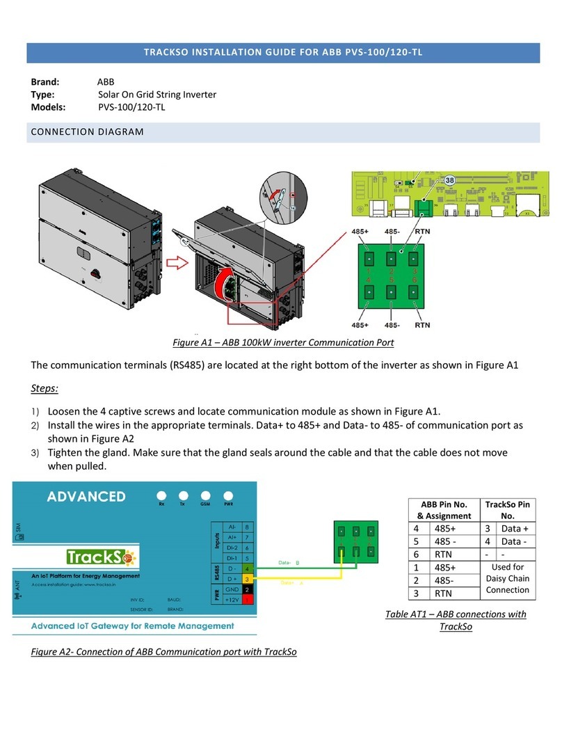
In order to connect the communication wiring to the inverter it is necessary to
replace the signal plug screw 20 with a 1/2” box connector (thread 14 NPSM) that
matches the wiring method chosen (e.g., conduit, exible conduit, etc.).
• Each cable connected to the communication
and control signals must pass through the
signal conduit 20 and signal wiring duct 17.
• RJ45 connectors a12 - RJ45 connectors
(A) and (B) available for the RS-485
communication are equivalent to each other and can be used interchangeably for input or output of the line to create a daisy chain connection
of the inverters.
• RS-485 connections a14 - If terminal blocks are used, signals RTN, +T/R and –T/R have to be cabled. Use a cable designed for use with
RS-485 communications such as Belden 3106A, which is a data cable wire with one twisted pair, one ground conductor, and a shield with
drain wire (equivalent). Locate mating connectors (provided in hardware bag) for the terminal block. Connect the three RS-485 leads (-RTN,
+T/R, -T/R) to the mating connector corresponding points. Attach the mating connector to line up with correct signals on either upper or lower
row of the terminal block.
• Daisy chain connection - Recommended length of total communication cable line for all inverters in the system is 1,000 meters (1094 yards)
or less. Depending on type of computer used, cable line
adaptor can be RS-485_RS232 or RS-485_USB.
• Termination switch A10 - On last inverter in a daisy
chain, or on a single inverter, activate termination
resistance of communication line by moving switch down
into ON position. All other inverters in daisy chain will
have the switch up in OFF position.
• Addressing each inverter - Default setting for RS-485
address is 2 and termination switch in OFF position.
When multiple inverters are connected in a daisy chain, it is
necessary to assign a different RS-485 address to each unit.
• The address can be changed before or after
commissioning using the display menu, see section 15.
Refer to the technical manual online for connections of signal
wiring a15.
The ±WT (WIND) terminals are not isolated and can
have hazardous voltages present. These terminals
must not be utilized for any purpose (for use with wind
models only).
RS485 CARD
J24
RS485(B)
17
1
18
J15
1
J16
2
J6
1
RS485
T/R
T/R
RTN
LNK
J14
BT1
CR2032
WIND
REM
WT
WT
R
R
RS485(A)
J13
ALARM
N.C.
N.O.
C
TERM.120
ON
OFF
S3
17
MEMORY CARD
J4
18
K4
J23
S1
1
S2
2
N
1
L
2
MOV3
3
MOV4
J25
RED
GFI
GFI
BLACK
W4
W3
WHITE
GND_MODE
W2
GRID
MOV2
J10
3
+IN
4
J20 F1
J5
1
5
2
9
6
14
11
J9
DC IN
-IN
1
-IN
2
J19
J7
1
MOV1
+IN
J17 J18
J8
1
20
RS485 CARD
J24
RS485(B)
17
1
18
J15
1
J16
2
J6
1
RS485
T/R
T/R
RTN
LNK
J14
BT1
CR2032
WIND
REM
WT
WT
R
R
RS485(A)
J13
ALARM
N.C.
N.O.
C
TERM.120
ON
OFF
S3
17
MEMORY CARD
J4
18
K4
J23
S1
1
S2
2
N
1
L
2
MOV3
3
MOV4
J25
RED
GFI
GFI
BLACK
W4
W3
WHITE
GND_MODE
W2
GRID
MOV2
J10
3
+IN
4
J20 F1
J5
1
5
2
9
6
14
11
J9
DC IN
-IN
1
-IN
2
J19
J7
1
MOV1
+IN
J17 J18
J8
1
4 5 6 1 2 3
FUSE
1720
a15 a14
a15 a14
-S Switchbox VersionNo Switchbox Version
In order to congure the ADDRESS settings (section 13) prior to grid connection, the inverter display only needs DC power to use the menus.
DO NOT connect the AC power (grid side) at this time! With only the array connected, set the inverter’s DC disconnect switch to ON.
GREEN POWER LED will ash and YELLOW ALARM LED will be steady. The message “Missing Grid” will display in area b10.
Press ESC to open the menus. Use the DOWN key to scroll to SETTINGS, and press ENTER. The SETTINGS menu requires an access password.
Upon selecting SETTINGS the password screen will open; the default password is 0000.
Pressing ENTER four times loads four zeroes on the display and opens the submenu.
• Area b10 has two visible text lines and the UP and DOWN keys are used to scroll through the menu items.
• Arrow > on the left side of the display highlights the current selection.
• Press UP or DOWN keys to move the arrow to the desired selection and press ENTER to open the associated submenu.
• To return to the preceding menu, press the ESC key.
Address: the RS-485 address may need to be changed or assigned.
• Default address is set at 2 for a single inverter.
• Scroll to Address and press ENTER to open the submenu.
• Address values are assigned manually using any value in the range 2 to 63.
• Press UP and DOWN keys to scroll through numbers and press ENTER to select, ESC to cancel.
• Turn DC disconnect switch 07 to OFF in order to save the changes.
The procedure for start up is as follows:
• Turn DC disconnect switch 07 to ON position.
• If there are two separate external disconnect switches (one for DC and the other for AC),
rst close the AC disconnect switch and then the DC disconnect switch. There is no order of priority for opening the disconnect switches.
• When the inverter has power, the rst check performed relates to input voltage:
If DC input voltage is lower than Vstart voltage (voltage required to begin the inverter’s grid connection) icon b14 remains off and the
“Waiting sun” message is displayed in area b10.
If DC input voltage is higher than Vstart voltage icon b14 is displayed and inverter goes to next stage . Voltage levels and input current
are displayed in the b15 and b16 elds.
• The inverter performs a control of grid parameters. Icon b22 represents grid distribution and can display the following states:
not present indicates AC voltage is absent, ashing indicates AC voltage is present but outside the parameters of the country of installation,
steady ON - indicates AC voltage is present and within the parameters of the country of installation; this status starts grid connection sequence.
• If the input voltage and the grid voltage are within the inverter operating intervals, connection to the grid will begin.
• Icon b21 represents an electrical plug that is connected when the inverter is connected to the grid and a disconnected when not connected.
When the connection sequence is complete, the inverter indicates its correct operation by making a sound and by the green LED coming on steady
on the LED panel. If the inverter signals any errors/warnings the messages and their codes will be indicated on the display.
Refer to full technical manual on the website for Error and Warning Codes.
POWER
LED
GREEN - On if the inverter is working correctly.
Flashes when checking the grid or if there is insufcient sunlight.
ALARM
LED
YELLOW - The inverter has detected an anomaly.
Anomaly is shown on the display area b10.
GFI LED RED - Ground fault on the DC side of the PV array.
Error is shown on the display area b10.
ESC Used to access the main menu, go back to the previous menu, or
go back to the previous digit to be edited.
UP Used to scroll up the menu options or shift the numerical scale.
DOWN Used to scroll down the menu options or shift the numerical scale.
ENTER
Used to conrm a selection, access the submenu for the selected
option (indicated by arrow > symbol), or move to the next digit to
be edited.
Operating parameters of the equipment are displayed on the LCD 01; LEDs 02 indicate
operating state of inverter. Keypad 03 is used to review data on the cyclical display b10,
and access data logged internally. LEDs 02 (warning lights) and KEYPAD 03 can be
used to carry out complex actions that are described more fully in the manual. Description
of symbols and display elds on the LCD 01 are found at right and illustrated below:
DC
AC
b1
b2
b3
b4 b6
b7 b9 b10
b17
b16
b14
b13
b12
b11 b15 b18
b20 b22
b21
b19
b23
b8
b5
b1 RS-485 data transmission b13 Daily energy produced
b2 RS-485 line present b14 PV voltage > Vstart
b3 Radio line present b15 DC voltage
b4 Bluetooth line present (*) b16 DC current
b5 WiFi line present (*) b17 DC/DC circuit part
b6 Warning b18 DC/AC circuit part
b7 Temperature derating b19 AC voltage
b8 Instantaneous power b20 AC current
b9 MPP scan running b21 Connection to the grid
b10 Graphic display b22 Grid status
b11 Power graph b23 Cyclic view on/off
b12 Total energy (*) NOT available
>Address
Display settings
Initializing . . .
Please wait
TECHNICAL DATA VALUES UNO-2.0-I-OUTD-US UNO-2.5-I-OUTD-US
Nominal Output Power W 2000 2500
Maximum Output Power W 2200** 2750**
Rated Grid AC Voltage V 208 240 277 208 240 277
Input Side (DC)
Number of Independent MPPT Channels 1 1
Maximum Usable Power for Each Channel W 2300 2900
Absolute Maximum Voltage V 520 520
Start- Up Voltage (Vstart) V200 (adj. 120-350 ) 200 (adj. 120-350 )
Full Power MPPT Voltage Range V170-470 200-470
Operating MPPT Voltage Range V 0.7xVstart-520 0.7xVstart-520
Maximum Usable Current A12.5 12.8
Maximum Short Circuit Current Limit A15 15
#of Wire Landing Terminals Per Channel 2 Pairs 2 Pairs
Array Wiring Termination Terminal block, Pressure Clamp, 12AWG-6AWG Terminal block, Pressure Clamp, 12AWG-6AWG
Output Side (AC)
Grid Connection Type 1Ø/2W Split-Ø/3W 1Ø/2W 1Ø/2W Split-Ø/3W 1Ø/2W
Adjustable Voltage Range (Vmin-Vmax) V183-228 211-264 244-304 183-228 211-264 244-304
Grid Frequency Hz 60 60
Adjustable Grid Frequency Range Hz 57-63 57-63
Maximum Current A10 12
Power Factor > 0.990 > 0.990
Total Harmonic Distortion At Rated Power % < 2 < 2
Grid Wiring Termination Type Terminal Block, Pressure Clamp, 12AWG-6AWG Terminal Block, Pressure Clamp, 12AWG-6AWG
Protection Devices
Input
Reverse Polarity Protection Yes Yes
Over-Voltage Protection Type Varistor, 2 Varistor, 2
PV Array Ground Fault Detection Meets UL1741/NEC 690.5 requirements
PV Array Isolation Control GFDI (for use with either Positive or Negative Grounded Arrays)
Output
Anti-Islanding Protection Meets UL 1741/IEE1547 requirements Meets UL 1741/IEE1547 requirements
Over-Voltage Protection Type Varistor, 2 (L1- L2/ L1- G) Varistor, 2 (L1- L2/ L1- G)
Maximum AC OCPD Rating A15 15
Efciency
Maximum Efciency % 96.6 96.6
CEC Efciency % 95.5 95.5 95.5 95.5 96 96
Operating Performance
Stand-by Consumption WRMS < 8 < 8
Night Time Consumption WRMS < 0.6 < 0.6
Communication
User-Interface 5.5” x 1.25” Graphic Display
Remote Monitoring AURORA-UNIVERSAL (opt.)
Wired Local Monitoring PVI-USB-RS-485_232 (opt.), PVI-DESKTOP (opt.)
Wireless Local Monitoring PVI-DESKTOP (opt.) with PVI-RADIOMODULE (opt.)
Environmental
Ambient Air Operating Temperature Range °F (°C) -13 to +140 (-25 to +60) with automatic derating
above 122 (50)
-13 to +140 (-25 to +60) with automatic derating
above 113 (45)
Ambient Air Storage Temperature Range °F (°C) -40 to +176 (-40 to +80) -40 to +176 (-40 to +80)
Relative Humidity %0-100 condensing 0-100 condensing
Acoustic Noise Emission Level db (A) 1m < 50 < 50
Maximum Altitude for Full Power Operation ft(m) 6560 (2000) 6560 (2000)
Mechanical Specications
Enclosure rating NEMA 4X
Cooling Natural Convection
Dimensions (H x W x D) in (mm) 30.3 x 14.4 x 6.3 (769 x 367 x 161) with switch
Weight lb (kg) 42.5 (19.3) with switch
Mounting System Wall bracket
Conduit Connections*** Bottom: (2) 3/4” EKO , (3) 1/2” EKO / Left and Right Side: (1) 3/4” EKO / Back: (4) 3/4” EKO
DC Switch Rating 16 A / 600 VDC
Safety
Isolation Level High-Frequency Transformer
Safety and EMC Standard UL1741(2010), IEE1547, IEE1547.1, CSA C22.2 N. 107.1-01, FCC Part 15 Class B , UL1998 UL1699B
Safety Approval cCSAus
Warranty
Standard Warranty years 10 10
Extended Warranty years 15 & 20 15 & 20
Available Models
Standard UNO-2.0-I-OUTD-US UNO-2.5-I-OUTD-US
With DC Switch and Wiring Box UNO-2.0-I-OUTD-S-US UNO-2.5-I-OUTD-S-US
*All data is subject to change without notice
** Capability enabled at nominal AC voltage and with sufcient DC power available
*** When equipped with optional DC Switch and Wiring Box
Grid settings Top
switch
Bottom
switch
Display
Language
UL 1741 @208V Single Phase 0 2 English
UL 1741 @240V Split Phase 0 3 English
UL 1741 @277V Single Phase 04English
Contact us
www.abb.com/solarinverters
NEGATIVE POSITIVE
Conrm the DC voltage in the switchbox has correct polarity and
is within the operational range (section 16) prior to terminating.
