manuals.online logo
Brands
  1. Home
  2. •
  3. Brands
  4. •
  5. ABB
  6. •
  7. Safety Equipment
  8. •
  9. ABB Nexus RF User manual

ABB Nexus RF User manual

—
INSTALLATION MANUAL
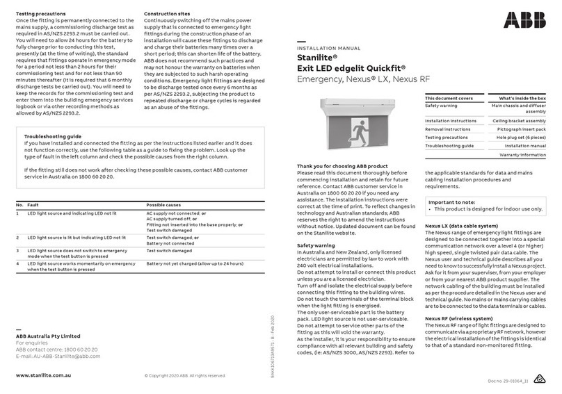
Stanilite®
Platinum Spitfire® LED recessed
Nexus® RF
Doc no. 29-WSIS001_A
This document covers What’s inside the box
Safety warning Lamp head assembly
Installation instructions Battery and control pack
Removal instructions Accessory kit
Testing precautions Installation manual
Troubleshooting guide Warranty information
Troubleshooting guide
If you have installed and connected the fitting as per the instructions listed earlier and it does
not function correctly, use the following table as a guide to fixing the problem. Look up the
type of fault in the left column and check the possible causes from the right column.
If the fitting still does not work after checking these possible causes, contact ABB customer
service in Australia on 1800 60 20 20.
—
ABB Australia Pty Limited
For enquiries
ABB contact centre: 1800 60 20 20
E-mail: AU-ABB-Stanilite@abb.com
www.stanilite.com.au © Copyright 2019 ABB. All rights reserved.
9AKK1074920280 - A - May 2019
Thank you for choosing ABB product
Please read this document thoroughly before
commencing installation and retain for future
reference. Contact ABB customer service in
Australia on 1800 60 20 20 if you need any
assistance. The installation instructions were
correct at the time of print. To reflect changes in
technology and Australian standards; ABB
reserves the right to amend the instructions
without notice. Updated document can be found
on the Stanilite website.
Safety warning
In Australia and New Zealand, only licensed
electricians are permitted by law to work with
240 volt electrical installations.
Do not attempt to install or connect this product
unless you are a licensed electrician.
Turn off and isolate the electrical supply before
connecting this fitting to the building wires.
Do not touch the terminals of the terminal block
when the light fitting is energised.
The only user-serviceable parts are the lamp head
assembly and battery pack. LED light source is
not user-serviceable.
Do not attempt to service other parts of the
No. Fault Possible causes
LED light source and indicating LED not lit AC supply not connected; or
AC supply turned off; or
Test switch damaged
LED light source is lit but indicating LED not lit Test switch damaged; or
Battery not connected or faulty
LED light source does not switch to emergency
mode when the test button is pressed
Test switch damaged; or
Battery not connected or faulty
LED light source works momentarily on emergency
when the test button is pressed

fitting as this will void the warranty.
As the installer, it is your responsibility to ensure
compliance with all relevant building and safety

the applicable standards for data and mains
cabling installation procedures and
requirements.
As per AS 60598.2.2:2016 the recessed luminaire
classification is CA90.
Note: Not suitable for use with loose-fill
insulation.
The control pack and battery pack must be
installed above the insulation. No fire rated box is
required for the product.
Important to note:
• This product is designed for indoor use only.
Nexus RF (wireless system)
The Nexus RF range of light fittings are designed to
communicate via a proprietary RF network, however
the electrical installation of the fittings is identical
to that of a standard non-monitored fitting.
Installation instructions
1. Note: The circuit supplying mains power to the fitting must not be energised until installation of
the fitting is completed.
2. Mark and cutout a hole in the ceiling to suit either small or large Spitfire head. The cut-out size for
the standard lamp head is 50mm. The cut-out size for a small 85mm adaptor plate is 70mm and for
the large 141mm adaptor plate is 130mm. Note: The adaptor plates are mainly used for existing
Spitfire replacement or where access is limited.
3. 
4. Connect battery pack and lamp head to the control pack. The battery pack can be attached to the
control pack using cable tie supplied. Secure the battery pack and lamp head wires to the control
pack using cable tie.
5. Connect data cable to the control pack.
6. Feed the battery and control pack assembly through the ceiling cut-out and secure them to a
suitable location within the ceiling space. If access to the ceiling cavity is not available, connect the
mains power cord before recessing the battery and control pack in the ceiling cut-out. Secure the
battey and control pack to a suitable location within the ceiling space.
7. Refer to data connections section.
8. Connect flex and plug to the supply socket.
9. Check operation of the fitting to ensure that the installation was successful. Once powered up, as
a non-maintained fitting the present lamp stays off. Allow a few minutes to give the battery a small
charge, then press the test button located at the Spitfire lamp head. Hold the test button in for a
few seconds and observe the operation of the lamp switching from mains to the emergency mode.
If the lamp on emergency mode works momentarily, that’s okay. Try again in a few more minutes in
case battery is completely discharged, it may take a little time to charge up enough to operate
even momentarily. After this time, press the test button again and if the lamp does not work at all,
check the supply, the connections and follow the instruction given in the troubleshooting guide at
the end of this document. Operation modes of the LED status should be as follows.
10. Once manually checked, it is ready for the commissioning into the Nexus network. Keep the


information as all of this will be required for entry into the database during commissioning. Refer
to the Nexus user and technical guide for full details. As the installer, it is your responsibility to
conduct the initial discharge testing of the installed fitting. Refer to AS/NZS 2293.
Important: 24 hours is required to allow the fitting battery to reach full capacity, ie: prior to a
discarge test. As the installer, it is your responsibility to conduct the initial discharge testing of the
installed fitting. Refer to AS/NZS 2293.
Removal instructions
1. Before removing the installed fitting, de-
energise and lock off the supply circuit.
Fitting type Indicator LED state - on initial powering - no fitting faults
Nexus RF 
Data connections - Nexus RF product range
Nexus RF fitting
• Connect the antenna to the control pack.
• Collect the MAC address, by removing the
peel off sticker section and locating it on
your floor plan or spreadsheet.
• Consult the Nexus user and technical guide
for further detail, including product
commissioning.
Testing precautions
Once the fitting is permanently connected to the
mains supply, a commissioning discharge test as
required in AS/NZS 2293.2 must be carried out.
You will need to allow 24 hours for the battery to
fully charge prior to conducting this test,

requires that fittings operate in emergency mode
for a period not less than 2 hours for their
commissioning test and for not less than 90
minutes thereafter (it is required that 6 monthly

keep the records for the commissioning test and
enter them into the building emergency services
logbook or via other recording methods as
allowed by AS/NZS 2293.2.
Construction sites
Continuously switching off the mains power
supply that is connected to emergency light
fittings during the construction phase of an
installation will cause these fittings to discharge
and charge their batteries many times over a
short period; this can shorten life of the battery.
ABB does not recommend such practices and
may not honour the warranty on batteries when
they are subjected to such harsh operating
conditions. Emergency light fittings are designed
to be discharge tested once every 6 months as
per AS/NZS 2293.2, subjecting the product to
repeated discharge or charge cycles is regarded
as an abuse of the fittings.
2. Unplug the power cord from the mains
socket.
3. Disconnect the battery and lamp head plug.
Power cable Main control unit
Figure 1: Product installed in ceiling
Figure 2: Connection and
cable tie location
Other ABB Safety Equipment manuals

ABB jokab safety Smile 11EA Tina User manual

ABB

ABB jokab safety Smile 11EA Tina User manual

ABB Stanilite Platinum exit LED Quickfit User manual

ABB

ABB Stanilite Platinum exit LED Quickfit User manual

ABB HD5-S User manual

ABB

ABB HD5-S User manual

ABB PrimEvo XT100E Manual

ABB

ABB PrimEvo XT100E Manual

ABB RD344 User manual

ABB

ABB RD344 User manual

ABB XT230H/DALI Manual

ABB

ABB XT230H/DALI Manual

ABB SafeMove2 Instructions for use

ABB

ABB SafeMove2 Instructions for use

ABB XT230RS/DALI Manual

ABB

ABB XT230RS/DALI Manual

ABB JSM D23C User manual

ABB

ABB JSM D23C User manual

ABB Stanilite Spitfire Standard User manual

ABB

ABB Stanilite Spitfire Standard User manual

ABB Tina 1A User manual

ABB

ABB Tina 1A User manual

ABB Thomas & Betts RH Series User manual

ABB

ABB Thomas & Betts RH Series User manual

ABB INCA 1EC Tina User manual

ABB

ABB INCA 1EC Tina User manual

ABB Jokab Safety Safeball JSTD1 User manual

ABB

ABB Jokab Safety Safeball JSTD1 User manual

ABB Stanilite Exit LED edgelit Quickfit User manual

ABB

ABB Stanilite Exit LED edgelit Quickfit User manual

ABB Stanilite Platinum Spitfire LED weatherproof User manual

ABB

ABB Stanilite Platinum Spitfire LED weatherproof User manual

ABB Welcome User manual

ABB

ABB Welcome User manual

Popular Safety Equipment manuals by other brands

Eaton BG3 Technical manual

Eaton

Eaton BG3 Technical manual

Pepperl+Fuchs F2-SP-IC Series instruction manual

Pepperl+Fuchs

Pepperl+Fuchs F2-SP-IC Series instruction manual

Kemper FK-5 operating instructions

Kemper

Kemper FK-5 operating instructions

SSP HOLDX RS1 operating manual

SSP

SSP HOLDX RS1 operating manual

DITEC AST installation manual

DITEC

DITEC AST installation manual

USP Bravo BRV2A-1-1-CLSL-MP1 operating instructions

USP

USP Bravo BRV2A-1-1-CLSL-MP1 operating instructions

HALDER 22352.2008 quick start guide

HALDER

HALDER 22352.2008 quick start guide

HOGERT HT5K178 user manual

HOGERT

HOGERT HT5K178 user manual

Werner A519000 instruction manual

Werner

Werner A519000 instruction manual

SICK UE4155 PROFIsafe operating instructions

SICK

SICK UE4155 PROFIsafe operating instructions

Bosch D129 installation instructions

Bosch

Bosch D129 installation instructions

KAPPLER Zytron User information

KAPPLER

KAPPLER Zytron User information

asalvo 11374 instructions

asalvo

asalvo 11374 instructions

Sperian Fendall Pure Flow 1000 manual

Sperian

Sperian Fendall Pure Flow 1000 manual

Jippie's 83613 quick start guide

Jippie's

Jippie's 83613 quick start guide

Viking YouSafe Junior user manual

Viking

Viking YouSafe Junior user manual

pizzato CS MP310 Series manual

pizzato

pizzato CS MP310 Series manual

Sordin Supreme Pro-X quick guide

Sordin

Sordin Supreme Pro-X quick guide

manuals.online logo
manuals.online logoBrands
  • About & Mission
  • Contact us
  • Privacy Policy
  • Terms and Conditions

Copyright 2025 Manuals.Online. All Rights Reserved.