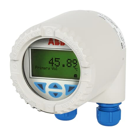
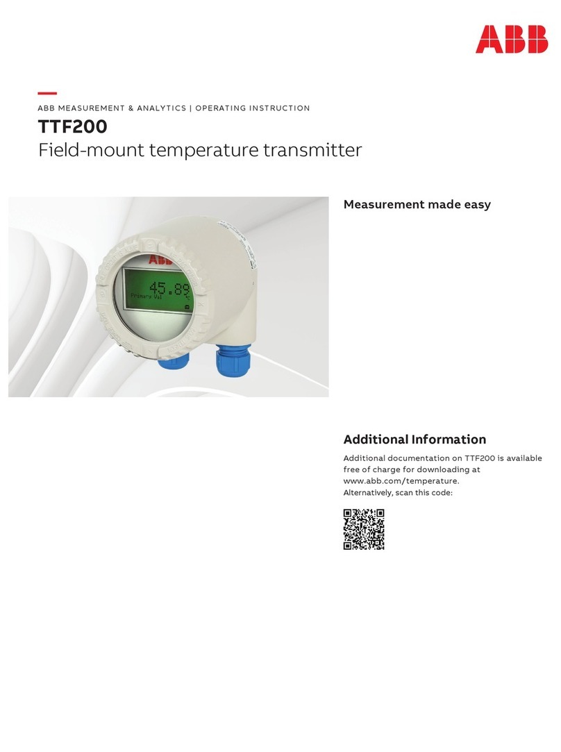
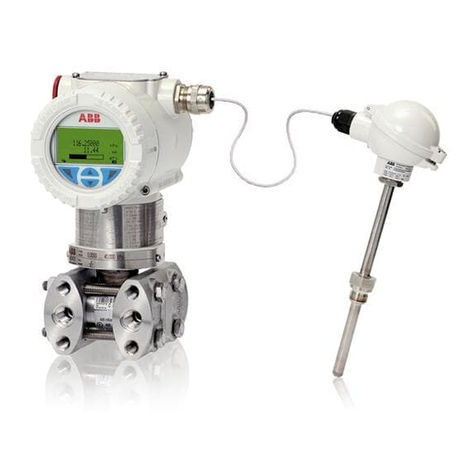
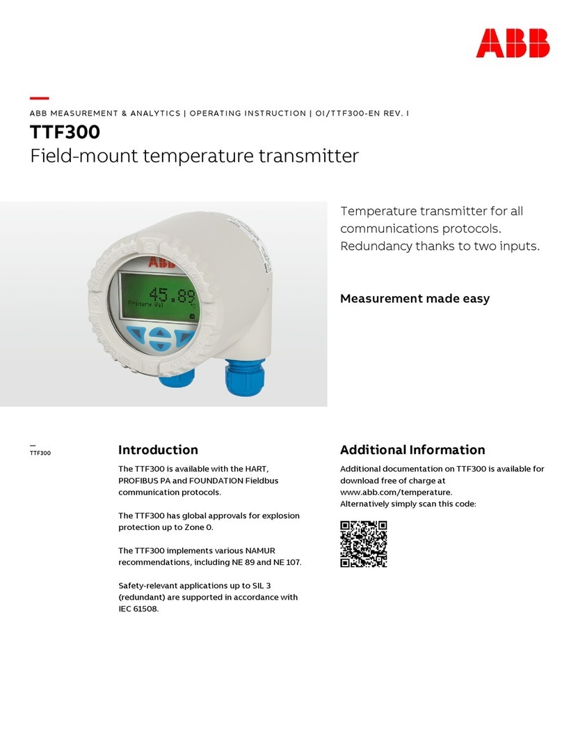
ABB TTF350 User manual

Operating Instructions
OI/TTF350-EN
Field mounted Temperature Transmitters
TTF350

Blinder Text
2 TTF350 OI/TTF350-EN
Field mounted Temperature Transmitters
TTF350
Operating Instructions
OI/TTF350-EN
08.2007
Manufacturer:
ABB Automation Products GmbH
Borsigstraße 2
63755 Alzenau
Germany
Tel.: +49 551 905-534
Fax: +49 551 905-555
[email protected]b.com
© Copyright 2007 by ABB Automation Products GmbH
Subject to change without notice
This document is protected by copyright. It assists the user with the safe and efficient operation of the
device. The contents may not be copied or reproduced in whole or in excerpts without prior approval of
the copyright holder.
Contents

Contents
OI/TTF350-EN TTF350 3
1Safety....................................................................................................................................................................6
1.1 General Safety Information ............................................................................................................................6
1.2 Intended use...................................................................................................................................................6
1.3 Technical limits...............................................................................................................................................6
1.4 Warranty provision .........................................................................................................................................7
1.5 Labels and symbols........................................................................................................................................7
1.5.1 Symbols and warnings ............................................................................................................................7
1.5.2 Name plate..............................................................................................................................................8
1.6 Operator liability .............................................................................................................................................8
1.7 Personnel qualification ...................................................................................................................................8
1.8 Returning devices...........................................................................................................................................9
1.9 Disposal..........................................................................................................................................................9
1.9.1 Information on WEEE directive 2002/96/EC (Waste Electrical and Electronic Equipment) ...................9
1.10 Transport safety information ..........................................................................................................................9
1.11 Electrical installation safety information .......................................................................................................10
1.12 Operating safety information ........................................................................................................................10
2Use in areas requiring ignition protection ......................................................................................................11
2.1 Approvals .....................................................................................................................................................11
2.2 Ground..........................................................................................................................................................11
2.3 Interconnection.............................................................................................................................................11
2.4 Configuration ................................................................................................................................................11
2.5 Explosion-protection relevant information ....................................................................................................11
3Design and function ..........................................................................................................................................12
4Installation..........................................................................................................................................................13
4.1 Installation options........................................................................................................................................13
4.1.1 Wall installation .....................................................................................................................................13
4.1.2 Pipe installation .....................................................................................................................................14
4.2 Installing and aligning the optional LCD display with control buttons ..........................................................15
5Electrical connection ........................................................................................................................................16
5.1 Conductor material .......................................................................................................................................16
5.2 Connection for power supply cable ..............................................................................................................17
5.3 Connection for measuring element ..............................................................................................................18
5.4 Cable glands ................................................................................................................................................19
5.4.1 TTF350 without cable gland..................................................................................................................19
5.4.2 TTF350 EEx d models without cable gland ..........................................................................................19
5.5 Terminal connection diagrams .....................................................................................................................20
5.5.1 Standard application .............................................................................................................................22
5.5.2 Installation in ignition protection areas..................................................................................................25
6Startup Operation ..............................................................................................................................................33

Contents
4 TTF350 OI/TTF350-EN
7Configuration .....................................................................................................................................................33
7.1 Configuration options / Communication .......................................................................................................33
7.2 Configuration via FDT/DTM technology .......................................................................................................34
7.3 Configuration via EDD technology ...............................................................................................................34
7.4 Configuration with the handheld terminal.....................................................................................................34
7.5 Configuration via the LCD display / configuration software with the control buttons ...................................34
7.5.1 Configuration via the control buttons of the LCD display......................................................................35
7.5.2 Menu navigation....................................................................................................................................36
7.5.3 Example of configuration changes........................................................................................................38
7.5.4 Activating software write protection ......................................................................................................40
7.5.5 Deactivating software write protection ..................................................................................................40
7.5.6 LCD display / configuration software menu structure ...........................................................................41
7.6 Hardware write protection via DIP switch.....................................................................................................44
82-sensor input functionality / Dual sensor mode...........................................................................................45
8.1 2-HART measurement signals .....................................................................................................................45
8.2 Redundancy / sensor backup.......................................................................................................................45
8.3 Sensor drift detection ...................................................................................................................................47
8.4 Sensor error compensation (TTF350 DTM Adjust function / in HMI LCD display Calibrate function).........49
8.5 D/A analog output compensation (4 and 20 mA trim) ..................................................................................49
8.6 HART variable assignment...........................................................................................................................50
8.7 Communication / HART tag / Device address..............................................................................................50
8.8 Description of parameters ............................................................................................................................51
8.8.1 Factory settings.....................................................................................................................................58
9Error messages .................................................................................................................................................59
10 Additional TTF350 DTM diagnostic information ............................................................................................62
10.1 Long-term monitoring ...................................................................................................................................62
10.2 Operating hour statistics...............................................................................................................................62
11 Maintenance / Repair.........................................................................................................................................63
11.1 General information......................................................................................................................................63
11.2 Cleaning .......................................................................................................................................................63
12 Explosion-protection relevant information.....................................................................................................64
12.1 TTF350-E1 .. H: (intrinsic safety) .................................................................................................................64
12.2 TTF350 -E2 .. H: (non-incendive).................................................................................................................64
13 Approvals ...........................................................................................................................................................65
13.1 TTF350.........................................................................................................................................................65
14 Technical data....................................................................................................................................................66
14.1 Input..............................................................................................................................................................66
14.1.1 Resistance.............................................................................................................................................66
14.1.2 Thermocouples/Voltages ......................................................................................................................66
14.2 Output...........................................................................................................................................................66

Contents
OI/TTF350-EN TTF350 5
14.3 Power supply (polarity safe) .........................................................................................................................67
15 General information ..........................................................................................................................................67
15.1 Ambient conditions .......................................................................................................................................67
15.2 Electromagnetic compatibility.......................................................................................................................67
15.3 Interference immunity...................................................................................................................................67
16 LCD-display........................................................................................................................................................68
16.1 Features of the LCD display.........................................................................................................................68
16.1.1 Technical data of LCD display ..............................................................................................................68
16.2 Configuration function of LCD display..........................................................................................................68
16.3 LCD display HMI ignition-proof type B (intrinsically safe) ............................................................................68
17 Appendix ............................................................................................................................................................69
17.1 Permits and certifications .............................................................................................................................69
17.2 Additional documents ...................................................................................................................................69
18 Index ...................................................................................................................................................................71

Safety
6 TTF350 OI/TTF350-EN
1 Safety
1.1 General Safety Information
The “Safety” chapter provides an overview of the safety aspects to be observed for the
operation of the device.
The device is built based on state-of-the-art technology and is operationally safe. It was tested
and left the factory in a proper state. The requirements in the manual as well as the
documentation and certificates must be observed and followed in order to maintain this state for
the period of operation.
The general safety requirements must be complied with completely during operation of the
device. In addition to the general information, the individual chapters of the manual contain
descriptions about processes or procedural instructions with specific safety information.
Only the observance of all safety information enables the optimal protection of personnel as well
as the environment from hazards and the safe and trouble-free operation of the device.
1.2 Intended use
This device is intended for the following uses:
• To measure the temperature of fluid, pulpy or pasty substances and gases or
resistance/voltage values.
The following items are included in the intended use:
• Read and follow the instructions in this manual.
• Observe the technical ratings (refer to the section “Technical data” or data sheet).
Repairs, alterations and enhancements or the installation of replacement parts is only
permissible as far as described in the manual. Further actions must be verified with ABB
Automation Products GmbH. Excluded from this are repairs performed by ABB-authorized
specialist shops.
1.3 Technical limits
The device is designed for use exclusively within the stated values on the name plate and in the
technical specifications (see "Technical Specifications” chapter and/or data sheet). These must
be complied with accordingly, e.g.:
• The maximum operating temperature may not be exceeded.
• The permitted operating temperature may not be exceeded.
• The housing protection system must be observed.

Safety
OI/TTF350-EN TTF350 7
1.4 Warranty provision
A use contrary to the device’s stipulated use, disregarding of this manual, the use of under-
qualified personnel as well as unauthorized alterations excludes the manufacturer of liability
from any resulting damages. The manufacturer’s warranty expires.
1.5 Labels and symbols
1.5.1 Symbols and warnings
Danger – <Serious damage to health / risk to life>
One of these symbols in conjunction with the “Danger“ warning indicates an imminent danger.
If it is not avoided, death or serious injury will result.
Warning – <Bodily injury>
The symbol in conjunction with the “Warning“ message indicates a possibly dangerous
situation. If it is not avoided, death or serious injury could result.
Caution – <Slight injuries>
The symbol in conjunction with the “Caution“ message indicates a possibly dangerous
situation. If it is not avoided, slight or minor injury can result. May also be used for property
damage warnings.
Notice – <Property damage>!
The symbol indicates a possibly damaging situation. If it is not avoided, the product or
something in its area can be damaged.
Important
The symbol indicates operator tips or especially useful information. This is not a message for a
dangerous or damaging situation.

Safety
8 TTF350 OI/TTF350-EN
1.5.2 Name plate
The model plate is located on the transmitter housing.
A00186
Automation Products GmbH
Alzenau Germany 2006
TTF350
U = +11... 42 V, I = 4 ... 20 mA, HART
Cfg. 2 x TC; Type K; 0°C ... 300°C
T = -40°C ... +85°C
Sa
a
O-Code: TTF350-Y0C4/OPT 8323455772
Ser.-No: 123456789012
3
2
1
4
5
6
7
12
13
11
10
9
8
HW-Rev: 1.05
SW-Rev: 01.00.00
IP6X, NEMA 4X
14
0102
15
Fig. 1
1 Manufacturer of transmitter
2 Order code with SAP no.
3 Serial number
4 Approved power supply, current
communications protocol
5 Configured parameters
6 Permissible ambient temperature
7 Hardware version
8 Software version
9 Level of protection
10 CE mark (EC conformity)
11 Refer to product documentation
12 Transmitter model
13 SIL mark
14 Year of manufacture
15 Country
Important
The temperature range on the model plate (6) refers only to the permissible ambient
temperature range for the transmitter and not to the measuring element used in the measuring
inset.
1.6 Operator liability
Before the use of corrosive and abrasive materials to be measured, the operator must clarify the
resistance of all parts that come into contact with the materials to be measured. ABB will gladly
support you with the selection, however, cannot accept any liability.
The operators must strictly observe the applicable national regulations in their countries with
regards to installation, function tests, repairs, and maintenance of electrical devices.
1.7 Personnel qualification
The installation, commissioning and maintenance of the device may only be carried out through
trained specialist personell authorized by the plant operator. The specialist personnel must have
read and understood the manual and comply with its instructions.

Safety
OI/TTF350-EN TTF350 9
1.8 Returning devices
Use the original packaging or a suitably secure packaging for returning the device for repair or
for recalibration. Include the properly filled out return form (see attachment) with the device.
According to EC guidelines for hazardous materials, the owner of hazardous waste is
responsible for its disposal or must observe the following regulations for its shipping:
All delivered devices to ABB Automation Products GmbH must be free from any hazardous
materials (acids, alkali, solvents, etc.).
1.9 Disposal
ABB Automation Products GmbH actively promotes environmental consciousness and has an
operational management system in accordance with DIN EN ISO 9001:2000, EN ISO
14001:2004 and OHSAS 18001. Our products and solutions should have minimum impact on
the environment and persons during manufacture, storage, transport, use and disposal.
This includes the environmentally friendly use of natural resources. Through its publications
ABB conducts an open dialog with the public.
This product/solution is manufactured from materials that can be reused by specialized
recycling companies.
1.9.1 Information on WEEE directive 2002/96/EC (Waste Electrical and Electronic Equipment)
This product/solution is not subject to the WEEE directive 2002/96/EC and relevant national
laws (e.g., ElektroG in Germany).
Dispose of the product/solution directly in a specialized recycling facility and do not use the
municipal garbage. Only privately used products may be disposed of in the municipal garbage
according to the WEEE directive 2002/96/EC. Proper disposal prevents negative effects on
people and the environment, and supports the reuse of valuable raw materials.
If it is not possible to dispose of old equipment properly, ABB Service can accept and dispose of
returns for a fee.
1.10 Transport safety information
Observe the following information:
• Do not expose the device to moisture during transport. Pack the device accordingly.
• Pack the device so that it is protected from vibration during transport, e.g. through air-
cushioned packaging.
Check the devices for possible damage that may have occurred from improper transport.
Damages in transit must be recorded on the transport documents. All claims for damages must
be claimed without delay against the shipper and before the installation.

Safety
10 TTF350 OI/TTF350-EN
1.11 Electrical installation safety information
The electrical connection may only be performed by authorized specialist personnel according
to the electrical plans.
Observe the electrical connection information in the manual, otherwise the electrical protection
can be affected.
The secure isolation of contact-dangerous electrical circuits is only guaranteed when the
connected devices fulfil the requirements of the DIN VDE 0106 T.101 (basic requirements for
secure isolation).
For secure isolation, run the supply lines separated from contact-dangerous electrical circuits or
additionally isolate them.
1.12 Operating safety information
Before switching on, ensure that the specified environmental conditions in the “Technical
Specifications” chapter and/or in the data sheet are complied with and that the power supply
voltage corresponds with the voltage of the transmitter.
When there is a chance that safe operation is no longer possible, put the device out of operation
and secure against unintended operation.

Use in areas requiring ignition protection
OI/TTF350-EN TTF350 11
2 Use in areas requiring ignition protection
Special regulations must be observed in explosion-protection zones for the auxiliary power
connection, signal inputs/outputs and ground connection. Information on ignition protection in
the separate chapters must be observed.
Caution! Potential damage to parts!
All parts must be installed in accordance with manufacturer information and relevant
standards and regulations.
Startup and operation must be performed in accordance with ATEX 137 or BetrSichV
(EN60079-14).
2.1 Approvals
The approvals for use of the TTF350 temperature transmitter in explosion-protection areas can
be found in the section "Approvals".
2.2 Ground
If for functional reasons, the intrinsically safe circuit has to be grounded by connection to the
equipotential bonding system, it may only be grounded at a single location.
2.3 Interconnection
If transmitters are operated in an intrinsically safe circuit, proof that the interconnection is
intrinsically safe must by provided in accordance with DIN VDE 0165/08.98 (EN 60 079-14/1997
and IEC 60 079-14/1996). In general, intrinsically safe circuits require proof of interconnection.
2.4 Configuration
TTF350 temperature transmitters can be installed in the explosion-protection area in
compliance with the proof of interconnection and directly in the explosion-protection area using
approved handheld HART terminals (e.g., HC275) as well as by coupling an ignition-proof
modem to the circuit outside the explosion-protection area.
2.5 Explosion-protection relevant information
For additional information, refer to the section “Explosion-protection relevant information”.

Design and function
12 TTF350 OI/TTF350-EN
3 Design and function
TTF350 digital transmitters are communication-ready field devices with microprocessor-
controlled electronics. For bidirectional communication, an FSK signal is superimposed on the
4 … 20 mA output signal via the HART protocol.
The graphic user interface (DTM) can be used to configure, poll and test transmitters on a PC-
specific basis. Handheld terminals also support communication.
The transmitter is equipped with an LCD display. The LCD display is used to visualize the
current process data. The four control buttons can be used to perform a local configuration.
For explosion-proof designs, the Ex design is described on a separate plate.
A00192
1
2
3
4
5
Fig. 2
1 Signal/power supply cable
2 Transmitter TTF350
3 Temperature sensor head
4 Processing pipe
5 Sensor connection cable

Installation
OI/TTF350-EN TTF350 13
4 Installation
4.1 Installation options
There are two ways to install transmitters:
• Wall installation
• Pipe installation
Important
The transmitter is available with optional type B LCD display / configuration software.
4.1.1 Wall installation
A00183
241 / 9.49241 / 9.49
175 / 6.89175 /6.89
175 / 6.89175 /6.89
241 / 9.49241 / 9.49
1
2
33
2
1
Fig. 3: Dimensions in mm/inches
1 Wall
3 Transmitter TTF350
2 Wall mount
1. Locate an installation site close to the temperature sensor head.
Warning - General hazards!
The transmitter can fall and be damaged if not firmly attached. There is also a risk that
persons can be injured.
Install the wall mount on a sufficiently stable wall only.
2. Screw the transmitter to the wall mount.
3. Attach the wall mount securely with 2 screws (∅10 mm).

Installation
14 TTF350 OI/TTF350-EN
4.1.2 Pipe installation
A00184
179 / 7.05
137/5.39
179 / 7.05
137/5.39
1
2
3
1
2
3
Fig. 4: Dimensions in mm/inches
1 Pipe (max. Ø 2 inches)
3 Transmitter TTF350
2 Pipe mount
1. Locate an installation site on a pipe close to the temperature sensor head.
Important
The pipe mount can be attached to a pipe with a maximum diameter of 2" (max. 60 mm).
2. Screw the transmitter to the pipe mount.
3 Attach the pipe mount securely to the pipe with 2 pipe clamps (∅10 mm).
Important
The wall and pipe installation set supports variable installation positions. A few examples of
the different options are shown here. The mounting screw allows infinitely adjustable
positioning (0° … 360°) of the housing.

Installation
OI/TTF350-EN TTF350 15
4.2 Installing and aligning the optional LCD display with control buttons
A00182
1
2
3
Ø 72,8 / 2.86
Ø 24,4 / 0.96
Ø 29,5 / 1.16
Fig. 5
1 Front view
2 Side view
3 Rear view of LCD display / plug positions
The LCD display is attached to the housing of the TTF350 transmitter.
1 Unscrew the housing cover for the transmitter.
2. Carefully remove the LCD display from the inset for the transmitter. The LCD display is held
firmly in place. You might have to use the tip of a screwdriver to pry loose the LCD display.
Avoid mechanical damage.
3. No tools are required to insert the LCD display, which can be mounted in 4 positions at 90
degree intervals to ensure the display is mounted properly and readable.
4. Screw on the housing cover for the transmitter.

Electrical connection
16 TTF350 OI/TTF350-EN
5 Electrical connection
Warning – Electrical voltage risk!
Observe the corresponding instructions for the electrical installation. Only connect in dead-
voltage state!
Since the transmitter has no switch-off elements, overvoltage protection devices, lightning
protection or voltage separation capacity must be provided on the plant side.
Energy supply and signal are routed in the same line and are to be implemented as SELV or
PELV circuit according to norm (standard version). In the ignition-proof version, the guidelines
according to the ignition-proof norms are to be adhered to.
It must be checked whether the existing power supply corresponds with the specifications on
the name plate and the technical specifications (see “Technical Specifications" chapter and/or
data sheet).
Important
The electrical connection is carried out with the transmitter in the installed state.
The signal cable wires must be provided with wire end sleeves.
The cross-head screws of the connection terminals are tightened with a size 1 screwdriver
(3.5 mm or 4 mm).
5.1 Conductor material
• Standard conductor material must be used for the power supply cable.
• The maximum peripheral wire cross section is 2.5 mm2.
Caution! Potential damage to parts!
A rigid conductor material can result in wire breaks.
The connecting cable must be flexible.
Line length
From the lower edge of the housing (no cable gland) to the hole in the clamping area, an
additional 100 mm of line is needed. An overall line length (without cable gland) of approx. 200
mm is required (approx. 100 mm bared).

Electrical connection
OI/TTF350-EN TTF350 17
5.2 Connection for power supply cable
Caution - Potential damage to parts!
Connecting the power supply cable with power switched on may result in a short circuit and
potential damage to the transmitter.
The power must be switched off to connect the power supply cable.
6
5
4
3
2
1
PA
PA
+
-
1
2
3
4
5
6
7
7
8
9
A00187
Fig. 6 Sensor and supply voltage terminal box of the TTF350 field device
1 … 6 Sensor connection
7 … 9 Signal/power supply connection
11 ... 42 VDC / 4 … 20 mA
11 … 30 VDC / 4 … 20 mA (Ex)
7 Shield
8 Minus
9 Plus
1. Route the power supply cable through the cable gland into the housing of the transmitter.
Then tighten the cable gland.
2. Strip the wires and attach wire end sleeves.
3. Release the clamping screws for the (+) and (-) terminals with the proper screwdriver. Make
sure that the screws do not fall out.
4. Connect the (+) wire to the (+) terminal on the transmitter.
5. Connect the (-) wire to the (-) terminal on the transmitter.
The connection of the line shield is optional.

Electrical connection
18 TTF350 OI/TTF350-EN
5.3 Connection for measuring element
Important
The model of the sensor connecting cable must correspond to the sensor model and
configuration of the transmitter.
When connecting the transmitter and measuring inset (sensor) make sure for thermocouple
sensors that the material of the sensor connecting cable corresponds to the thermocouple
model.
1. Look for the connection type for the selected measuring element in the connection diagrams.
2. Release the clamping screws for terminals 1 to 6 using the proper screwdriver. Make sure
that the screws do not fall out.
3. Insert the wires for the measuring element and sensor cable connection under the open
terminals and carefully tighten the clamping screws for the connections.

Electrical connection
OI/TTF350-EN TTF350 19
5.4 Cable glands
5.4.1 TTF350 without cable gland
The cable diameter for the cable gland used must comply with requirements for IP / Nema 4x
protection class. This must be checked during installation.
For delivery without cable gland (threads M20x1.5 or NPT 1/2"), the following points must be
observed:
• Use cable glands acc. to version M20 x 1.5 or NPT 1/2".
• Observe information in data sheet / operating instructions for cable gland used.
• Check the working temperature for the cable gland used.
• Check the IP protection class IP66 / 67 or NEMA 4X of the cable gland in used.
• Check the explosion protection relevant information for the cable gland used acc. to
manufacturer’s data sheet or Ex certificate.
• The cable gland used must be approved for the cable diameter (IP protection class).
• For tightening torque, observe information in data sheet / operating instructions for cable
gland used.
5.4.2 TTF350 EEx d models without cable gland
For delivery of the product variants TTF350-E3... (ATEX EEx d / hermetically sealed) and
TTF350-E4....(ATEX EEx d and EEx ia or hermetically sealed and intrinsically safe) without
cable gland an approved ATEX EEx d cable gland must be used according to EN 50018.
The explosion protection relevant information for the cable glands (M20*1.5 6H or 1/2" NPT,
clamping range, temperature range, etc.) must comply with the requirements for PTB ATEX
approval in order to ensure protection type EEx d for the TTF350.
For information on the cable gland used, refer to the data sheet and operating instructions.

Electrical connection
20 TTF350 OI/TTF350-EN
5.5 Terminal connection diagrams
RTD resistance sensors
6
6
5
4
3
2
1
PA
+
-
PA
4
5
4
4
6
2 2 2 2
3 3 3 3 3 3 3 3
4
1 1 1 1 1 1 1 1
2
11 … 30(Ex) 42 VDC / 4 …20mA
12345678
A00188
+
-
ϑϑ
ϑ
ϑ ϑ
ϑ
ϑ
ϑ
4
3
1
2
5
6
Fig. 7
Potentiometer: 0 … 500 Ωor 0 … 5000 Ω
1 Potentiometer, 4-wire circuit
2 Potentiometer, 3-wire circuit
3 Potentiometer, 2-wire circuit
4 2 x RTD, 3-wire circuit (sensor backup/redundancy, sensor drift monitoring, average value or differential temperature measurement)
5 2 x RTD, 2-wire circuit (sensor backup/redundancy, sensor drift monitoring, average value or differential temperature measurement)
6 RTD, 4-wire circuit
7 RTD, 3-wire circuit
8 RTD, 2-wire circuit
Other manuals for TTF350
1
Table of contents
Other ABB Transmitter manuals
Popular Transmitter manuals by other brands

Jamara
Jamara Compa X3 Evo Instruction

Becker
Becker CentronicPLUS SWC548 PLUS Assembly and operating instructions

Extron electronics
Extron electronics XTP T VGA Setup guide

Community Controls
Community Controls TRAFIR315LMD21K Firefly manual

Velleman
Velleman K8074 Getting started guide

AMG
AMG AMG4713Bx-SF instruction manual