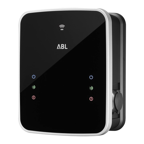
ABL eMH3 User manual

Article No.: 0301599_EN_c
Wallbox
eMH3
Installation manual
EN

| Contact
II
T
h
i
n
k
b
e
f
o
r
e
y
o
u
p
r
i
n
t
Contact
ABL SURSUM
Bayerische Elektrozubehör GmbH & Co. KG
Albert-Büttner-Straße 11
91207 Lauf an der Pegnitz
Germany
+49 (0) 9123 188-0
+49 (0) 9123 188-188
www.ablmobility.de
Customer Service
+49 (0) 9123 188-0
www.ablmobility.de/de/service/support/
Revision: 0301599_EN_c, 13/08/2021

Contents | III
Contents
Contact II
Additional technical information 5
Intended use 5
Information in this document 5
Safety and user information 6
General 6
Safety information 6
User information 7
Introduction to the Wallbox eMH3 9
Identifying your wallbox 9
Components included with the wallbox 10
Accessories 11
Installation 13
Installation site requirements 13
Tools and accessories required 14
Preparing the installation site 15
Preparing and fixing the wallbox in place 17
Electrical connection of the wallbox 18
Data cable connections 19
Commissioning the wallbox 21
Connecting the E3BWLAN 23
Installing and connecting the E3BLTE1 25
Axing the label in accordance with
DIN EN 17186-2019 28
Configuring the Wallbox eMH3 29
Stand-alone operation of a Controller wallbox 29
Stand-alone operation of an Extender wallbox 29
Operation and address allocation in a
group installation 29
Configuration via software 31
Data cable connection with the computer 32
Set-up via Charge Point Administration
application 33
Setting up data communication 36
Setting up an OCPP backend 39
Completing the set-up 40
Manual RFID card administration 40
Charging procedure 43
Error resolution and maintenance 46
Identifying errors 46
General operational malfunctions 51
Checking the internal RCCB 52
Taking the Wallbox eMH3 out of operation 53
Maintenance 54
Appendix 55
Technical specifications 55
Standards and guidelines 60
Trademarks 60
Data cable recommendations 60

Additional technical information | 5
Additional technical information
Additional technical information is required to install your wallbox on one of the separately available mounting poles,
as well as regarding further accessories. It is contained in separate documents.
In addition, the technical data for your wallbox are collated in product-specific data sheets. You can download these
documents from the ABL website using the following link:
https://www.ablmobility.de/en/service/downloads.php
NOTE
Displaying the additional information on a computer, tablet or smartphone
Additional technical information is made available in the Portable Document Format (PDF).
To display PDF files, you need the free Adobe Acrobat Reader or comparable software.
You can find further information about our product range, as well as about separately available accessory compo-
nents on our website at www.ablmobility.de. Please visit:
https://www.ablmobility.de
Intended use
Our Wallbox eMH3 is the ideal solution for group installations in company or hotel carparks. Available with one (Sin-
gle) or two (Twin) charge points, and as stand-alone or Controller-Extender variants. You can also choose between
versions with charging cable or charging socket.
Information in this document
This document explains how to install, configure and commission the Wallbox eMH3: It is recommended that all
working steps described in this document are carried out by a qualified specialist electrical contractor only.
User Specialist electrical
contractor
Installation manual (this document)
Additional technical information
Data sheets
Operating manual
ABL Configuration Software manual

| Safety and user information – General
6
Safety and user information
General
This manual describes all working steps required to install and/or operate the product it concerns.
Certain sections of this manual are specially formatted for quick and easy reference.
Descriptions listing equally valid options are indicated by bullet points.
1 Descriptions listing operating steps are numbered in chronological order.
DANGER!
Indicates life-threatening electrical voltages
Sections marked with this symbol indicate electrical voltages that present a danger of loss of life or grievous
bodily injury.
Actions marked with this symbol must not be carried out under any circumstances.
WARNING!
Indicates important actions and further hazards
Sections marked with this symbol indicate further hazards that may result in damage to the product or to other
connected components.
Actions marked with this symbol must be carried out with special care.
NOTE
Indicates important information for operation or installation
Sections marked with this symbol indicate further important information and features necessary for successful
operation.
Actions marked with this symbol should be carried out as required.
Passages marked with this symbol contain valuable additional information.
Safety information
The safety notices serve to ensure the proper and safe installation, as well as subsequent safe operation of the device.
DANGER!
Violation of the safety information
Disregard of or actions contrary to the safety information and instructions contained in this manual may lead to
electric shock, fire, severe injury and/or death.
Please pay attention to the following points:
Please read this manual carefully.
Heed all warnings and follow all instructions.
Keep this manual in a safe place where it can be accessed at all times: The contents of this manual, and the
safety notices in particular, must be available to all users of the product.
Only use accessories intended and sold for the product by ABL.
Only use charging cables that comply with the IEC 61851 standard.
Do not install this device in close vicinity to running water, water jets or areas subject to flooding.
The product must not be installed in explosive atmosphere areas (EX areas).

Safety and user information – User information | 7
Mechanical installation should be carried out by qualified specialist personnel.
Electrical installation and testing must be carried out with reference to local rules by a qualified specialist
electrical contractor, who, on the basis of their specialist training and experience, as well as their knowledge of
the relevant standards, is able to assess and carry out the working steps described in this manual and recognise
potential hazards.
WARNING!
Notification or approval requirement for charging stations
Please note that electrical grid operators, energy suppliers or national regulations may require notification of or
approval for the installation or operation of a charging station.
The product must only be operated after final approval by a qualified specialist electrical contractor.
In case of installation faults, or malfunctions that can be traced back to faulty installation, always contact the
contractor who carried out the installation first.
The product must not be covered with stickers or other objects or materials.
No liquids or receptacles containing liquids must be placed on the product.
Please note that operating a radio transmitter in the immediate vicinity (< 20 cm) of the product may lead to
malfunctions.
This device is not intended to be used by persons (including children) with limited physical, sensory or mental
abilities or lack of experience and/or knowledge, unless they are supervised by someone responsible for their
safety or have received instructions on how to use the device.
Children must be supervised so that they do not play with the device.
Do not under any circumstances make alterations to the product. Any disregard of this instruction represents a
safety risk, fundamentally breaches the guarantee provisions and may void the warranty with immediate effect.
Malfunctions affecting the safety of persons, connected electric devices or the device itself must be resolved by a
qualified specialist electrical contractor.
Should one of the following malfunctions occur, please contact the specialist electrical contractor who has carried
out the installation of your wallbox and accessories:
yThe product housing has been damaged mechanically, or the housing cover has been removed or can no longer
be closed.
ySufficient protection against splashing water and/or foreign objects is no longer provided.
yThe product does not function properly or has been otherwise damaged.
User information
Ensure that the rated voltage and rated current of the product comply with the parameters of your local electricity
grid and that the rated output is not exceeded during operation.
Local safety regulations regarding the operation of electrical devices for the country in which you operate the
product always apply.
To disconnect the product completely from the electricity grid, the power supply must be interrupted using the
upstream safety switches and fault current protection devices (if present) in the domestic power distribution.
Never operate the product in a confined space.
Ensure that the product can be operated without any strain pulling on its components.
Make sure that the product is always closed and locked when in use. All authorised users must be aware of the
'unlock' position of the key.
You must under no circumstances make any changes to the housing or the internal wiring of the device: Any
disregard of this instruction fundamentally breaches the guarantee provisions and voids the warranty with imme-
diate effect.
Only have the product repaired by a qualified specialist electrical company.

| Safety and user information – User information
8
WARNING!
Proof of professional qualification
In order to carry out repairs on or exchange electrical components, proof of completion of an ABL training course
may be required: For this purpose, please contact ABL technical support (see "Contact" on pageII).
NOTE
Changes to functions and design features
Please note that all technical details, specifications and design characteristics of the product may be changed
without prior notice.

Introduction to the Wallbox eMH3 – Identifying your wallbox | 9
Introduction to the Wallbox eMH3
Congratulations on the purchase of your new Wallbox eMH3 by ABL. Our Wallbox eMH3 is the ideal solution for
group installations in company or hotel carparks. Available with one (Single) or two (Twin) charge points, and as
stand-alone or Controller-Extender variants. You can also choose between versions with charging cable or charging
socket.
The Controller and Extender variants of the Wallbox eMH3 are also available as a bundle with backend solutions by
reev, which offer an intuitive interface for the administration and invoicing of all charging operations.
Further information on technical data is available in the appendix from page55.
Identifying your wallbox
The model variant of the Wallbox eMH3 can be unambiguously identified on
the rating plate located on the inside of the housing cover. Please verify the
information listed below on the rating plate.
The following information is especially relevant:
Model number and indication of product category
(Controller or Extender)
External power supply
AModel number and category
(Controller or Extender) FIndication of type/production series
(3W or Wallbox eMH3) K'Read instructions' advice
BPower supply data GManufacturer and manufacturer's
address LCE label
CAmbient temperature range HManufacturer's logo MBarcode/serial number
DDegree of protection (housing) IDataMatrix code/product number NDate printed
EStandards JDisposal advice
For calibration law compliant wallboxes, additional information is provided on the rating plate:
10000510
2021-05-04
3WXXXX00484
IN 3x230/400V 50Hz 32A
OUT 2x11kW/22kW
Class A kWh EN50470-3
-25°C bis 40°C
IP54
IEC 61851-1
IEC 61439-7 ACSEV
Typ: 3W / Wallbox eMH3
3WXXXX
Controller+
MADE IN GERMANY
ABL SURSUM Bayerische Elektrozubehör GmbH & Co. KG
Albert-Büttner-Straße 11 • D-91207 Lauf / Pegnitz
VDE-NNNNNNNN
036
10000510
2021-05-04
3WXXXX00484
~230/400V 50Hz 32A
-25°C bis 40°C
IP54
IEC 61851-1
IEC 61439-7 ACSEV
Typ: 3W / Wallbox eMH3
3WXXXX
Controller
MADE IN GERMANY
ABL SURSUM Bayerische Elektrozubehör GmbH & Co. KG
Albert-Büttner-Straße 11 • D-91207 Lauf / Pegnitz
P
O
S
Q
R
A
E
D
B
G
H
I
J
C
F
K
L
M
N
10000510
2021-05-04
3WXXXX00484
IN 3x230/400V 50Hz 32A
OUT 2x11kW/22kW
Class A kWh EN50470-3
-25°C bis 40°C
IP54
IEC 61851-1
IEC 61439-7 ACSEV
Typ: 3W / Wallbox eMH3
3WXXXX
Controller+
MADE IN GERMANY
ABL SURSUM Bayerische Elektrozubehör GmbH & Co. KG
Albert-Büttner-Straße 11 • D-91207 Lauf / Pegnitz
VDE-NNNNNNNN
036
10000510
2021-05-04
3WXXXX00484
~230/400V 50Hz 32A
-25°C bis 40°C
IP54
IEC 61851-1
IEC 61439-7 ACSEV
Typ: 3W / Wallbox eMH3
3WXXXX
Controller
MADE IN GERMANY
ABL SURSUM Bayerische Elektrozubehör GmbH & Co. KG
Albert-Büttner-Straße 11 • D-91207 Lauf / Pegnitz
P
O
S
Q
R
A
E
D
B
G
H
I
J
C
F
K
L
M
N

| Introduction to the Wallbox eMH3 – Components included with the wallbox
10
OClass of accuracy QNumber of digits SClass of protection II symbol
PMetrological mark RBMP number (sample device
testing certificate)
NOTE
Explanation of calibration law compliance
Calibration law compliance means that sets of measurement data for each charging procedure are saved perma-
nently. According to the legal regulations applicable in Germany, the electric energy consumed at public charging
stations must be billed in compliance with calibration law.
NOTE
Labelling for calibration law compliant products
To indicate calibration law compliance, the product category of calibration law compliant charging stations is ex-
tended by a 'plus' symbol.
Calibration law compliant Controller charging station: Controller +
Calibration law compliant Extender charging station: Extender +
Components included with the wallbox
The product is delivered including the following components:
Wallbox eMH3 including mounting
plate, 1pc Triangular key, 1pc
× 2
× 1
TX40 wafer head screws,
8×60mm, 4pcs
TX25 wafer head screws, 6×25mm,
4pcs
Wall plugs 10×50mm, 4pcs Cable grommets, 3pcs
× 2
× 1
× 2
× 1
Large strain relief incl. screws, 1pc
× 2
× 1
Small strain reliefs incl.
screws, 2pcs
× 2
× 1
Label for marking the charge points
according to DINEN17186-2019,
1 or 2 pcs (depending on number of
charge points)
yConfiguration for charging sta-
tion with socket
yConfiguration for charging sta-
tion with cable
Operating manual & safety informa-
tion (multilingual), 1pc
Wallbox
eMH3
DE Bedienungsanleitung
Sicherheitshinweise
EN Operating manual
Safety information
ES Instrucciones de uso
Indicaciones de seguridad DK Betjeningsvejledning
Sikkerhedsanvisninger PL Instru kcja obsługi
Wskazówki bezpieczeństwa
FR Mode d‘emploi
Consignes de sécurité EE Käsitsemisjuhend
Ohutusjuhised PT Instruções de Opera ção
Indicações de segurança
IT Istruzioni per l’uso
Avvertenze di sicurezza FI Käyttöohje
Turvallisuusohjeet RO Inst rucţiuni de utilizare
Indicaţii privind siguranţa
NL Gebruiksaanwijzing
Veiligheidsinstructies GR Οδηγίες χρήσης
Οδηγίες ασφαλείας RU Гид пользователя
Сведения о безопас ности
NO Bruksanvisning
Sikkerhetsanvisninger HU Használati út mutató
Biztonsági előírások SI Navodila za upravljanje
Varnostni napotki
SE Bruksanvisning
Säkerhetsanvisningar IS Notendahandbók
Öryggisleiðbeiningar SK Návod na obsluhu
Bezpečnostné upozornenia
BG
Ръководство з а обслуж ване
Указания за безопас ност LT Lietošanas instrukcija
Drošības norādījumi TR Kullanım Kılavuzu
Güvenlik talimatları
CZ Návod na použití
Bezpečnostní pokyny LV Naudojimo vadovas
Saugos nurodymai UA
Інструкція з експ луатаці ї
Правила техніки бе зпеки
Art. No: 0301598_b
Plug-in jumpers for terminating data
bus, 6pcs
Stand-alone variants of the eMH3 also include:
Teach-In tag card, 1pc ID tag cards, 5pcs
Introduction to the Wallbox eMH3 – Accessories | 11
Bundled variants of the eMH3 also include:
reev onboarding letter, 1pc
(Controller/Controller+ only) reev RFID card, 2pcs
QR code stickers, 1 or 2 pcs
(depending on number of charge
points)
Controllers only: LTE USB stick with
SIM card (preconfigured), 1pc
LTE
NOTE
Checking the components included
Check immediately after unpacking whether all components are included: should any components be missing,
please contact the dealer from whom you purchased the wallbox.
Accessories
The following accessories for the Wallbox eMH3 are available separately:
CONFCAB
Configuration kit for connecting all ABL charging stations to a Windows PC for
configuration via specific software applications by ABL
LASTMZ1
External energy meter for connection to a Controller charging station or exter-
nal control unit
LASTMZ2
Coil sensors for connection to the energy meter LASTMZ1
E017869
For all eMH3 model variants, except bundle products: Set of ID tag cards (5pcs)
to extend user pool
LAK32A3
Type 2 charging cable according to IEC 62196-2, up to 32A 240/415VAC,
3-phase, length ca.4m
LAKC222
Type 2 charging cable according to IEC 62196-2, up to 20A 240/415VAC,
3-phase, length ca.7m
LAKK2K1
Type 2 to Type 1 adapter cable according to IEC 62196-2, up to 32A 230VAC,
single phase, length ca. 4m

| Introduction to the Wallbox eMH3 – Accessories
12
POLEMH3
Galvanised sheetmetal mounting pole for the outdoor installation of one Wall-
box eMH3, the weather shield WPR36, and up to two cable holders CABHOLD
h = 1,647mm, w = 405mm, d = 180mm
EMH9999
Precast concrete foundation for installing the mounting pole POLEMH3
h = 650mm, w = 430mm, d = 190mm
POLEMH6
Galvanised sheetmetal mounting pole for the outdoor installation of two Wall-
boxes eMH3, two weather shields WPR36, and up to four cable holders CAB-
HOLD
h = 1,623mm, w = 410mm, d = 360mm
EMH9996
Precast concrete foundation for installing the mounting pole POLEMH6
h = 420 mm, w = 420 mm, d = 420 mm
WPR36
Weather shield for installation on an exterior wall or the mounting pole
POLEMH3
h = 142mm, w = 515mm, d = 285mm
CABHOLD
Cable holder with charging plug receptacle for installation on an exterior wall or
the mounting poles POLEMH1/2/3
h = 187mm, w = 76mm, d = 105mm
E3BLTE1
LTE accessory package with LTE USB stick and adhesive LTE antenna for installa-
tion in Controller wallboxes
LTE
E3BWLAN
USB WiFi dongle for installation in Controller wallboxes
TE001
Multipurpose measuring device for security checks according to IEC/EN61557,
as well as for testing charging stations via the adapter TE002, suitable for TN,
TT, and IT protective earthing systems
TE002
EVSE and vehicle simulation adapter according to IEC 61851 for checking the
function and electrical safety of charging stations
N PE
L1 L2 L3
You can find further information on ABL charging stations and accessories at www.
ablmobility.de.

Installation – Installation site requirements | 13
Installation
It is recommended to have the entire installation of the wallbox carried out by a qualified specialist electrical con-
tractor.
DANGER!
Dangerous electrical currents
Electrical installation, as well as final testing and certification for operation must be carried out by a qualified
specialist electrical contractor, who, on the basis of their specialist training and experience, as well as their
knowledge of the relevant standards, is able to assess and carry out the working steps described in this manual
and recognise potential hazards.
NOTE
Identical installation for Single and Twin variants
The Wallbox eMH3 is available as a Single (one charge point) or Twin (two charge points) variant. In principle, in-
stallation and commissioning are identical. However, the working steps described may need to be applied to both
charge points.
Installation site requirements
Your wallbox is suitable for outdoor use. Please note, however, that the permissible ambient conditions (see "Technical
specifications" on page55) must be adhered to in order to guarantee the functionality of your wallbox at all times.
The installation site must be freely accessible.
The mounting surface must be level and solid.
The mounting surface must measure at least 492×400mm
(height x width).
400 mm
492 mm
The installation height should be between 120 and 140cm
(ground to bottom edge of housing).
120 ~ 140 cm

| Installation – Tools and accessories required
14
Minimum distances to other technical installations must be
observed.
A minimum distance of 50cm is recommended.
Ideally, the installation site should provide a ready connection
to the electricity grid. Otherwise, a separate power supply
cable must be installed.
In order to operate group installations, suitable data cables
must also be installed in the installation site (see also "Prepar-
ing and fixing the wallbox in place" on page17 as well as
"Data cable connections" on page19).
Tools and accessories required
For mechanical installation, you will need the following components included with the wallbox:
Mounting plate, 1pc TX40 wafer head screws,
8×60mm, 4pcs
Wall plugs 10×50mm, 4pcs Triangular key, 1pc
× 2
× 1
TX25 wafer head screws,
6×25mm, 4pcs Cable grommets, 3pcs
× 2
× 1
× 2
× 1
Large strain relief incl. screws,
1pc
× 2
× 1
Small strain reliefs incl.
screws, 2pcs
× 2
× 1
Plug-in jumpers for terminating
data bus, 4pcs
In addition, you will need the following tools:
Electric drill Bit (Torx T20)
10 mm ∅drill bit suitable
for the respective mounting
surface
Pencil
Spirit level Tape measure

Installation – Preparing the installation site | 15
Screwdriver (Phillips head) Screwdriver (TX 25)
Screwdriver (TX 40) Hammer
Pliers Utility knife
Wire stripper Multi-purpose installation
tester
Vehicle simulation adapter N PE
L1 L2 L3 Voltage tester
Preparing the installation site
As a matter of principle, the electrical supply cable in the domestic power distribution must be switched off for the
entire duration of mechanical and electrical installation. The connection to the power grid must only be made live for
the purpose of commissioning, after electrical installation is complete.
DANGER!
Dangerous electrical currents
Always observe the 5 safety rules:
1Cut power source
2Secure all cut-off devices
3Verify absence of voltage
4Ground and short-circuit
5Cover or bar access to adjacent components under voltage
Proceed as follows:
1 Using the spirit level, align the mounting plate level
and plumb on the mounting surface.
2 With the pencil, mark the fixing points in the
mounting position.

| Installation – Preparing the installation site
16
3 Pre-drill the marked fixing points with the electric
drill and drill bit (∅10 mm).
4 Drive the wall plugs into the fixing points with the
hammer.
5 Prepare the mounting plate for the insertion of the
power supply cable (red) and data cables (blue, if
required).
yInsertion from the top: Insert the cables
through the upper opening into the connection
area of the mounting plate and secure the supply
cables using the strain reliefs supplied (power:
large strain relief; data cables: small strain
reliefs).
yInsertion from the back: Drill through the
pre-stamped inlets in the connection area and
insert the cables. In this case you do not need
strain reliefs.
6 Insert the cables through the mounting plate and fix
the mounting plate to the four fixing points using
the four TX40 wafer head screws included.
7 Use a screwdriver or the electric drill with a suita-
ble bit.

Installation – Preparing and fixing the wallbox in place | 17
Preparing and fixing the wallbox in place
Continue to prepare the wallbox:
8 Open the housing cover of the wallbox using the
triangular key and lower it.
T
T
T
9 Loosen the screw holding the internal electronic
components cover in place using the screwdriver
(Torx 20) and put it aside.
yKeep the screw in a safe place.
METER
M
E
T
E
R
C
N
T
R
L
CONTROL
CONTROL
METER
10 Use the utility knife to cut an opening for the pow-
er supply cable into the large rubber grommet, and
then insert it into the housing base.
yInsert the two smaller grommets into the hous-
ing base.
yFor wiring up group installations, you must also
make cuts into the two smaller grommets for the
data cables (see "Data cable connections" on
page19).
METER
M
E
T
E
R
C
N
T
R
L
CONTROL
CONTROL
METER
11 Insert the power supply cable into the housing base
through the large rubber grommet.
yFor wiring up group installations, you must also
insert the data cables into the housing base
through the small grommets.
METER
M
E
T
E
R
C
N
T
R
L
CONTROL
CONTROL
METER

| Installation – Electrical connection of the wallbox
18
12 Fix the wallbox to the mounting plate using the four
TX25 wafer head screws included.
yUse a screwdriver or the electric drill with a
suitable bit.
METER
M
E
T
E
R
C
N
T
R
L
CONTROL
CONTROL
METER
Electrical connection of the wallbox
DANGER!
Dangerous electrical currents
Electrical connection must be carried out by a qualified specialist electrical contractor!
Ensure that the power supply cable remains disconnected from the electricity grid.
Deactivate the RCCB in the wallbox and/or in the domestic power supply.
Proceed as follows to connect the power supply cable inside the wallbox:
1 Cut the supply cable to the required length with
the pliers/wire stripper.
yFor wiring up group installations (see next
section), you must also cut the data cables to
the required length.
METER
M
E
T
E
R
C
N
T
R
L
CONTROL
CONTROL
METER
2 Insert the individual conductors of the power sup-
ply cable into the respective terminals of the RCCB
and tighten them using the screwdriver (torque: 2.5
to 3 Nm).
yEnd ferrules must be fitted on flexible
conductors.
yOperate the spring-loaded mechanism of the
PE terminal and attach the protective earth
conductor.
yUse the connection patterns listed below to
allocate the individual conductors.
METER
M
E
T
E
R
C
N
T
R
L
CONTROL
CONTROL
METER

Installation – Data cable connections | 19
Connection pattern for 3-phase TN system
Designation Conductor colour Marks for
Phase 1 current-carrying conductor Brown L1
Phase 2 current-carrying conductor Black L2
Phase 3 current-carrying conductor Grey L3
Neutral Blue N
Protective earth Green-Yellow PE
WARNING!
Allocation of wire colours
Please note that the colour-coding convention used above is not internationally standardised.
WARNING!
Checking the connection
Please ensure that the conductors that are pre-fixed to the RCCB terminals remain attached correctly after con-
necting the power supply cable.
DANGER!
Dangerous electrical currents
The electronic components of your wallbox will be damaged if a voltage above 250V is applied between the L1
current-carrying conductor and neutral!
Data cable connections
In group installations, a Controller wallbox can control up to 15 Extender charge points after connecting up the data
cables. The Controller wallbox then centrally manages backend communication, charge current distribution, and many
other functions.
For wiring up, the internal bus interfaces of the Controller and Extender variants must be connected serially using
suitable data cables (see "Data cable recommendations" on page60).
Inserting the data cables is described in Step 10 in section "Electrical connection of the wallbox" on page17.
The data bus interfaces are manufactured either as spring terminals (until mid-2021) or established via the RJ45
ports of the Easy2Install interface (called E2I in the following, from mid-2021).
Example of a group installation via E2I interfaces
Extender 2 Extender X
CONTROLLER Extender 1

| Installation – Data cable connections
20
NOTE
Data bus system compatibility
The Wallbox eMH3 bus interfaces are completely downstream compatible. Wiring up spring terminals as well
as E2I interfaces in mixed group installations is possible at any time, as long as the correct terminal allocation is
kept consistent between the two systems. This allocation scheme is illustrated in section "Allocation schematic
from spring terminal to Easy2Install interface" on page61.
WARNING!
Mixed installation of ABL charging stations
Thanks to the common bus formats and interfaces, it is possible to connect up and operate charging stations
from different product series with each other and with the control units 1V0001/2. Configuration/connecting up
follows the schematic as described in the following.
However, please note that connecting up and operating calibration law compliant together with non-calibra-
tion law compliant charging stations in the same group is not possible!
Proceed as follows to connect the wallboxes via the E2I interfaces:
1 Connect the RJ45 plug of the first data cable to one
of the E2I interfaces inside the housing cover of the
Controller wallbox.
TT
MODBUS EN1 MODBUS
METER
M
E
T
E
R
C
N
T
R
L
CONTROL
CONTROL
METER
2 Connect the RJ45 plug of the incoming data cable
with the left hand side E2I interface inside the hous-
ing cover of the first Extender wallbox.
yConnect the RJ45 plug of the outgoing data cable
with the right hand side E2I interface inside the
housing cover of the first Extender wallbox.
TT
MODBUS EN1 MODBUS
METER
M
E
T
E
R
C
N
T
R
L
CONTROL
CONTROL
METER
NOTE
Continuation of the wiring diagram
Connect all subsequent Extender wallboxes according to this method, except for the last Extender wallbox.
Other manuals for eMH3
5
Table of contents
Other ABL Automobile Batteries Charger manuals