Parts and Contents
ey Description Qty
A
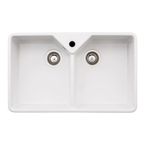
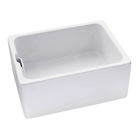
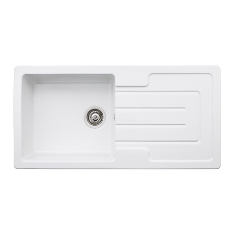
Sink (may differ from
model shown)
1
B Overflow, wastes
and pipework
See included
specification sheet
C Care instructions and
cut-out sizes
1
(dependant on model)
D
Undermount brackets,
bolts and inserts
See included
specification sheet
Installation Instructions
Preparation
1. Take great care when handling this sink. Whilst every effort has been taken to remove sharp edges, the material by
nature may be sharp. We recommend wearing gloves accordingly. Do not lift the product by the waste hole(s) or
tap hole(s).
2. Check the package for completeness, possible defects or any transport damage before installation commences.
Installed faulty product will not be honoured by the warranty.
3. Check that the supporting carcasses and worktop is level left to right and front to back to ensure the correct
drainage of water.
4. Check that the surrounding furniture is the correct size and shape to accept this product and that no plumbing or
wiring may foul the installation.
a. We recommend that all undermount products should be supported under the reverse face with a
substantial braced shelf similar to the example below (when full the sink could weigh up to 40kg). The shelf
should allow for small adjustments in height at each corner and so that it could be disassembled from the
underside in the event that the sink is accidentally damaged.
b. The height of the shelf should be such that when the sink is placed on the shelf the top face rim of the sink
is level with the underside face of the worktop, see the example below.
ey Description
A Surrounding cupboards or end panels
B
Hole for waste connections
(min. recommended dia. 150mm for each
waste, centred to waste position)
C
Supporting shelf
(moisture resistant timber or similar, ensure
framework sits directly under the product)
D Incoming hot and cold supply pipes
Supporting uprights (front & back)
5. If replacing an existing sink, remove this product and clean the surrounding area, ensure the new sink will suit the
existing cut-out size and position, otherwise amend the cut-out size accordingly.
6. Collect the tools you will need to complete this installation.
Installation Instructions Inset
Follow cut out instructions provided, connect overflow and pipe work as instructed. No inset clips are provided so silicone
seal around rim of underside of sink then place onto work surface. Note: Place a heavy object inside bowl to press sink
down to help to keep the sink in place whilst the silicone sets.
Undermount Installation
1. Before creating the cut-out in the worktop carefully plan the positioning of the sink. nsure that the position of the bowl(s),
tap and overflows will not interfere with surrounding units or appliances. The cut-out details are published on the included
specification sheet and are downloadable as CAD file at www.abode.eu to ensure perfect positioning of this product.
Check that the fixing clips will not foul carcass walls or supporting braces.
2. Carefully mark out the cut-out using the provided cut-out drawing or template. Create the sink cut-out in the worktop using
a router or CNC cutter, follow the manufacturers instructions and take care not to chip, crack or scratch the worktop. If
preparing the cut-out in situ cover any open pipework to avoid any debris contaminating the water supply feeds.
IMPORTANT: Due to the hand finished dimensional tolerances of our products we strongly recommend making the cut-out in a scrap piece of
material then offering it against the actual sink to be fitted. The cut-out size should be adjusted to suit the sink tolerances and retested against
the intended product before committing to cutting the final worksurface. The ‘nominal’ suggested cut-out size will align the cut-out edge with
the bowl edge outer radius, the offset from the bowl can be adjusted to overhang or be set back according to personal taste but this may
interfere with installation or the correct usage of sink accessories.
3.
When creating the cut-out aperture you should also create a series of
holes in the reverse face of the worktop to accept the undermount
bracket inserts. The holes should be sized and positioned away from the
edge of the sink as shown in Fig 1. All brackets supplied should be used
and spaced equally around the perimeter. Where the sink has long and
short sides more brackets should be used on the longer sides.
Note: Suggested Ø‘A’= 8mm (wood or similar) else Ø‘A’= 10mm
Fig 1.
4. Fill the reverse face bracket holes with 2 part epoxy adhesive. Push (non
wooden worktops) or screw (wooden worktops) the inserts fully into the
holes, let the adhesive cure before any further assembly.
Note: If screwing in the inserts; use the bolt inside the insert to help drive
the insert in, as shown in fig 2. Unscrew the bolt once the insert is securely
in the hole leaving the insert behind.
Fig 2.
5. Clean the outside rim of the sink and the worktop underside to remove
any dirt or grease, allow to dry. Apply a continuous generous bead of
good quality silicone onto the rim around the upper perimeter of the sink
as shown in fig 3.
Fig 3.
6. Place the sink down squarely onto the rear face of the worktop and flush
to the cut-out edge. Using the ‘U’ shaped brackets and bolts loosely
clamp the sink to the worktop underside as shown in fig 4.
Tighten the brackets in an order similar to that shown in fig 5. From the
top face of the worktop check that the sink position is aligned to the cut-
out before tightening the ‘U’ brackets down fully.
7. Install the tap to the worktop according to the manufacturer’s instructions. nsure the tap is secure as later access may be
obstructed by the sink or plumbing. We recommend long flexible tap connectors to help future maintenance.
8. Install the basket strainer waste kit(s) and overflow(s) according to the manufacturer’s instructions.
9. Place the worktop, sink and tap carefully onto the kitchen carcases.
Where possible apply a 2
nd
bead of silicone around inside of the sink and
worktop joint as shown in Fig. 6.
Any excess silicone can be cleaned away using a proprietary silicone
cleaner. Allow the silicone to dry.
Fig 6.
10. Adjusting the supporting shelf at a the corners to ensure the weight of the sink is supported but that it does not excerpt
pressure on the worktop causing it to flex or bow upwards.
11. Attach the sink connecting pipework to the waste kit(s) according to the manufacturer’s instructions.
After installation
1. If the sink has a protective plastic film coating this should be removed now, clean the sink using the attached care advice ready
for use.
2. Check the sink is flat to the worktop, straight and level; pour a small amount of water onto the drainer to check for drainage.
3. Close the plug(s) in all bowls fill the sink with water below the overflow, check the water does not leak through or around the
waste(s).
4. Close the plug(s) in all bowls fill the sink with water above the overflow, check the water exits though the overflow and does not
leak from the overflow system.
5. Open the plug(s) and let water drain from the bowls, check the connecting pipework does not leak.
6. We recommend once fully set, the silicone seal should be checked for water tightness and rechecked periodically. If the sink is
not to be used for a period after installation, cover the sink and tap to protect them from accidental damage during further
surrounding installation work.
Ø‘A’= 8 - 11mm
(adjust according
to material, test on
Fig 4. Fig 5.
Silicone
bead here

