Parts and Contents:
Key Description Qty
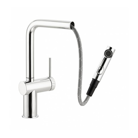
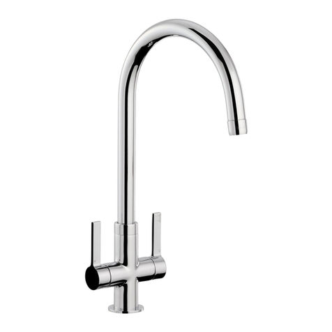
A Spout body 1
B Spout base plinth 1
C Upper seal 1
D Cold flexi tail 1
E Hot flexi tail 1
F Fixing stud 1
G Lower seal 1
H Metal horseshoe 1
I Fixing nut 1
J Rubber dust ap 2
K Grub s rew 2
L Handle 2
M Upper de orative over 2
N Lower de orative over 2
O Base plinth 2
P Upper seal 2
Q Valve body 2
R Lower seal 2
S Bla k fixing nut 2
1
½ BSP adaptor 1
2
M15 adaptor 1
3
15mm washer 1
4
Nylon pull out hose ½” 1
5
Fixing nut 1
Metal washer 1
7
Rubber washers 2
8
Sprayhead body 1
Pull out hose nut 1
10
Rubber washer 1
11
Non return valve (internal to
1
12
Sprayhead 1
Installation Preparation:
All parts should be removed from their pa kaging and inspe ted for any transport damage prior to installation. You should
he k you have the required hot and old supply pressure also.
Before installing the new mixer it is essential that you thoroughly flush through the supply pipes in order to remove any
remaining solder, swarf or impurities from your system. Failure to arry out this simple pro edure ould ause problems or
damage to the workings of the mixertap.
We re ommend installing parti le filters and isolation valves to both the hot and old feed pipes in an a essible position.
This will help to prevent premature failure of the valves and ease any future maintenan e.
Shut off your water heating system and ensure that your mains stop o k is losed. Open the lowest hot and old taps in the
house and allow the water to run until the old-water storage tank and pipes are fully empty. Please note, the hot water
storage ylinder (if appli able) may remain full.
This mixertap requires a 4 x 35∅mm tap holes and the tap entre spa ing is 100-260mm. If repla ing an existing tap, remove
the tap & lean the end of the feed pipes using wire wool the tap hole area should be free from dirt and sealant.
Loosely position the tap and tail pipes to he k if any alteration to the existing pipework is required, if this is the ase do this
now.
If pla ing the tap or spray through a worktop for example the taphole should be sealed in a ordan e with the worktop
manufa tures instru tions, you should pay parti ular are that the seal between the worktop and the tap is orre tly
seated.
The installation of this produ t should respe t requirement IRN R090.
Installation 3 Part:
1. Before installation it is advisable to he k the alignment of valve (P) so that it is positioned in the off position.
2. Create hole in worktop, diameter between 34 – 40mm.
3. Uns rew and remove (K, L, M, N & O).
4. Pass the top of the valve body (Q) through the tap hole from the underside, ensure that the lower seal (R) and fixing nut (S) are on
the underside of the worktop as shown.
5. Whilst holding valve body (Q) push base plinth (O) and upper seal (P) over top of valve body as shown.
6. S rew lower de orative over (N) loosely onto the top of valve body (Q) making sure base plinth (O) and upper seal (P) are flush
with the top surfa e of the worktop.
7. Whilst adjusting lower de orative (N) by s rewing until suffi ient thread is available, s rew upper de orative over (M) onto top of
valve body (Q).
8. With the valve body (Q) entrally positioned to the tap hole, and whilst holding valve body (Q) using rubber or a soft loth tighten
fixing nut (S) fully using an adjustable basin spanner or similar.
9. Align the handle (L) to the valve (Q) in the off position, then tighten handle (L) into pla e using grub s rew (K) using a 2mm allen
key, then push rubber dust ap (J) into handle (L) as shown.
10. S rew fixing stud (F) onto underside of spout body (A).
11. Conne t flexi tails (D & E) to underside spout body (A).
12. Pass spout body (A), fixing stud (F), flexi tails (D & E), base plinth (B) and upper seal (C) through tap hole from the top of the work
surfa e.
13. Pass lower seal (G) then metal horseshoe (H) onto fixing stud (F) flush with underside of work surfa e.
14. On e in pla e tighten fixing nut (I) whilst holding tap body (A) with rubber or a soft loth.
15. Conne t flexi tails (D & E) to horizontal ½” threads on bottom of valve body (P) as shown.
Installation Independent spray:
1. Push the (upper) rubber seal (7) onto the sprayhead body (8) then pass the sprayhead body (12) through the 4
th
taphole, now pass
the (lower) rubber washer (7), and then metal washer (6) over the sprayhead body (8).
2. With the sprayhead body (8) entral to the 4
th
taphole, tighten fixing nut (5) onto sprayhead body (8) to fix its position.
3. S rew the hose nut (9) onto the sprayhead (12) ensuring that rubber seal (10) is present in the joint.
4. Pass the pull out hose (4) through the top of the sprayhead body (8), s rew the pull out hose (4) to the M15 adaptor (2) ensuring that
15mm washer (3) is present in the joint.
5. S rew the ½” adaptor (1) to the old water supply pipe. Nb. we re ommend an additional servi e valve on the spur to ontrol the
spray flow rate.
After Installation:
On e you have visually he ked the installation of the new tap and all onne tions, ensure that all other fittings are losed
ex ept the new tap whi h should be left open. Turn on your water heating system and ensure that your mains stop o k is
open. Re onne t both the hot and old water supplies to this fitting. Che k the fun tion of flow and fun tion of hot, old
and mixed water.
Turn off the tap and he k arefully for any leaks around all onne tions on the fitting and adjoining plumbing. If possible
return to the installation after a longer period to double he k for slower leaks. If pressure testing equipment is available
he k the installation to the maximum re ommended pressure.
Clean the tap to remove any marks reated during installation as instru ted then pla e a bag over the produ t to prote t
the tap until it is ready for use. The installation should be periodi ally he ked for damage, if the property is left unattended
for a prolonged period we re ommend isolating water supplies.
Care Instructions For Your Kitchen Sink Tap:
To maintain the appearan e of this produ t, ensure that it is regularly cleaned only using a
clean, soft damp cloth. A solution of warm water and a mild liquid detergent may be used
where ne essary, and then the fitting rinsed thoroughly and wiped dry. Any other cleaning
action will invalidate your warranty. If the mixertap has a diffuser it should be uns rewed and
leaned periodi ally in water.
Abrasive leaners, s ouring leaners and a idi leaners must not be used under any
ir umstan es. Avoid onta t with all solvents (in luding hlorinated solvents, ketones or
a etones as these may result in surfa e deterioration or et hing). Also avoid onta t with any
harsh household hemi als su h as oven leaners, drain leaners, rust removers, paint strippers
and toilet bowl leaners, bar keepers friend or Brasso.
