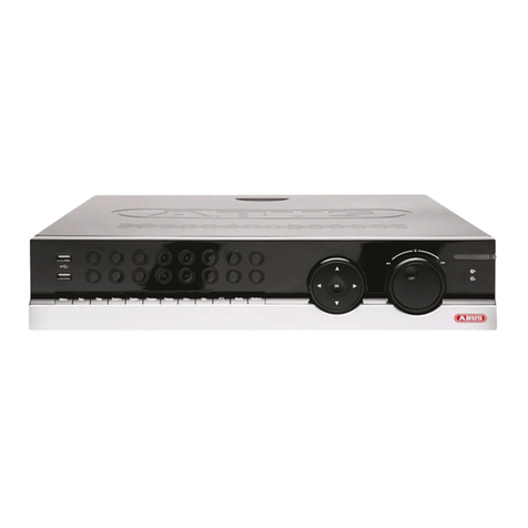
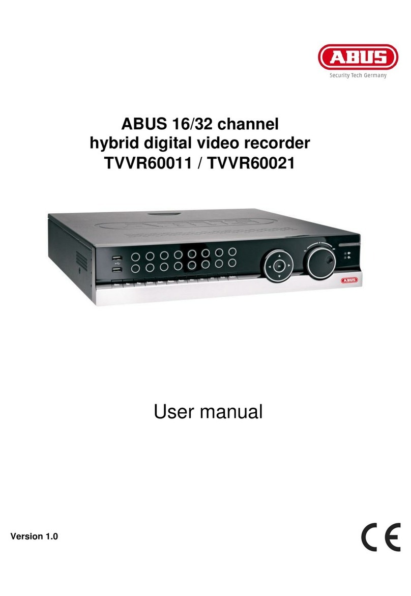
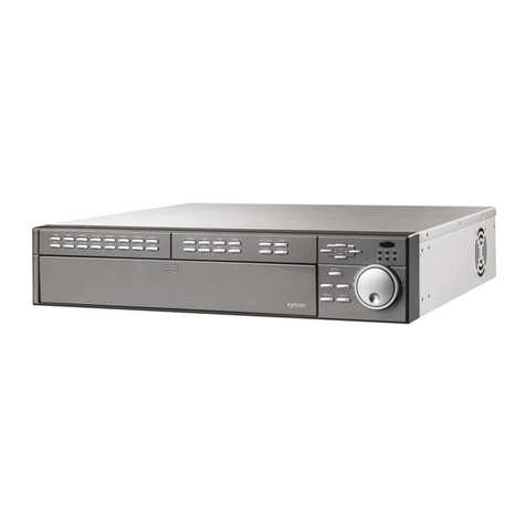
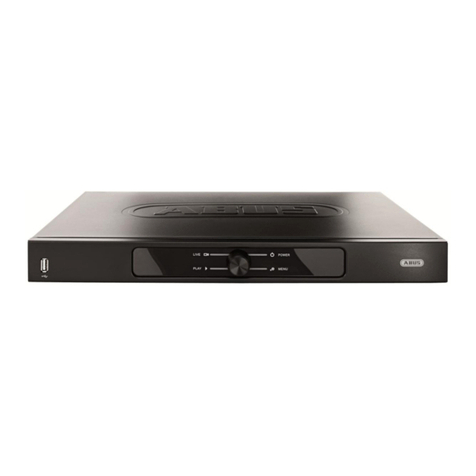
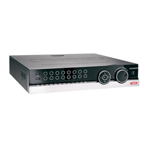
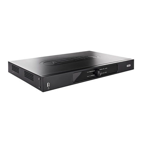
Abus Eytron JPEG2000 User manual

Eytron JPEG2000 Dual
Codec DVR
User manual
TV8931-TV8933
Version: 1.0, 03/2008

49
Contents
1. Preface ................................................................................................................ 50
2. Scope of delivery................................................................................................ 51
3. Features .............................................................................................................. 51
4. Precautions......................................................................................................... 52
5. System Design ................................................................................................... 53
5.1 Front Panel............................................................................................... 53
5.2 Rear Panel ............................................................................................... 55
5.3 Remote Controller.................................................................................... 56
6. Installation............................................................................................................. 57
6.1 Camera installation................................................................................... 57
6.2 Monitor and SPOT Monitor installation..................................................... 57
6.3 Sensor and Alarm installation................................................................... 58
6.4 PTZ camera installation............................................................................ 59
6.5 HDD installation........................................................................................ 60
6.6 Mouse installation..................................................................................... 60
6.7 Power plugging......................................................................................... 60
7. Operation ............................................................................................................ 61
7.1 Display...................................................................................................... 61
7.2 Channel selection..................................................................................... 62
7.3 PIP (Picture in Picture) view..................................................................... 63
7.4 Freeze view.............................................................................................. 63
7.5 View in sequence ..................................................................................... 63
7.6 Zoom in view............................................................................................ 64
7.7 Key lock.................................................................................................... 64
7.8 Playback................................................................................................... 64
7.9 Search...................................................................................................... 64
7.10 Mouse operation..................................................................................... 66
8. OSD (On-Screen-Display) Menu...................................................................... 68
8.1 LOG-IN..................................................................................................... 68
8.2 System menu ........................................................................................... 68
8.2.1 DISPLAY SETUP................................................................................... 69
8.2.2 CONFIGURATION................................................................................. 70
8.2.4 BACK-UP .............................................................................................. 81
8.2.5 EXTERNAL DEVICE............................................................................. 83
8.2.6 FACTORY DEFAULT............................................................................. 89
8.2.7 LANGUAGE .......................................................................................... 89
9. Software & DDNS Server.................................................................................. 89
10. Possible recording time................................................................................... 90
11. Specifications ................................................................................................... 91
12. FAQ (Frequently asked questions) ................................................................ 92
50
1. Preface
Dear Customer,
Thank you for purchasing this Eytron digital recorder. You made the right decision in
choosing this state-of-the-art technology. This product complies with the current standards
of domestic and European regulations. The CE has been proven and all related
certifications are available from the manufacturer (www.security-center.org) upon request.
To maintain this status and to guarantee safe operation, it is your obligation to observe
these operating instructions!
This digital recorder is used in combination with connected video signal sources (B/W and
colour cameras) and video output devices (monitors) for object surveillance. It can
simultaneously record signals from up to 16 connected video sources, depending on the
model. With the help of the built-in CD drive or use of the USB-Port, you can save image
data, transfer it to a PC and view and archive complete video sequences. Thanks to H.264
video compression for network streaming, the recorder can easily be accessed from any
point in the world.
Data storage is subject to local national data-protection guidelines. During installation, draw
your customers’ attention to the existence of these guidelines.
© Security-Center GmbH & Co. KG, March 2008
Every effort has been made to ensure that the contents of this manual are correct.
However, neither the authors nor Security-Center GmbH & Co. KG accept any liability for
loss or damage caused or alleged to be caused directly or indirectly by this manual. The
contents of this manual are subject to change without notice.

51
2. Scope of delivery
•Eytron JPEG2000 Dual Codec DVR
•Remote control
•Batteries
•Power supply
•Power cable
•Software CD
•Installation instructions
3. Features
This Eytron digital recorder has following functions:
•Dual Codec: JPEG2000 image recording + H.264 network streaming
•Simultaneous recording and display of up to 4/8/16 video signal sources
(B/W and colour cameras)
•High resolution display recording (720 x 288 pixels, PAL)
•Adjustable recording quality level
•Adjustable recording speed
•Manual, scheduled and event-controlled recording with integrated motion sensor
•Video signal loss display
•4/8/16 looped-through video inputs
•2 video outputs (Monitor and spot monitor)
•4/8/16 alarm inputs, 1 alarm output
•Adjustable display formats
•Ethernet port for LAN and WAN
•CD-R writer and USB-Port for image export
•SATA HDD support
•Multilingual on-screen menu
•RS-485 port for controlling speed-dome cameras

52
4. Precautions
The digital recorder and connected components must be kept free of moisture (cellars and
similar surroundings are to be strictly avoided). Use of this product for other than the
described purpose may lead to damage of the product. Other hazards such as short-
circuiting, fire, electric shock, etc., are also possible. The recorder is designed for operation
with a transformer for main electricity at 230 Volt AC / 50 Hz.
No part of the product may be changed or modified in any way. Connection to the public
power network is subject to country-specific regulations. Please be aware of applicable
regulations in advance.
To avoid fire and injury, please observe the following:
•Securely fasten the device at a dry location in the building.
•Make sure there is sufficient ventilation.
•Do not expose the device to temperatures less than 5°C or more than 40°C.
•The device is designed for indoor use only.
•The maximum humidity must not exceed 90% (non-condensing).
•Ensure that the voltage is disconnected when performing work on the device.
Please observe the following regulations to ensure trouble-free operation of your
device:
•The Eytron digital recorder is supplied by a 12V DC transformer. The device should be
connected via a separate fused line to the local 230V AC network.
•Connecting the device to the local mains network is subject to country-specific
regulations.
General:
Improper or careless installation work may lead to faults and poor image quality. The cause
of bad picture quality goes hand in hand with improper cabling. Ensure professional
installation and avoid passive video distributors. Always select the shortest distance
between the camera and the video unit. Therefore please read the instructions very
carefully and follow the installation instructions for lines and components precisely.
The manufacturer reserves the right to make technical modifications at any time.

53
5. System Design
5.1 Front Panel
Description of operating controls
(1) 1/ON - Press for a full screen picture of camera input 1
(2) 2/OFF - Press for a full screen picture of camera input 2
(3) 3/OPEN - Press for a full screen picture of camera input 3
- Open iris (for PTZ camera control only)
(4) 4/CLOSE - Press for a full screen picture of camera input 4
- Close iris (for PTZ camera control only)
(5) 5/NEAR - Press for near focus (for PTZ camera control only)
(6) 6/FAR - Press for distant focus (for PTZ camera control only)
(7) 7/WIDE - Press to enlarge view (for PTZ camera control only)
(8) 8/TELE - Press to reduce view (for PTZ camera control only)
(9) MODE - Press to select a display format
(10) SEQ - Press to enable/disable the sequencing function
(11) PIP - Press to enable/disable the picture-in-picture function
(12) ZOOM - Press to activate the digital zoom function
(13) PANIC REC - Press to start recording
(14) STOP - Press to end the current function and switch to standby mode
(15) + - During programming: press to increase a value
(16) - - During programming: press to reduce a value
(a) 9/SET - Press to define a preset position (for PTZ camera control only)
(b) 10/CLEAR - Press to clear a predefined preset position
(for PTZ camera control only)
(c) 11/GOTO - Press to call the previously saved preset positions
(for PTZ camera control only)
(d) 12/AUTO - Press to activate the auto-scan function (PTZ camera only)
(e) 13/F1 - Press to define user 1 (for PTZ cameras only).
Analogue to (e), press (f), (g) or (h) to define users (2), (3) or (4)
(i) K.LOCK - Press to activate/deactivate the key lock function
(j) PTZ - Press to activate the PTZ control
(k) NEXT - Press for a full screen picture of the next camera input
(l) FREEZE - Press to freeze a picture
(m) PLAY - Press to start playback
In playback mode: Press to change playback direction
(n) SEARCH - Press to search recordings for date, time and event.
(1) (2) (4)(3) (5) (6) (7)
(8) (10)(11)
(12) (13)
(14) (15)
(b)
(a) (c) (d) (e) (f) (g) (h) (i) (j) (k) (l) (m) (n) (o) (p)
(9) (16)

54
(o) MENU - Press to open the OSD menu
(p) J.SHUT - Press to activate the jog-shuttle.
Description of control keys and LEDs
(1) - In playback mode: Press to switch playback from forwards to reverse.
- In programming mode: Press to move the cursor to the left.
(2) - In playback mode: Press to increase playback speed.
- In programming mode: Press to move the cursor up.
(3) - In search mode: Start playback.
- In programming mode: Press to confirm your selection.
- In playback mode: Press to switch playback from reverse to forwards.
- In programming mode: Press to move the cursor to the right.
(5) - In playback mode: Press to increase playback speed.
- In programming mode: Press to move the cursor down
(6) - REC: The LED lights up red during recording.
(7) - FULL: The LED lights up red if the hard disk is full.
(8) - RUN: The LED lights up red when jog-shuttle is used.
(9) - PLAY: The LED lights up green during playback.
(10) - NET: The LED lights up yellow if a LAN connection is active.
(11) - ACTIVE: The LED lights up yellow if an option is activated
(PTZ control, search function, rotating wheel …).
(12) - CD-R Writer
(13) - USB Port for firmware upgrade.
(14) - USB Port USB backup
(15) - Hard disk housing

55
5.2 Rear Panel
Description of rear connectors
4-Channel
8-Channel
16-Channel
(1) - RS485 connection to PTZ cameras
- 4/8/16 sensor inputs and 1 relay output
(2) - Optional VGA output. Gets activated when inserting VGA module TV8934
(3) - Ethernet connection for LAN or Internet access
(4) - Not used
(5) - 4/8/16 BNC-Camera inputs
- 4/8/16 BNC-Camera outputs looped through
(6) - BNC-Monitor output
- BNC-Spot monitor output. This output will show every channel in sequence. If an
alarm is triggered the according camera will be shown.
(7) - DC 12V power input
(8) - Power Switch
(9) - PS/2 connector to connect a mouse

56
5.3 Remote Controller
(1) - Enter or exit Menu
(2) - Choose between different viewing modes
- The Audio button is disabled
(3) - Press to switch to a camera
- Use to enter password
(4) - Press FRZ to freeze live screen
- Press SEQ to start sequence viewing
- Press ZOOM to enlarge picture. Use the direction
buttons to move around.
(5) - Press MODE to select between different multi-screen
views
- Press P/T to control PTZ camera
(6) - Press SEARCH to start playback mode
- Press - / + to decrease or increase value
- Press NEXT to select next PTZ command or select
next camera channel or next spilt screen display
(7) - Press REC to activate emergency record. This
recording will always be at best resolution and in Super
Fine quality
(8) - Press STOP to stop emergency recording and return to
schedule recording or to stop playback and return to
Live mode
(9) - Press PLAY to playback the recording directly
- Press PAUSE to pause playback
- Press REW to fast rewind playback, press again to
adjust speed
- Press FW to fast forward playback, press again to
adjust speed
- Press STEP to show picture by picture during playback
- Press SLOW for slow motion playback, press again to
adjust speed
(10) - Press ENTER to select or adjust menu item
(11) - Press the direction buttons to navigate

57
6. Installation
6.1 Camera installation
Connect the cameras to BNC-
Channels 1-16.
※Please do not start the DVR
before the camera installation
is done.
6.2 Monitor and SPOT Monitor installation
Connect the MONTIOR BNC-Output of the
DVR back panel to the “Video In” port of the
monitor.
Connect the Spot Monitor BNC-Output to a
second monitor. All camera channels will be
shown in sequence, if an alarm is triggered,
the channel will pop up.

58
6.3 Sensor and Alarm installation
4-Channel
8-Channel
16-Channel
D1 – D16
Connect D1 – D16 alarm input and Ground (GND) of corresponding channel with sensor.
Alarm will be triggered once sensor causes short circuit or open circuit.
FUNCTION
1RS485D‐ 6GND11 ALARMD5
2RS485D+7GND12 ALARMD4
3RELAYCOM8ALARMD813 ALARMD3
4RELAYNC9ALARMD714 ALARMD2
5RELAYNO10ALARMD615 ALARMD1
FUNCTION
1RS485D‐ 14 ALARMD11
2RS485D+15 ALARMD10
3GND16 ALARMD9
4RELAYCOM17 GND
5RELAYNC18 ALARMD8
6RELAYNO19 ALARMD7
7GND20 ALARMD6
8ALARMD1621 ALARMD5
9ALARMD1522 GND
10 ALARMD1423 ALARMD4
11 ALARMD1324 ALARMD3
12 GND25 ALARMD2
13 ALARMD1226 ALARMD1
SENSOR
INTERNAL
CIRCUIT

59
Relay Output NO/NC/COM
The alarm output can be NO (Normally Open) or NC (Normally Closed), depending on the
settings in the menu.
- NO + COM are a normally open circuit. Alarm is triggered when the circuit is closed.
- NC + COM are a normally closed circuit. Alarm is triggered when the circuit is
opened.
6.4 PTZ camera installation
Connect the PTZ’s “D+” to the DVR’s “RS 485 D+”, and the PTZ’s “D-“ to the DVR’s “RS
485 D-“. After the connection and the related setup are done, users are able to control the
PTZ camera using the front panel buttons or included software.
NO / NC
COM
POWER
SUPPLY
+12V
GND

60
6.5 HDD installation
Fitting the hard disk
1. Step: Switch off the digital recorder and open the hard-disk slot.
2. Step: Turn the handle carefully to the left and pull the HDD frame carefully out of the
slot. (Keys and fitting screws are contained in the HDD frame.)
3. Step: Push the plastic lock of the HDD frame cover down and push the upper cover
of the HDD frame back.
4. Step: Fix the hard-disk with two screws on the left and two screws on the right of the
HDD frame and then close the frame with the upper cover.
5. Step: Insert the HDD frame back into the slot, push it until engages, and turn
the handle to the right. Now lock the hard disk with the key.
6.6 Mouse installation
Connect mouse to the PS/2 port at rear side in
order to control the DVR by mouse.
It is also possible to use a USB mouse with a
USB->PS/2 converter.
6.7 Power plugging
Insert the adapter to the rear power socket of DVR.
Insert the power cable to the other side of adapter.
Plug in the power cable and
power on the DVR.

61
7. Operation
7.1 Display
1 - Shows in Live mode current time
- Shows in Playback Mode recorded time in playback
2 - Shows in Live mode current date
- Shows in Playback Mode recorded date in playback
3 - Displays the camera title of every channel
4
- Displays the recording quality LOW - HYPER
5
- Displays if a client is connected. Disconnected Connected
6 - Shows in Live Mode the used HDD capacity in percentage
- Shows in Playback Mode the current position of recorded data in percentage

62
7 - Displays the Recording Resolution:
4CH: 50IPS@720X288 (PAL) / 60IPS@720X240 (NTSC)
100 IPS @360X288 (PAL) / 120IPS@360X240 (NTSC)
200 IPS @360X144 (PAL) / 240IPS@360X120 (NTSC)
8CH/
16CH: 100IPS@720X288 (PAL) / 120IPS@720X240 (NTSC)
200 IPS @360X288 (PAL) / 240IPS@360X240 (NTSC)
400 IPS @360X144 (PAL) / 480IPS@360X120 (NTSC)
8 - Displays the current Recording Mode:
Alarm Recording Motion Recording
Continuous Recording
9 - Displays the Recording Status
Emergency Record
Scheduled Record
Recording stopped
7.2 Channel selection
- Press the number button to switch to the corresponding channel for its full screen view.
- Press the Mode button to switch among different split mode displays: 4/6/8/9/13/16 splits.
Push then +/- button to adjust the order in split mode display.

63
7.3 PIP (Picture in Picture) view
- In full screen mode, press “PIP” to enter PIP mode.
- Press “PIP” again to cancel.
7.4 Freeze view
- In a split screen mode, press FREEZE and a number
button to select the corresponding channel to freeze.
Press the number again to cancel freeze.
- In full screen mode, press FREEZE to freeze the
channel, and press FREEZE again to cancel.
7.5 View in sequence
Sequence display of all channels can be activated by pressing the button SEQ. By pressing
the SEQ button again the sequence display will be stopped.
Sequence time is adjustable in system setup.
Freeze

64
7.6 Zoom in view
- Select the channel to be zoomed and press ZOOM to
bring up zoom area. Press ENTER to enlarge this
area. Use the direction buttons to move the enlarged
part.
- Press the ZOOM button again to exit.
7.7 Key lock
- To activate the key lock function, press the “K. LOCK“
button. The word “LOCK” will be shown on the screen
and all buttons will be disabled at this time.
- To unlock, press and hold K.LOCK and enter admin’s
password.
7.8 Playback
Press the PLAY button to start immediate playback or press the SEARCH button to open
the search selection dialog.
To enter Playback or Search mode the admin’s password has to be entered.
7.9 Search
SEARCH
SEARCH BAR
TIME/DATE
EVENT LIST
SELECT MENU ▲▼, & [ENTER]
SEARCH BAR
Here you can search by appointing a
recording percentage. Using Jog-shuttle is a
quick and convenient way to search.
TIME/DATE
Here you can search by appointing a time
and date.
EVENT LIST
Here you can search by selecting an event.

65
SEARCHBAR
SEARCH
[TARGET DATE/TIME]
040%
SELECT: JOG. SHUTTLE
SEARCH: [ENTER], EXIT: [MENU]
Use the Jog-shuttle or +/- keys to select the
recording percentage of the search bar.
Press the “ENTER” button to confirm and
start the playback.
TIME/DATE
TIME/DATE
[START] 2008/08/21 14:10:01
[END] 2008/09/10 12:05:10
INPUT DATE/TIME
21.08.2008 14:10
SELECT: ◄►, EDIT: + -
SEARCH: [ENTER], EXIT: [MENU]
START
Shows the start date and time of the
recording.
END
Shows the end date and time of the
recording.
INPUT DATE/TIME
Enter the appointed time and date to start
playback. Select the time and date by +/-
key to adjust numbers and by ef key to
adjust the cursor position. Press “Enter” to
start playback.
EVENT LIST
EVENT LIST
CH EVENT TIME/DATE 001/009
01 MOT 21.08.2008 14:12:52
01 LOS 21.08.2008 14:11:30
04 ALM 21.08.2008 14:11:08
03 MOT 21.08.2008 14:10:52
SEARCH: [ENTER], EXIT: [MENU]
CH
Shows the channel the event occurred.
EVENT
Shows which kind of event occurred.
Motion detection (MOT), Image lost (LOS)
and Alarm triggered (ALM).
TIME/DATE
Shows at what time and date the event
occurred.
The DVR will automatically store the 1000 newest events in the Event List.

66
7.10 Mouse operation
In order to control the JPEG2000 Dual Codec DVR by mouse, it is necessary to connect the
mouse with the PS/2 port at the rear side of the DVR.
When using the mouse in Live Mode, the mouse can be used as following.
Left Mouse button - Click: To execute
- Double click: Switch to full screen
Right Mouse button - Double click: Display mouse control interface
Mouse wheel - Keep pressed for 2 seconds to hide mouse control interface
Control mouse interface
By double clicking the right mouse button the control interface will pop up.
To change assigned screen division, click left button of mouse once. According to the
different models, screen division can be different.
Icon Left click Right click Icon Left click Right click Icon Left click Right click
REC PLAY SEARCH
PTZ ZOOM FREEZE
PIP SEQ N.A.
K.LOCK MENU NEXT ENTER
PLUS MINUS

67
Control interface in PLAY mode
To start playback press the PLAY icon to switch to playback interface or click on the
"SEARCH" icon to open the search dialog.
Control interface in PTZ mode
To control a PTZ camera by mouse, press the PTZ icon to enter PTZ mode.
Icon Left click Right click Wheel Icon Left click Right click Wheel
Pause
Backward Step play
Slow
backward Adjust speed
Fast
backward Adjust speed Play
Fast forward Adjust speed Slow forward Adjust speed
Pause
forward Step play
Pause
REC Stop
Icon Left click Right click Wheel Icon Left click Right click Wheel
UP
Change
channel
DOWN
Change
channel
LEFT-UP RIGHT-UP
LEFT RIGHT
LEFT-DOWN RIGHT-
DOWN
ZOOM IN ZOOM OUT ZOOM
IN/OUT FOCUS
NEAR FOCUS FAR FOCUS
NEAR/FAR
MENU NEXT Change
Command PLUS MINUS
PRESET
NUMBER+/-
SET
PRESET
Change
channel
GOTO
PRESET
Change
channel
CLEAR
PRESET AUTO SCAN
EXIT PTZ
MODE ENTER
Table of contents
Other Abus DVR manuals

Abus
Abus TVHD800x0 User manual

Abus
Abus TVVR33004 User manual

Abus
Abus eytron TV8901 User manual

Abus
Abus Eytron TV8931 User manual

Abus
Abus TVVR33049T User manual

Abus
Abus TVVR30004 User manual

Abus
Abus TVHD80100 User manual

Abus
Abus TVVR36401 User manual

Abus
Abus HDCC90001 User manual

Abus
Abus TVVR60011 User manual

Abus
Abus HDCC90000 User manual

Abus
Abus TVVR45021 User manual

Abus
Abus TVVR41100 User manual

Abus
Abus TVVR30003 User manual

Abus
Abus TVVR33004 User manual

Abus
Abus HDCC900 2 Series User manual

Abus
Abus eytron User manual

Abus
Abus TVHD80000 User manual

Abus
Abus TVVR50011 User manual

Abus
Abus TVVR40000 User manual