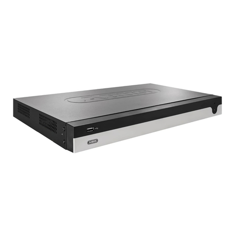
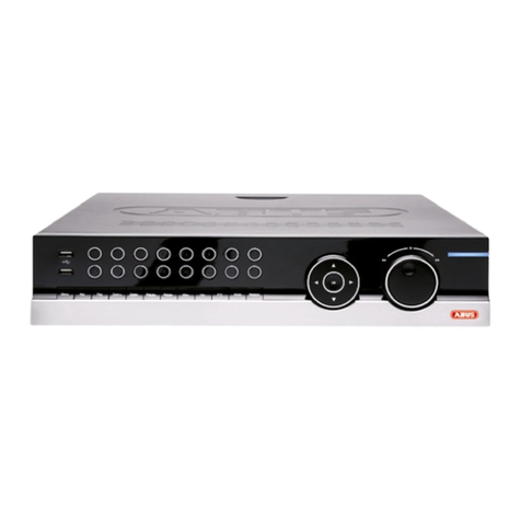
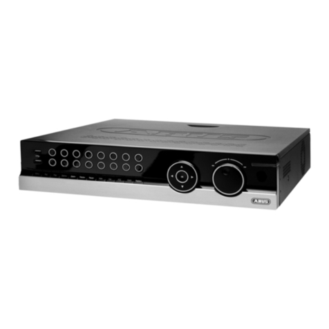
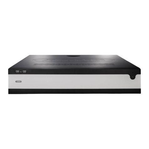
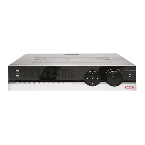
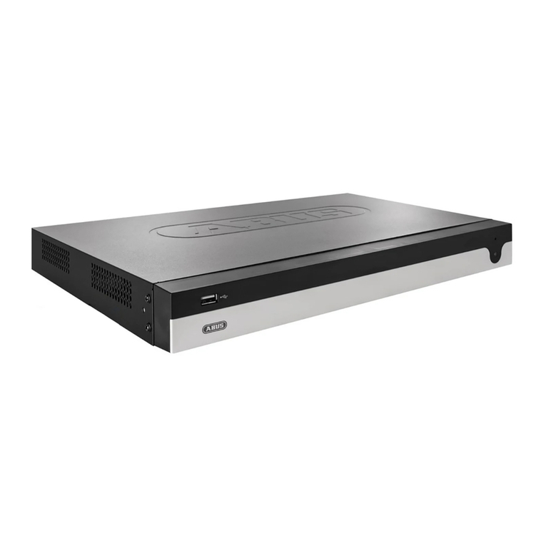
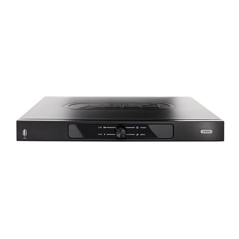
Abus eytron User manual

1
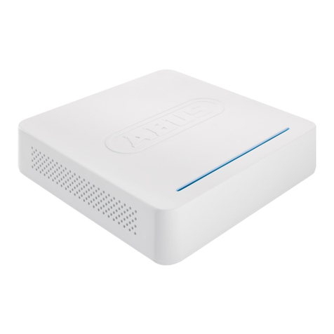
16-channel digital recorder
TV8903
Installation Guide

2
Preface
Dear Customer,
Thank you for purchasing this 16-channel digital recorder. You made the right decision in
choosing this state-of-the-art technology,
which complies with the current standards of domestic and European regulations. The CE has
been proven and all related certifications are available from the manufacturer upon request.
To maintain this status and to guarantee safe operation, it is your obligation to observe these
operating instructions! In the event of questions, please contact your local specialist dealer.
This 16-channel digital recorder is used in combination with connected video signal sources
(B/W and colour cameras) and video output devices (monitors) for object surveillance. It can
simultaneously record signals from up to 16 connected video sources. Data storage is subject
to local national data-protection guidelines. During installation, draw your customers’
attention to the existence of these guidelines. With the help of the built-in CD/DVD drive, you
can save image data, transfer it to a PC, and open it there using special software. You can
also view and archive complete video sequences on your PC.
Precautions
The 16-channel digital recorder and connected components must be kept free of moisture
(cellars and similar surroundings are to be strictly avoided). Use of this product for other than
the described purpose may lead to damage of the product. Other hazards such as short-
circuiting, fire, electric shock, etc., are also possible. The recorder is designed for operation
with a transformer for mains electricity at 230 Volt AC / 50 Hz.
No part of the product may be changed or modified in any way. Connection to the public
power network is subject to country-specific regulations. Please be aware of applicable
regulations in advance.
To avoid fire and injury,
please observe the following:
•Securely fasten the
device at a dry location in
the building.
•Make sure there is
sufficient ventilation.
•Do not expose the device
to temperatures less than
-10°C or more than 50°C.
•The device is designed for
indoor use only.
•The maximum humidity
must not exceed 90%
(non-condensing).
•Ensure that the voltage is
disconnected when
performing work on the
device.
Please observe the following
regulations to ensure
trouble-free operation of
your device.
•The 16-channel digital
recorder is supplied by a
12V DC transformer.
The device should be
connected via a
separate
fused line to the local
230V AC network.
•Connecting the device to
the local mains network is
subject to country-
specific regulations.
General:
Improper or careless
installation work may lead to
faults and poor image
quality. Therefore please
read the instructions very
carefully and follow the
installation instructions for
lines and components
precisely.
The manufacturer reserves
the right to make technical
modifications at any time.

3
Contents
PREFACE............................................................................................................................ 1
PREFACE............................................................................................................................ 2
PRECAUTIONS.................................................................................................................... 2
CONTENTS ........................................................................................................................3
SCOPE OF DELIVERY ........................................................................................................... 4
OVERVIEW ......................................................................................................................... 5
DESCRIPTION.....................................................................................................................5
SYSTEM DESIGN ................................................................................................................. 6
REAR CONNECTIONS.......................................................................................................... 6
DESCRIPTION OF OPERATING CONTROLS ............................................................................ 7
DESCRIPTION OF CONTROL KEYS AND LEDS........................................................................ 9
HARD DISK ...................................................................................................................... 10
FIRST STEPS WITH THE 16-CHANNEL DIGITAL RECORDER .................................................. 11
PROGRAMMING THE 16-CHANNEL DIGITAL RECORDER ..................................................... 15
SYSTEM MENU ................................................................................................................. 16
DISPLAY SETUP.................................................................................................................. 16
CONFIGURATION ............................................................................................................. 17
HDD MANAGEMENT................................................................................................... 17
TIME/DATE SETUP ..................................................................................................... 17
CAMERA SETUP ......................................................................................................... 18
INTERVAL SETUP........................................................................................................ 20
ALARM SETUP............................................................................................................ 20
EVENT POPUP SETUP.................................................................................................. 21
BUZZER SETUP........................................................................................................... 21
PASSWORD SETUP...................................................................................................... 22
SYSTEM INFORMATION .............................................................................................. 23
RECORD SETUP ................................................................................................................. 24
RECORD CONFIGURATION ......................................................................................... 24
SCHEDULE SETUP....................................................................................................... 25
HOLIDAY SETUP......................................................................................................... 25
BACK-UP ......................................................................................................................... 26
EXTERNAL DEVICE............................................................................................................. 27
TCP/IP SETUP ............................................................................................................ 27
RS232C SETUP........................................................................................................... 28
PANTILT SETUP (PTZ control) ..................................................................................... 28
FACTORY DEFAULT............................................................................................................ 29
CLIENT SOFTWARE............................................................................................................. 30
CD-R BACKUP PLAYER SOFTWARE ..................................................................................... 39
TECHNICAL DATA ............................................................................................................. 41

4
Scope of delivery
16-channel digital recorder
Power unit with connection cable
Installation guide
Software CD
Remote control + batteries

5
Overview
•Modern JPEG2000 image compression method
•Simultaneous recording and display of up to 16 video signal sources (B/W and colour
cameras)
•High resolution display (720 x 576 pixels, PAL) and recording (720 x 288 pixels, PAL)
•Adjustable recording quality level
•Adjustable recording speed
•Portable 3.5" quality hard drive
•Manual, scheduled and event-controlled recording with integrated motion sensor
•Video signal loss display
•16 looped-through video inputs and 2 video outputs (monitor and video recorder)
•16 alarm inputs, 1 alarm output
•Adjustable display formats (single, quad display)
•Ethernet port for LAN and WAN
•CD burner for image export
•Multilingual on-screen menu
•RS-485 port for controlling speed-dome cameras
Description
The 16-channel digital recorder is the ideal substitute for an existing video recording
system consisting of an analogue video long-play recorder and multiplexer. The user-
friendly operation and simple programming enable fast installation of the equipment and
simple, intuitive handling. The 16-channel digital recorder simultaneously processes up to
four video signals (FBAS and BAS). The data is stored on the built-in, portable hard disk. The
hard disk is automatically overwritten if this feature is selected. This enables continuous,
loss-free recording of video data in constant high quality over several years. No tape
changing is necessary. If required, individual pictures and complete video sequences can
be transferred to a PC and archived for later use.

6
System design
Rear connections
(1) BNC plug
CAM 1 – CAM
16
Video IN
Connection for video signal sources (B/W and colour cameras)
(2) BNC plug
VCR Video OUT
Port for analogue video recorder
(3) ON/OFF switch
POWER Main switch
Activates/deactivates the digital recorder.
(4) Cable clamp
strip Universal clamp strip
For connecting alarm inputs and outputs and for RS-485
(see name on the rear of the device)
(5) 15-pole plug
VGA Video OUT
For connecting a PC monitor or LCD screen (optional module)
(6) RJ45 plug
ETHERNET Ethernet port
Connection for LAN 10/100 Mbit/s
(7) 9-pole port
RS-232 Serial port
For connecting a PC via RS232-C
(8) BNC plug
LOOP CAM1 –
LOOP CAM16
Video OUT
For exporting camera signals of CAM 1 – CAM 16
(9) BNC plug
MONITOR Video OUT
For connecting a CRT monitor
(10) Voltage
12V DC Voltage input
For connecting an external transformer. Only the transformer
supplied is permitted.
(
5
)
(
6
)
(
7
)
(
8
)
(
9
)
(
10
)
(
4
)
(
1
)
(
2
)
(
3
)

7
Description of operating controls
(1) 1/ON - Press for a fullscreen picture of camera input 1.
- Light on (for PTZ camera control only)
(2) 2/OFF - Press for a fullscreen picture of camera input 2.
- Light off (for PTZ camera control only)
(3) 3/OPEN - Press for a fullscreen picture of camera input 3.
- Open iris (for PTZ camera control only)
(4) 4/CLOSE - Press for a fullscreen picture of camera input 4.
- Close iris (for PTZ camera control only)
(5) NEAR - Press for a fullscreen picture of camera input 5.
Press for near focus (for PTZ camera control only)
(6) FAR - Press for a fullscreen picture of camera input 6.
Press for distant focus (for PTZ camera control only).
(7) WIDE - Press for a fullscreen picture of camera input 7.
Press to enlarge view (for PTZ camera control only)
(8) TELE - Press for a fullscreen picture of camera input 8.
Press to reduce view (for PTZ camera control only)
(9) MODE Press to select a display format.
(10) SEQ Press to enable/disable the sequencing function.
(11) PIP Press to enable/disable the picture-in-picture function.
(12) ZOOM Press to activate the digital zoom function.
(13) REC Press to start recording.
(14) STOP Press to end the current function and switch to
standby mode.
(15) MENU Press and keep pressed until a password query appears on the display.
(16) J.SHUTTLE Press to stop playback.
(a) SET - Press for a fullscreen picture of camera input 9.
Press to define a position (preset) (for PTZ camera control only).
(b) CLEAR - Press for a fullscreen picture of camera input 10.
Press to clear a predefined dome position (preset)
(for PTZ camera control only).
(c) GOTO - Press for a fullscreen picture of camera input 11.
Press to call the previously saved preset positions
(for PTZ camera control only).
(d) AUTO - Press for a fullscreen picture of camera input 12.
Press to activate the auto-scan function (PTZ camera only).
(e) F1 - Press for a fullscreen picture of camera input 13, 14 (f), 15 (g), 16 (h).
Press to define user 1 (for PTZ cameras only).
Analogue to (e), press (f), (g) or (h) to define users (2), (3) or (4).
(1) (2) (4)(3) (5) (6) (7)
(8) (10)(11)(12) (13)(14) (o)
(a) (b) (c) (d) (e) (f) (g) (h) (i) (j) (k) (l) (m) (n) (15) (16)
(9) (p)

8
(i) K.LOCK - Press for a fullscreen picture of camera input 14.
Press to activate/deactivate the key function.
(j) PTZ - Press for a fullscreen picture of camera input 15.
Press to activate the PTZ control.
(k) NEXT Press for a fullscreen picture of the next camera input.
(l) FREEZE Press to freeze a picture.
(m) PLAY Press to start playback.
In playback mode: Press to change playback direction.
(n) SEARCH Press to search recordings for date, time and event.
(o) + During programming: press to increase a value.
(p) - During programming: press to reduce a value.

9
Description of control keys and LEDs
(1) In recording/standby mode: No function
In playback mode: Press to switch playback from forwards to reverse.
In programming mode: Press to move the cursor to the left.
(2) In recording/standby mode: No function
In playback mode: Press to increase playback speed.
In programming mode: Press to move the cursor up.
(3) Enter key
In recording/standby mode: No function
In playback mode: No function
In search mode: Start playback.
In programming mode: Press to confirm your selection.
(4) In recording/standby mode: No function
In playback mode: Press to switch playback from reverse to forwards.
In programming mode: Press to move the cursor to the right.
(5) In recording/standby mode: No function
In playback mode: Press to increase playback speed.
In programming mode: Press to move the cursor down
(6) REC: The LED lights up red during recording.
(7) FULL: The LED lights up red if the hard disk is full.
(8) RUN: The LED lights up red when the rotating wheel is used.
(9) PLAY: The LED lights up green during playback.
(10) NET: The LED lights up yellow if a LAN connection is active.
(11) ACTIVE: The LED lights up yellow if an option is activated
(PTZ control, search function, rotating wheel, …).

10
Hard disk
Recommended hard disks:
Hitachi Deskstar HDS722516VLAT20 160 GB
Hitachi Deskstar HDT722516DLAT80 160 GB
Hitachi Deskstar HDT722525DLAT80 250 GB
Hitachi Deskstar HDS724040KLAT80 400 GB
Hitachi Deskstar HDS725050KLAT80 500 GB
Fitting the hard disk
1. Step: Switch off the digital recorder and open the hard-disk slot.
2. Step: Turn the handle carfully to the left and pull the HDD frame carefully out of the slot.
(Keys and fitting screws are contained in the HDD frame.)
3. Step: Push the plastic lock of the HDD frame cover down and push
the upper cover of the HDD frame back.
4. Step: Change the hard disk jumper so that the hard disk works as MASTER.
5. Step: Connect the hard disk supplied to the HDD frame using a 4-pole power cable and a
flat-tapedata cable.
6. Step: Fix the hard-disk with two screws on the left and two screws on the right of the
HDD frame and then close the frame with the upper cover.
7. Step: Insert the HDD frame back into the slot, push it until engages, and turn
the handle to the right.
Now lock the hard disk with the key.

11
First steps with the 16-channel digital recorder
To start the 16-channel digital recorder:
1. Step: Insert the hard disk as described and lock the HDD frame.
2. Step: Connect all cameras with the camera inputs on the rear of the digital recorder.
3. Step: Connect the monitor output of the digital recorder with the monitor input of your
monitor.
4. Step:Use the transformer supplied (230V AC/12V DC) to supply the 16-channel digital
recorder with power.
5. Step:Now switch the digital recorder on. Do this by switching the power switch (3) on the
rear of the device to “ON”. The digital recorder now checks for correct installation of the hard
disk and the number of connected camera input. You hear an activation tone.
6. Step: After about 10 seconds, the digital recorder ends the test. The beep tone is
deactivated.
Camera inputs at which no video signal is detected are shown blue on the screen.
The 4-channel digital recorder is now ready for programming.
Display of other camera inputs
To switch between camera inputs, press one of the buttons 1~16.
The digital recorder shows the video pictures of the selected camera input. If no video signal
is detected from the selected camera input, the picture is blue.
Changing the display format
To change the display format of full-screen mode (one camera input as full frame):
1. Press STOP. The digital recorder is now in standby mode.
2. Press “MODE” (9) to change the display format (quad, single).
Automatic switching of camera inputs
This function enables automatic switching of the displayed camera input after a specified
time. To activate this function, press “SEQ” (10).
To exit this function, select another display format with the “MODE” key or a camera input as
full-screen with the corresponding camera key 1~16.
Automatic picture-in-picture switching
This function enables automatic switching change of picture-in-picture after a specified time.
To activate this function, press the “PIP” button (picture-in-picture) (11).
Press one of camera keys 1~16 to select the main picture.
To exit this function, select a different display format by pressing the “MODE” key.
Locking keys
Press “K.LOCK” to deactivate a key function.
“LOCK” is shown on the screen.
To reactivate the key function, press “K.LOCK” until a password query appears on the display.
Enter your password by pressing keys 1~16, (9/set) and (0/clear) and confirm your input with
the Enter key (3).
The key is now activated.
Zoom
Select a camera input by pressing one of the camera keys 1~16.
Press “ZOOM” (12). The zoom window appears.
Press the direction keys (1, 2, 4, 5) to select picture section.
Confirm your input with Enter (3).
The picture is enlarged.
To exit this function, press “ZOOM” again. Manual recording
Press “REC” (13) to start recording.
To exit this function, press “STOP” (14).

12
Playback
If you press the “SEARCH“ key, a submenu opens.
Press the direction keys (2 and 5) to select a search function.
The following search functions are available: Search bar, time/date, event list.
Confirm your input with the Enter key (3).
Press “Menu” to exit the menu.
Searching the hard disk
To search the hard disk:
Using the direction keys (2 and 5), select “SEARCH BAR” and press
the Enter key (3).
The monitor displays the following:
Select a recording using the rotation wheel or the +/– keys.
The time and date of the recording are displayed.
The percentage refers to how much of the hard disk has already been used.
Confirm your selection with Enter (3).
Press the direction keys (2 and 5) to adjust the playback speed.
Press the direction keys (1 and 4) to change the playback direction.
(Option 2): Press “J.SHUTTLE” (16) and turn the rotation wheel to adjust the playback speed
and direction. Press “STOP” to end playback.
SEARCH
SEARCH BAR
TIME / DATE
EVENT LIST
SELECT MENU: ▲▼ , & [ENTER]
SEARCH BAR
[START] 2005/DEC/29 PM 01:39:05
[END] 2005/DEC/30 AM 09:33:02
[TARGET DATE / TIME]
2005/DEC/29 PM 06:00:58
020 %
SEARCH: [ENTER] , EXIT: [MENU]
SELECT: + -

13
Playback – time search
Date and time search simplifies the search for a specific time.
To activate:
1. Using the direction keys (2 and 5), select “TIME/DATE” and press “ENTER” (3).
The monitor displays the following:
Press the direction keys (1 and 4) to change the cursor position.
Press + or – (o and p) to change the date and time.
(Option 2): Turn the rotation wheel to change the date and time.
Confirm your selection with the Enter key (3) to start playback.
Press the direction keys (2 and 5) to adjust the playback speed.
(Option 2): Press “J.SHUTTLE” (16) and turn the rotation wheel to adjust the
playback speed and direction.
Press “STOP” (14) to end playback.
Playback – event search
Event search simplifies the search for a specific alarm event.
To activate:
1. Press the direction keys (2 and 5) to select “EVENT LIST”.
Press Enter (3).
The monitor displays the following:
MOT: Motion
ALM: Alarm
LOS: Video loss
To jump to the next event, press (2) or to jump to the previous event, press (3).
ZEIT / DATUM
[START] 2005/DEC/29 PM01:39:05
[END] 2005/DEC/30 AM09:33:02
INPUT DATE / TIME
2005/DEC/29 PM02:44:52
SELECT: WXEDIT: +-
SEARCH: [ENTER] , EXIT: [MENÜ]
EVENT LIST
SEARCH : [ENTER] , EXIT : [MENU]
-- : -- : --
-- : -- : --
-- : -- : --
-- : -- : --
-- : -- : --
-- : -- : --
-- : -- : --
---- / - -/ --
---- / - -/ --
---- / - -/ --
---- / - -/ --
---- / - -/ --
---- / - -/ --
---- / - -/ --
MOT
ALM
----
----
----
----
----
--
--
--
--
--
--
--
TIME/DATE
EVENT 001/003CH
SELECT:
W
X
PAGE:
+-

14
To play back this event:
1. Step: Press Enter (3) to start playback.
2. Press the direction keys (2 and 5) to adjust the playback speed.
3. Press “STOP” (14) to end playback.
Display configuration

15
Programming the 16-channel digital recorder
To enter the program menu:
1. Step: Press Stop (14) to end any functions that may be active.
2. Step: Press the menu button and keep it pressed until the monitor display asks you to enter
your password.
Enter your password using the camera selection keys (1-8), (b=0), (a=9).
Enter your password and confirm your input by pressing the Enter key (3).
If your input is correct, the main menu opens. If your input is incorrect, the recorder remains in
live mode.
IMPORTANT: If you have not predefined a password (factory setting), press the Enter key (3)
to open the main menu.
You are now in the main menu. Use the direction keys (2), (5) to navigate through the
programming menu.
To select a menu option, press Enter (3).
To exit a selected menu option, press the menu key (15).
DVR LOG-IN
ENTER PASSWORD
---------------
INPUT YOUR OWN PASSWORD
TO EXIT, PRESS [MENU]

16
SYSTEM MENU
The SYSTEM MENU gives you the following options:
Press the direction keys ▲▼ (2 and 5) to select a menu
item.
To confirm your selection, press Enter (3).
To exit a menu item, press the menu key (15).
DISPLAY SETUP
Press the direction keys ▲▼ (2 and 5) to select a menu
item.
To confirm your selection, press Enter (3).
To exit a menu item, press the menu key (15).
SCREEN DISPLAY
LIVE:
Confirm this menu item with Enter (3) to open a submenu.
In this submenu, you can activate/deactivate the following screen displays in live mode.
Press the direction keys ▲▼ (2 and 5) to select a menu item.
Press Enter (3) to activate/deactivate screen display.
PLAYBACK:
Confirm this menu item with Enter (3) to open a submenu.
In this submenu, you can activate/deactivate the following screen displays during playback.
Press the direction keys ▲▼ (2 and 5) to select a menu item.
Press Enter (3) to activate/deactivate screen display.
SYSTEM MENU
DISPLAY SETUP
CONFIGURATION
RECORD SETUP
BACK-UP
EXTERNAL DEVICE
FACTORY DEFAULT
LANGUAGE ENGLISH
LANGUAGE SELECT: + -–
SELECT MENU:▲▼, & [ENTER]
DISPLAY SETUP
SCREEN DISPLAY
MONITOR SETUP
SELECT MENU:▲▼, & [ ENTER ]
TIME / DATE ON/OFF
ICON DISPLAY ON/OFF
DVR STATUS ON/OFF
REC/PLAY BAR ON/OFF
CAMERA NAME ON/OFF
TIME / DATE ON/OFF
DVR STATUS ON/OFF
REC/PLAY BAR ON/OFF
CAMERA NAME ON/OFF

17
MONITOR SETUP
VGA SETUP:
Confirm this menu item with Enter (3) to open a submenu.
In this submenu, you can change the VGA resolution.
Use the +/– buttons to change the value.
IMPORTANT: This submenu is available it a VGA board (accessory) is fitted in the device.
COLOR BAR TEST:
You can change the colour settings in this submenu.
CONFIGURATION
Press the direction keys ▲▼ (2 and 5) to select a menu
item.
To confirm your selection, press Enter (3).
To exit a menu item, press the menu key (15).
HDD MANAGEMENT
HDD SETUP:
Confirm this menu item with Enter (3) to open another submenu.
Here you can view the hard disk status and clear the hard disk.
To clear the hard disk, select “HDD CLEAR” and confirm with Enter (3), then enter your
“Admin” password. The hard disk is automatically cleared.
To exit this menu item, press the menu key again (15).
HDD INFORMATION:
Confirm this menu item with Enter (3) to open another submenu.
This shows information about hard disks used in the system.
To exit this menu item, press the menu key again (15).
TIME/DATE SETUP
Confirm this menu item with Enter (3) to open another submenu.
Using the direction keys ▲▼ (2 and 5), you can switch between: year, month, day.
Use the –/+ keys to change the specification accordingly.
With the direction keys, select line 4 and change the time (hour/minute/second).
Also you have the possibility to change the format of date, time and month. To exit this menu
item, press the menu key again (15).
CONFIGURATION
HDD MANAGEMENT
TIME / DATE SETUP
CAMERA SETUP
INTERVAL SETUP
ALARM SETUP
EVENT POPUP SETUP
BUZZER SETUP
PASSWORD SETUP
SYSTEM INFORMATIONEN
SELECT MENU: ▲▼, & [ENTER]
Possible resolutions are: 640 x 480 /75HZ
800 x 600 /60HZ
1024 x 768 /60HZ

18
CAMERA SETUP
Here you can set the following:
You select a menu item using the direction keys
(2 and 5).
If you confirm your selection with Enter (3), the
respective submenu opens.
CAMERA TITLE:
With the direction keys ▲▼ (2 and 5), select the camera input for which you want to change
the camera title and confirm your selection with Enter (3).
Use the +/– buttons to change the letters.
To change the cursor position in the camera title, use the WXdirection keys (1 and 4).
To exit this menu item, press the menu key again (15).
CAMERA COLOR SETUP:
Use the +/– buttons to select the camera input for which you want to change the colour
setup.
Press the direction keys ▲▼ (2 and 5) to select a slider.
Use the – and + keys to change the setting on the selected slider.
The setting applies to the selected camera input only.
To exit this menu item, press the menu key again (15).
CAMERA ACTIVE SETUP:
Use the direction keys ▲▼ (2 and 5) to select the camera input for which you want to change
the setup.
Use the direction keys WX(1 and 4) to select the mode for which you want to change the
setup: LIVE mode or REC (recording) mode.
Press the Enter key «(3) to activate/deactivate the selected camera input.
To exit this menu item, press the menu key again (15).
IMPORTANT:
CHANNEL 1 / LIVE / OFF: No live picture is shown on the monitor.
CHANNEL 1 / REC / OFF: Recording on channel 1 not possible.
MOTION SETUP:
MOTION CONFIGURATION
Confirm your selection with Enter «(3) to open another submenu.
Use the +/– buttons to select the camera input for which you want to change the setup.
Press the direction keys ▲▼ (2 and 5) to select the cursor position.
- CHANNEL 01
- SENSITIVITY GRADE 4
- MOTION DISPLAY TYPE CELL / BOX / OFF
- RECORD DURATION 05 SEC
- NUMBER OF CELLS TO DETEC 03
Use the – and + keys to change the setting on the selected slider.
To exit this menu item, press the menu key again (15).
CAMERA SETUP
CAMERA TITLE
CAMERA COLOR SETUP
CAMERA ACTIVE SETUP
MOTION SETUP
SELECT MENU: ▲▼, & [ENTER]

19
SENSITIVITY GRADE
MOTION DISPLAY TYPE
RECORD DURATION
NUMBER OF CELLS TO DETECT
MOTION MASK SETUP
Press the direction keys ▲▼WX(2, 5, 1 and 4) to change the cursor position.
Press the Enter key «(3) to mark individual cells.
You can activate or deactivate individual cells or whole areas.
Marked areas are deactivated (motion in these areas is not detected) and unmarked areas
are activated.
To exit this menu item, press the menu key again (15).
Deactivating single cells or whole areas:
You deactivate a single cell by positioning the cursor on a cell and briefly pressing the Enter
key (3). The cell changes colour to grey and motion is no longer detected in this cell.
With the direction keys, move the cursor to another cell.
Activating single cells or whole areas:
You activate a single cell by positioning the cursor on a cell and briefly pressing the Enter key
(3). The cell is no longer marked, and motion detection is now active for this cell.
Activated Area
Deactivated Area
1 : Motion detection is slow to react and insensitive to light variation.
2-3 : Motion detection is faster and more sensitive with each step.
4 : Motion detection reacts fastest and is very sensitive to light variation.
The Sensitivity grade is applied for all cameras and can not be preset separately.
CELL: Motion detection is shown by green cells.
BOX: Motion detection is shown by colourless boxes.
OFF: Motion detection is not displayed.
The Motion display Type is applied for all cameras and can not be preset separately.
The length of time the recording is to run following motion detection.
Possible values: 1, 2, 3,………..99 sec.
The duration is applied for all cameras and can not be preset separately.
It will only be triggered when the cells in motion are more than the number the user has set.
So the smaller the number is, the more sensitive the detection is.

20
INTERVAL SETUP
Confirm your selection with Enter «(3) to open another
submenu.
Press the direction keys ▲▼ (2 and 5) to change the
cursor position.
Use the – and + keys or the rotation wheel to change
the values of the selected menu item.
To exit this menu item, press the menu key again (15).
FULL SCREEN
PIP SCREEN (picture-in-picture)
EVENT UPDATE TIME
ALARM SETUP
Confirm your selection with Enter «(3) to open another
submenu.
Press the direction keys ▲▼ (2 and 5) to change the
cursor position.
Use the – and + keys to change the values of the
selected menu item.
To exit this menu item, press the menu key again (15).
CHANNEL
ALARM INPUT
DURATION
INTERVAL SETUP
SWITCHING INTERVAL
FULL SCREEN 01SEK
PIP SCREEN 04SEK
EVENT RECORD
EVENT UPDATE TIME 600SEK
SELECT:▲▼, CHANGE VALUE: +-
The length of time a picture-in-picture sequence is to last.
Possible values: 1, 2, 3,………..99 sec.
ALARM SETUP
CHANNEL CH01
ALARM INPUT N.C
DURATION 100
N.O …… NORMAL OPEN
N.C ……. NORMAL CLOSE
---- ……. DISABLE
SELECT:▲▼, CHANGE VALUE: +-
The length of time a fullscreen sequence is to last.
Possible values: 1, 2, 3,………..99 sec.
The minimum time for separating two events.
If two or more events occur in this time, they are saved as a single event in the event list.
Possible values: 10, 20, 30,……….990 sec.
Use the +/– buttons to select the camera for which you want to change the setup.
Here you can select the alarm input:
N.C.: The alarm input is normally closed and has to be opened in the event of an alarm.
N.O.: The alarm input is normally open and has to be closed in the event of an alarm.
------: The alarm input is locked.
The length of time an alarm recording is to last. (0 sec…..300 sec).
The duration is applied for all cameras and can not be preset separately.
Table of contents
Other Abus DVR manuals

Abus
Abus TVVR36401 User manual

Abus
Abus TVVR36500 User manual

Abus
Abus TVVR41100 User manual

Abus
Abus TVVR45020 User manual

Abus
Abus TVVR41200 User manual

Abus
Abus TVVR36000 User manual

Abus
Abus TVVR45021 User manual

Abus
Abus Eytron TV8465 User manual

Abus
Abus NVR10030P User manual

Abus
Abus HDCC90010 User manual