Abus SHRM10000 User manual

2
English
Summary
1. Introduction....................................................................................................................................... 3
1.1. Declaration of Conformity........................................................................................................ 3
1.2. Declaration of Service ............................................................................................................. 3
1.3. Disclaimer of Liability............................................................................................................... 3
2. Important Safety Informations.......................................................................................................... 4
2.1. Intended Use ........................................................................................................................... 4
2.2. Unboxing.................................................................................................................................. 4
2.3. Installation location / operating environment........................................................................... 4
2.4. Children ................................................................................................................................... 4
2.5. Information on handling batteries............................................................................................ 5
2.6. Important information on battery disposal ............................................................................... 5
2.7. Cleaning................................................................................................................................... 5
2.8 Information on device disposal................................................................................................ 6
3. Product introduction ......................................................................................................................... 6
3.1. Scope of delivery..................................................................................................................... 6
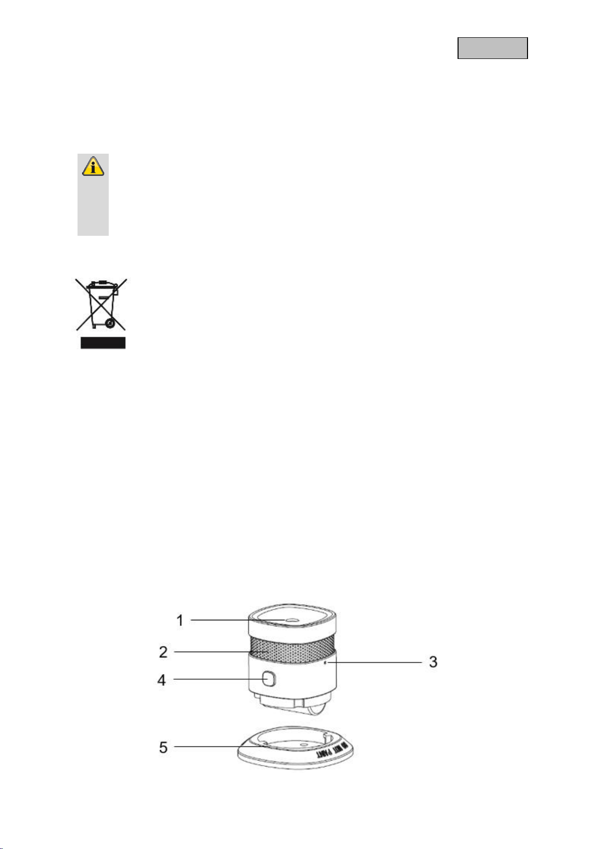
3.2. Device features........................................................................................................................ 6
3.3. Funktionsprinzip....................................................................................................................... 7
3.4. Performance Features............................................................................................................. 7
3.5. Use in systems of different manufacturers.............................................................................. 7
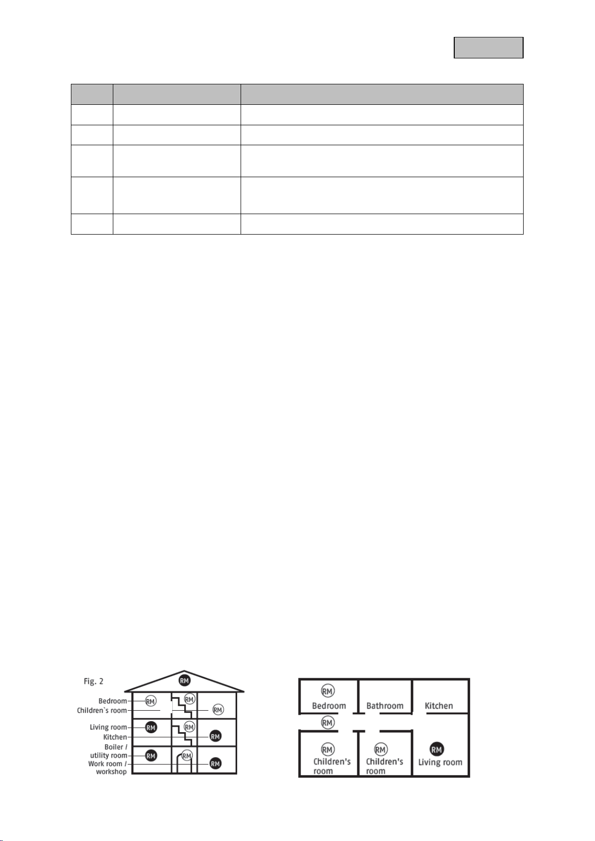
4. Selecting location ............................................................................................................................. 7
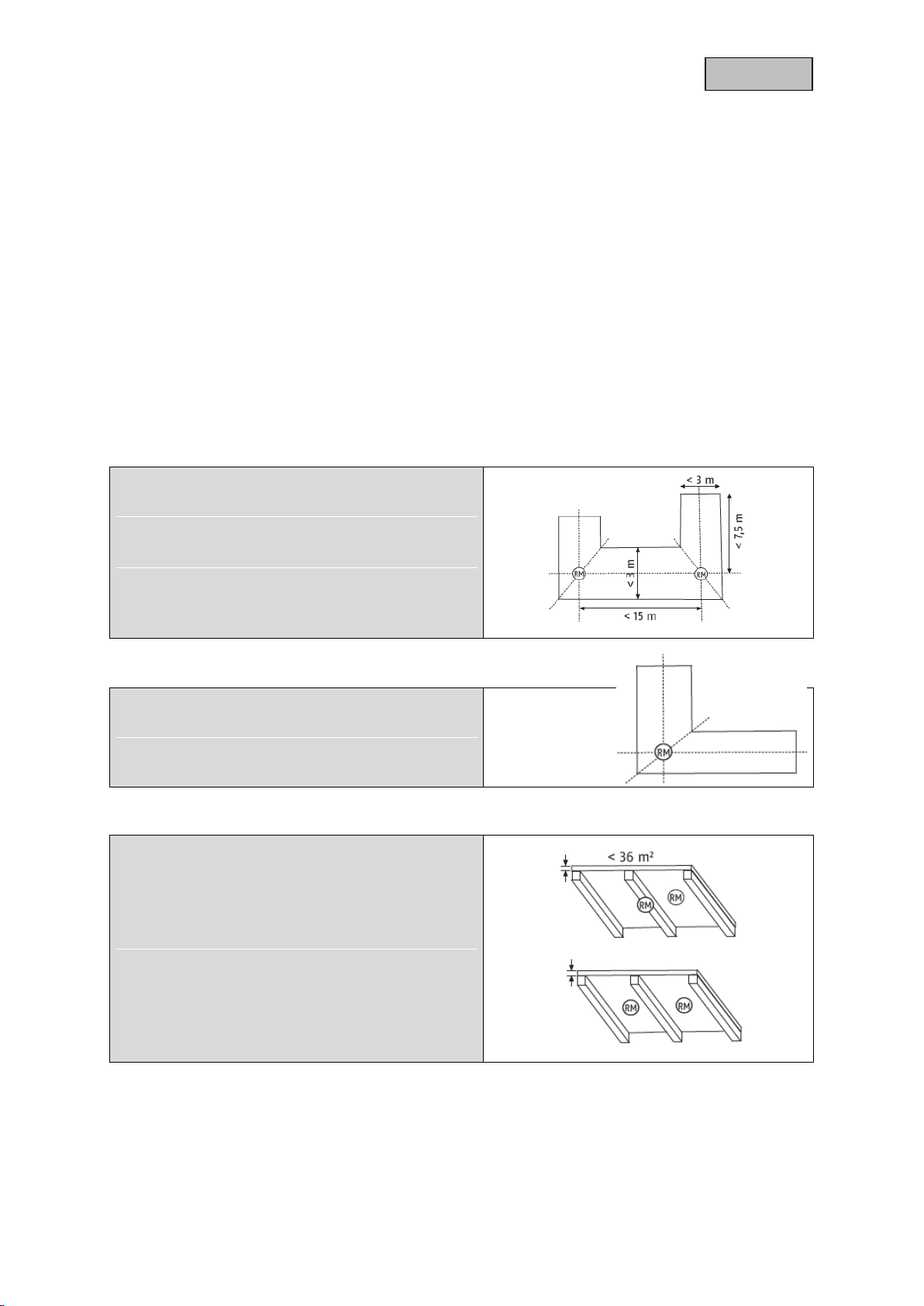
4.1. Special installation cases ........................................................................................................ 8
Where smoke alarm devices should not be installed....................................................................... 9
4.2. Normal state .......................................................................................................................... 10
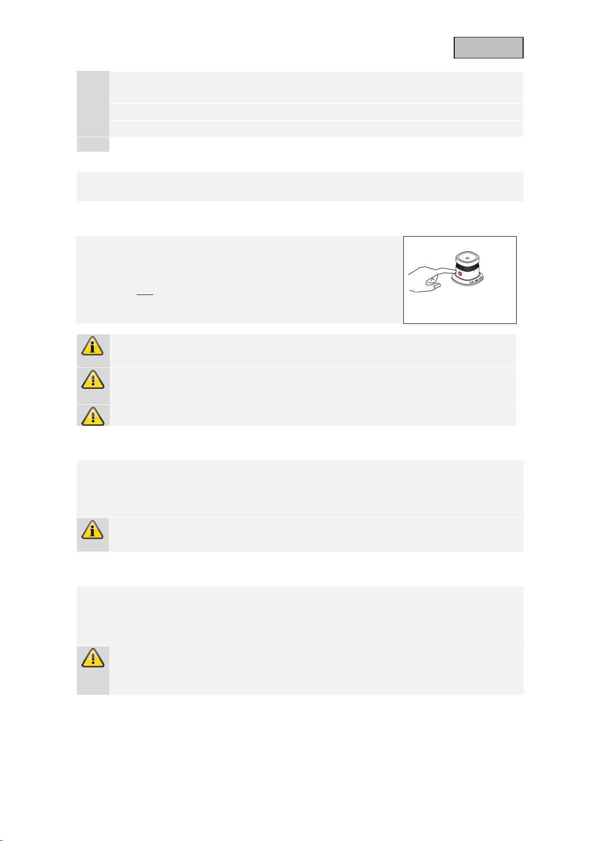
4.3. Testing the device electronics............................................................................................... 10
4.4. Weak batteries....................................................................................................................... 10
4.5. Self-test with automatic error message................................................................................. 10
4.6. Alarm state: Smoke ............................................................................................................... 11
4.7. Alarm muting function (hush mode)....................................................................................... 11
5. Overview of functions..................................................................................................................... 11
5.1. Inclusion / Add Device........................................................................................................... 11
5.2. Mounting & Installation .......................................................................................................... 12
5.3. Exclusion / Remove device ................................................................................................... 13
5.4. Reset (Factory-Reset) ........................................................................................................... 14
6. Advanced Z-Wave Parameter........................................................................................................ 14
6.1. Association Group Information .............................................................................................. 14
6.2. Supported Command Classes............................................................................................... 15
7. Technical Specifications................................................................................................................. 15

3
English
1. Introduction
Dear customer,
We are pleased that you have chosen our product and thank you for your trust! You
made a good choice.
This Magnetic contact (hereinafter referred to as the "device") has been developed and
manufactured with the utmost care. Please read these operating instructions
completely and observe all operating and safety instructions, as this ensures the best
possible handling of the device. This document is an installation and maintenance
manual.
All contained company names and product designations are trademarks of the
respective owners. All rights reserved.
If you have any questions, please contact your specialist installer or specialist trade
partner!
1.1. Declaration of Conformity
ABUS Security-Center hereby declares that the enclosed product comply with
the requirements of the following directives
RED Directive (2014/53/EU), EMC Directive (2014/30/EU), Low Voltage Directive
(2014/35/EU) and RoHS Directive (2011/65/EU). The full EU Declaration of
Conformity text can be found at:
www.abus.com/product/SHRM10000
It can also be obtained at the following adress:
ABUS Security-Center GmbH & Co. KG,
Linker Kreuthweg 5, 86444 Affing, GERMANY
1.2. Declaration of Service
This smoke detector has been tested and certified as a construction product in
accordance with EU 305/2011. Production is monitored by regular and independent
controls to ensure that legal and normative requirements are maintained.
You can find the declaration of performance SHRM10000#2018 under
www.abus.com/ger/Service/Leistungserklaerungen
1.3. Disclaimer of Liability
These operating instructions have been prepared with the greatest care. Should you
nevertheless notice omissions or inaccuracies, please inform us in writing at the above
address.
Your rights are limited to the repair or replacement of this product as delivered. ABUS
Security Center assumes no liability for any special, incidental or consequential
damages, including but not limited to loss of revenue, loss of profit, restrictions in the
use of the software, loss or recovery of data, costs for replacement equipment,
downtime, property damage and claims of third parties, as a result ofand in connection

4
English
with the use of the software.a. warranty, contractual, legal or claims for damages
notwithstanding other limited or implied warranty provisions or in the event that the
limited warranty does not apply, the scope of liability of ABUSSecurity Center is limited
to the purchase price of the product.
The contents of this manual are subject to change without notice.
© ABUS Security-Center GmbH & Co. KG, 09/2018
2. Important Safety Informations
2.1. Intended Use
Only use the device for the purpose for which it was built and designed. Any other use
is considered unintended.
All guarantee claims are invalid in the event of damage caused by non-
compliance with this safety information. We cannot be held liable for resulting
damage.
2.2. Unboxing
Handle the device with extreme care when unpacking it.
Packaging and packaging aids can be reused and, as far as possible, should be sent
for recycling.
If the original packaging has been damaged, inspect the device first. If the
device shows signs of damage, return it in the original packaging and inform
the delivery service.
2.3. Installation location / operating environment
Do not place any heavy objects on the device.The device is only designed for
operation in spaces with appropriate temperatures or humidity (e.g. bathrooms), or
excessive accumulation of dust. Please refer to the individual devices' technical data
for more detailed information. Ensure that: adequate ventilation is always guaranteed;
no direct sources of heat can affect the device; interior devices are not exposed to
direct sunlight or strong artificial light; the device is not in the immediate vicinity of
magnetic fields (e.g. loudspeakers); no naked flames (e.g. lit candles) are placed on
or next to the device; sprayed or dripping water is prevented from coming into contact
with interior devices and caustic fluids are avoided; the device is not operated in the
vicinity of water, in particular, the device should never be submerged (do not place
objects containing fluids, e.g. vases or drinks, on or near the device); no foreign bodies
penetrate the device; the device is not exposed to wide temperature variations, as
otherwise there may be condensation from humidity causing electrical short circuits;
the device is not exposed to excessive shock or vibration.
2.4. Children
Keep electrical devices out of reach of children. Never allow children to use electrical
devices unsupervised. Children may not always properly identify possible hazards.
Small parts may be fatal if swallowed. Keep packaging film away from children. There
is a risk of suffocation. This device is not intended for children. If usedincorrectly, parts
under spring tension may fly out and cause injury to children (e.g. to eyes).

5
English
2.5. Information on handling batteries
- Make sure that batteries are kept away from small children. Children may put
batteries in their mouths and swallow them. This can cause serious harm to their
health. If this happens, consult a doctor immediately.
- Do not charge normal batteries, heat them up or throw them into naked flames
(they may explode).
- The battery must not be directly exposed to heat or sunlight, and must not be
stored in a place with a very high temperature.
- The battery must not come into contact with water.
- The battery must not be dismantled, pierced or otherwise damaged.
- The battery contacts must not be short-circuited.
- Change low batteries in good time.
- Always change all the batteries at the same time and use batteries of the same
type.
- Leaky or damaged batteries can cause chemical burns on contact with the skin.
In this case, wear protective gloves. Clean the battery compartment with a dry
cloth.
2.6. Important information on battery disposal
Batteries with this label do not contain harmful substances such as
cadmium, lead and mercury. However, used batteries must not be
disposed of along with household waste in accordance with the battery
directive. To protect natural resources and promote the recycling of
materials, separate the batteries from other waste and deposit them at a
local recycling center. An additional label with the chemical symbols for
Hg, Cd or Pb means that the batteries contain quantities of mercury, cadmium or lead
which exceed the restrictions set by the EU Directive 2006/66/EG. If batteries are not
disposed of properly, these substances can cause harm to human health or the
environment
2.7. Cleaning
In accordance with the German application standard DIN 14676, the functionality of
each installed smoke detector must be regularlychecked and ensured by maintenance
measures.
This includes an inspection at least once every 12 ± 3 months including maintenance
and functional testing of the warning signals.
The results and measures must be documented accordingly.
- Dusty detectors must be cleaned. Dust deposits in the air slots of the detector
can be sucked off or blown out.
- If necessary, the dust can be removed with a brush.
- The surface can be cleaned with a cloth slightly moistened with soapy water.
- Make sure that no water gets inside the unit! Do not clean the appliance in the
dishwasher!

6
English
- Do not use sharp, pointed, abrasive, caustic cleaning agents, chemicals or hard
brushes!
Warning
The electronic components of every smoke detector are subject to ageing
processes. In addition, insect screens and smoke measuring chambers
inevitably become dirty over time.
In order to be able to guarantee the full function of every smoke alarm device,
it must be replaced no later than 10 years after commissioning!
2.8 Information on device disposal
3 Important: The EU Directive 2012/19/EU regulates the proper
return, treatment and recycling of used electronic devices. This symbol
means that in the interest of environmental protection the device must be
disposed of separately from household or industrial waste at the end of
its service life in accordance with applicable local legal guidelines.
Disposing of used devices can be done at official recycling centers in your
country. Obey local regulations when disposing of material. Further details on
returns (also for non-European countries) can be obtained at your local authority.
Separate collection and recycling saves natural resources and ensures that all the
provisions for protecting health and environment are observed when recycling the
product.
3. Product introduction
3.1. Scope of delivery
- ABUS Z-Wave Smoke detector
- Quickguide & Safety Instructions
- Installation material
3.2. Device features

7
English
Nr
Label
Comment
1
Sound outlet opening
2
Smoke inlet opening
3
Network button
For inclusion / exclusion of the detector in a Z-Wave
gateway, factory reset and tamper alarm
4
Test/hush Button
Control Light (LED)
The control light is located under the Test/hush button
and shines through it
5
Detector base
With mounting holes
3.3. Funktionsprinzip
The SHRM10000 was developed for use in home automation systems that use the Z-
Wave wireless standard. The detector alarms loudly thanks to the integrated siren (>
85dB). When the battery level is low, the detector automatically gives feedback to the
gateway.
In conjunction with configurable scenes, smart functions can also be initiated in
addition to the alarm, e.g. smoke detector triggers, front door unlocks for emergency
services.
3.4. Performance Features
The ABUS Z-Wave SHRM10000...:
- …is a battery-operated radio smoke detector
- …is Z-Wave PLUS compatible & certified
- …supports the Z-Wave S2 Standard (Security 2)
- …reliably detects smoke development
- …alerts in case of fire via loudspeaker and alarm message to the gateway
- ... has a battery-empty warning function
- …was developed for indoor installation
3.5. Use in systems of different manufacturers
Communication is via the Z-Wave EU frequency (868.42 Mhz). You can integrate the
device into any Z-Wave network with a certified Z-Wave gateway, regardless of
manufacturer. All non-battery powered nodes in the networkact as repeater to increase
the durability of the network.
4. Selecting location
c
c
c

8
English
Smoke alarm devices are to be used as the bare minimum equipment in all
bedrooms, children's rooms and hallways which act as escape routes, and are to be
installed in each case in the middle of the room, on the ceiling only (do not install on
a wall) (Fig. 2). Select the highest installation location with a minimum distance of
50 cm to surrounding walls, furniture and lamps. In the case of sloping ceilings with
an angle of over 20°, detectors should be installed 0.5 - 1 m away from the highest
point. Configuration is optimal when devices are located in all other rooms as well as
staircases. In washrooms (bathrooms, lavatories etc.), a smoke alarm device is
generally not necessary because the risk of fire is low.
Please note the graphics in this manual and the detailed information available in the
EN14676 standard “Smoke alarm devices for use in residential buildings, apartments
and rooms with similar purposes –Installation, use and maintenance”.
4.1. Special installation cases
Installation in a hallway with a width of < 3 m
Maximum distance from the front walls:
7.5 m
Maximum distance between detectors:
15 m
Installation on the mitre line between
intersecting crossings, T-junctions and
corner areas
Installation in an L-shaped room
Total area of < 60m²: installation on the
mitre line
Total area of > 60m²: each side is
treated as a separate room
Ceiling beams
In the case of ceiling beams measuring
> 0.2 m and a total area of < 36 m²,
detectors should be installed in the
centre of the room either on a beam or
ceiling panel.
In the case of ceiling beams measuring
> 0.2 m and a total area of > 36 m²,
detectors should be installed in the
centre of each ceiling panel and not on
the beams.

9
English
Mezzanines and landings
In the case of
mezzanines and
landings with a length
and width of > 2 m
and a total area of >
16 m², an additional
smoke alarm should
be installed in the
centre of the surface
area.
Sloped ceilings
There are no special
requirements for
ceilings sloped at an
angle of < 20°.
In the case of ceilings
sloped at an angle of
> 20°, detectors
should be installed
0.5–1 m away from
the highest point.
Partially sloped ceilings
The instructions for
fully sloped ceilings
apply for partially
sloped ceilings with a
horizontal ceiling
surface measuring <
1 m in width.
In the case of partially
sloped ceilings with a
horizontal ceiling
surface measuring >
1 m, detectors should
be installed in the
centre of the
horizontal surface.
Where smoke alarm devices should not be installed
Outside (use only in closed rooms)
In an mounting height > 6 meters

10
English
In rooms in which the alarm could be triggered by disturbance variables
(steam, condensation, “normal” smoke, vapour, dust, dirt or grease)
Next to an air duct or similar ventilation opening (draughts)
In areas in which the temperature can fall below 0°C or rise to over 40°C
4.2. Normal state
In the normal state, the red control LED under the housing cover flashes once
every 53 seconds and signals that the detector is ready for operation.
4.3. Testing the device electronics
Regularly check the functionality of the smoke alarm device
by pressing the Test button. The warning tone signals and
the red “ALARM” LED flashes quickly
This does not indicate that smoke is present in the air in the
room; it is a confirmation that the smoke alarm device is
functioning properly.
Test the functionality of the detector after installation without fail. A regular
test is also recommended.
Keep the device at arm's length to protect your hearing.
To carry out a test, press the Test button shortly.
4.4. Weak batteries
If the detector's battery charge falls below a certain value, the detector signals this
with a Red LED Flash and an acoustic warning tone (every 53 seconds). If this
warning signal sounds, the detector batteries must be immediately replaced with
new batteries.
From the time of the first battery warning signal, the detector is still operable
and completely functional for at least 7 more days.
4.5. Self-test with automatic error message
The smoke alarm device periodically runs a self-test.
If the trigger sensitivity of the detector falls below the required minimum threshold
(e.g. as a result of excess contamination of the smoke measurement chamber),
the detector beeps twice and the red LED flashes every 53 seconds.
If the error message does not clear after the detector has been cleaned, the
detector must be replaced immediately (see “Care and maintenance”
chapter).

11
English
4.6. Alarm state: Smoke
If smoke is detected, a loud, pulsing alarm tone sounds and the red LED flashes
at the same time at short intervals. In this case, proceed as described in the
“Behaviour in case of alarm” chapter.
4.7. Alarm muting function (hush mode)
If the detector is in the alarm state, the acoustic alarm can
be deactivated for 10 minutes by pressing the Test button.
If the muting function is active, the red LED flashes every
10 seconds.
If smoke is still detected in the smoke measurement
chamber after the 10-minute muting period, the acoustic
alarm will sound again.
5. Overview of functions
5.1. Inclusion / Add Device
A
Slide the base unit from the mounting plate
and remove the safety strip from the battery
compartment
B
Click the + (Add) button in your Z-Wave App
and follow the further instructions

12
English
C
Press the Network-button 3 times within 1.5
seconds and the Status-LED on the base unit
front will flash 3 times
The App will show if the Add device process
was successful and the Status-LED will turn
off
Repeat the inclusion process from step B if it
was not successful.
5.2. Mounting & Installation
A
Fasten the mounting plate to the ceiling with
the screws (recommended)
Alternative: Loosen the cover of the double-
sided adhesive and glue the mounting plate
to the ceiling.
Note:
When marking the drill holes, make sure that
there are no electrical lines/cables, pipes or
other important installation components
behind the installation site!
Failure to observe the instructions on site
selection and installation may result in injury,
e.g. due to falling smoke alarm detectors
B
Mount the device on the mounting bracket by
turning it clockwise to lock it into place

13
English
C
Check the functionality of the smoke alarm
device by pressing the Test button. The
warning tone signals and the red “ALARM”
LED flashes quickly
This does not indicate that smoke is present
in the air in the room; it is a confirmation that
the smoke alarm device is functioning
properly.
5.3. Exclusion / Remove device
A
Click the - (Remove) button in your Z-Wave
App and follow the further instructions
B
Press the Network-button 3 times within 1.5
seconds and the Status-LED on the base unit
front will flash 3 times
The App will show if the Remove device
process was successful and the Status-LED
on device will flash 6 times
Repeat the exclusion process from step A if it
was not successful.

14
English
5.4. Reset (Factory-Reset)
1. Remove the battery
2. Press the Network button and keep it
pressed while inserting the battery again.
3. Device will restore factory settings
Note:
1, This procedure should only be used if the
primary gateway is not capable of acting.
2, If the multi-sensor is set to the factory
setting, the status is set to "not included", the
association settings and possible
configurations are reset to default.
5.5 Battery change
1. Turn the device anticlockwise and
remove it from the mounting bracket and
remove the old battery
2. Insert a new battery, ensure that the
polarity is correct
3. Test the smoke alarm device. To do so,
press and release the test button. The
alarm will sound loud short beeps
indicating that the smoke detector works
normally
Turn the detector back onto the bracket
6. Advanced Z-Wave Parameter
6.1. Association Group Information
Z-Wave devices can control other devices directly. This direct control is called in Z-
Wave association. For this purpose, the device ID of the device to be controlled must
be stored in the controlling devices. This is done in so-called association groups. An
association group is always linked to an event in the controlling device (pressing a key
or triggering a sensor). When this event occurs, a control command - usually a BASIC
SET - is sent to all devices stored in an association group.
The smoke detector supports the following association groups:

15
English
Group
Number
Maximum
Devices
Transmitted Content
Group 1
0x05
Association group 1: Lifeline association group Include
command classes: Battery report, Notification report, and
Device Reset Locally notification, Binary report.
Group 2
0x05
Association group 2: Root Device group(Binary Sensor)
Binary Sensor Command Class: Compatible with 300
series 1-Binary Sensor reports status of smoke or no
smoke via Lifeline. 2-When the sensor detects
status change between smoke and no smoke, the device
will be triggered.
Group 3
0x05
Association group 3: Root Device group(Notification) 1-
Notification reports reports status of detect smoke or no
smoke via Lifeline. 2-When the sensor detects status
change between smoke and no smoke, the device will be
triggered.
6.2. Supported Command Classes
1 Z-Wave plus Info Version 2
2 Notification Version 8
3 Association Version 2
4 Association Group Info Version 1
5 Transport Service Version 2
6 Version Version 3
7 Manufacturer Specific Version 2
8 Device Reset Locally Version 1
9 Powerlevel Version 1
10 Battery Version 1
11 Security 2 Version 1
12 Supervision Version 1
13 Wake Up Version 2
7. Technical Specifications
Parameters
Unit
SHRM10000
Dimensions
mm
60 x 60 x 49,2
Weight
g
66
Operating Temperature
°C
0 –40
Max. Humidity
%
95
IP Class
20
Radio frequency
MHz
868,42 (Z-Wave PLUS, Europe)
Material
ABS, poliert
Transmission power
db
< 4,5
Power supply
3 V DC
Battery type
CR123 (CR17335) EVE (1500mA)

16
English
Power consumption standby
mA
0,01
Power consumption trigger
mA
90
Battery-life
5 Jahre (1 trigger per month + 1 heartbeat
per day + 1 active report per day)
Range (open field)
m
100
Range (building)
m
20, related to material of walls
Tamper protection
No
Firmware updateable
No
Support Z-Wave Beaming
No
SmartStart supported
No
Z-Wave Network Security
Yes
Z-Wave AES-128 Security
Yes
Z-Wave Plus
Yes
Security S2 Classes
Yes
Z-Wave Chip Generation
500
Z-Wave Sensor-Typ
Open/Closed (Binary)
Zwave library type
Routing Slave
Device Type / Role type
Notification sensor /
Reporting sleeping slave
Other manuals for SHRM10000
1
Table of contents
Other Abus Smoke Alarm manuals