ACME LED-BL4B User manual

Stage Blinder B4
LED-BL4B
User Manual
Please read the user manual before use

1B
Contents
1. Safety Instructions……………………………………………………….2
2. Technical Specifications…………………………………………………5
3. Installation…………………………………………………………………6
4. How to set the unit………………………………………………….…….6
4.1 Rear Panel…………………………………………………………………6
4.2 Main Function…………………………………………………………….8

2B
5. How To Control The Unit………………………………………………..12
6. DMX Channel Mode……………………………………………………….13
7. DMX512 Connections…………………………………………………....15
8. Troubleshooting……………………………………………………………16
9. Fixture Cleaning…………………………………………………………….17
1. Safety Instructions
WARNING
Please keep this User Manual for future consultation. If you sell the fixture to another user,
be sure that they also receive this instruction booklet.
Please read the instructions carefully which includes important
information about the installation, operation and maintenance.

3B
Please unpack and check carefully there is no transportation damage before using the
fixture.
Please disconnect main power before servicing and maintenance.
The unit must be installed in a location with adequate ventilation, at least 50cm from
adjacent surfaces. Be sure that no ventilation slots are blocked.
The maximum ambient temperature is Ta: 40℃. DO NOT operate it where the
temperature is higher than this.
DO NOT connect the device to any dimmer pack.
The housing must be replaced if they are visibly damaged.
Unit surface temperature may reach up to 85℃. Don’t touch the housing bare-hand
during its operation. Turn off the power and allow about 15 minutes for the unit to cool
down before replacing or serving.
There are no user serviceable parts inside the fixture. Do not open the housing or attempt
any repairs by yourself. In the unlikely event your fixture may require service, please
contact your nearest dealer.
In the event of serious operating problem, stop using the fixture immediately. Never try to
repair the fixture by yourself. Repairs carried out by unskilled people can lead to damage
or malfunction. Please contact the nearest authorized technical assistance center. Always
use the same type spare parts.
It’s important to ground the yellow/green conductor to earth in order to avoid
electric shock.
DO NOT touch any wire during operation and there might be a hazard of electric shock.
DO NOT expose the fixture to rain or moisture, in order too prevent or reduce
the risk of electrical shock or fire.
Do not look directly at the LED light beam while the fixture is on.

4B
2. Technical Specifications
DMX 1/2/4/5 channels switchable.
Dimming, Strobe, Sound Active and easy controller CA-8
Two operation modes: DMX, Master/Slave.
Ideal for discotheques, clubs, bars, parties, Mobile DJs, etc.
Input Voltage: AC 100V~240V 50/60Hz
Total Power consumption: 400W
Fuse: T6.3A
LED: 4 x 65W LED
Dimension: 868X141X306mm
Weight: 7.5Kgs
For AC 220-240V power supply, the maximum fixtures that can be connected on
one power cable is 4(including the first fixture) ;
For AC 100~120V power supply, the maximum fixtures that can be connected on
one power cable is 2 (including the first fixture).

5B
3. Installation
The unit should be mounted via its screw holes on the bracket. Always ensure that the
unit is firmly fixed to avoid vibration and slipping while operating. Always ensure that the
structure to which you are attaching the unit is secure and is able to support a weight of 10
times of the unit’s weight. Also always use a safety cable that can hold 12 times of the weight
of the unit when installing the fixture.
The equipment must be fixed by professionals. And it must be fixed at a place where is out
of the touch of people and has no one pass by or under it.
4. How to set the unit
4.1 Rear Panel

6B
○
1 Mains input/output:
Connect to supply mains power, and connect to supply mains power for the next unit.
○
2 Fuse holder: T6.3A
○
3 CA-8 Connector: Connect with easy controller CA-8
○
4Sound Active Port: Receive Sound active signal
○
5DMX input/output:
For DMX512 link, use 3-pin XLR plug cable to input DMX signal, and to link the next unit.
○
6Button:
MENU
To select the programming functions
DOWN
To go backward in the selected functions
UP
To go forward in the selected functions
ENTER
To confirm the selected functions
○
7 LED indicator:
Signal
Flash
Signal input present
Master
On
Master

7B
Slave
On
Slave
Sound
Flash
Sound active signal input
○
8Display: Show the various menus and the selected functions
4.2 Main Function
To select any functions, press MENU button until the required one is shown on the display.
Select the function by ENTER button. Use DOWN and UP button to change the mode. Once
the required mode has been selected, press ENTER button to setup or it will return to the
main functions without any change after idling 8 seconds automatically. Back to the functions
without any change press MENU button. The main functions are shown below:
DMX 512 Address
Select the , press the ENTER button and the display will blink. Use the DOWN and UP
button to change the DMX 512 address(001-512). Once the address has been selected,
press the ENTER button to setup or exit menu mode without any change after 8 seconds

8B
automatically. Back to the previous functions without any change press the MENU button.
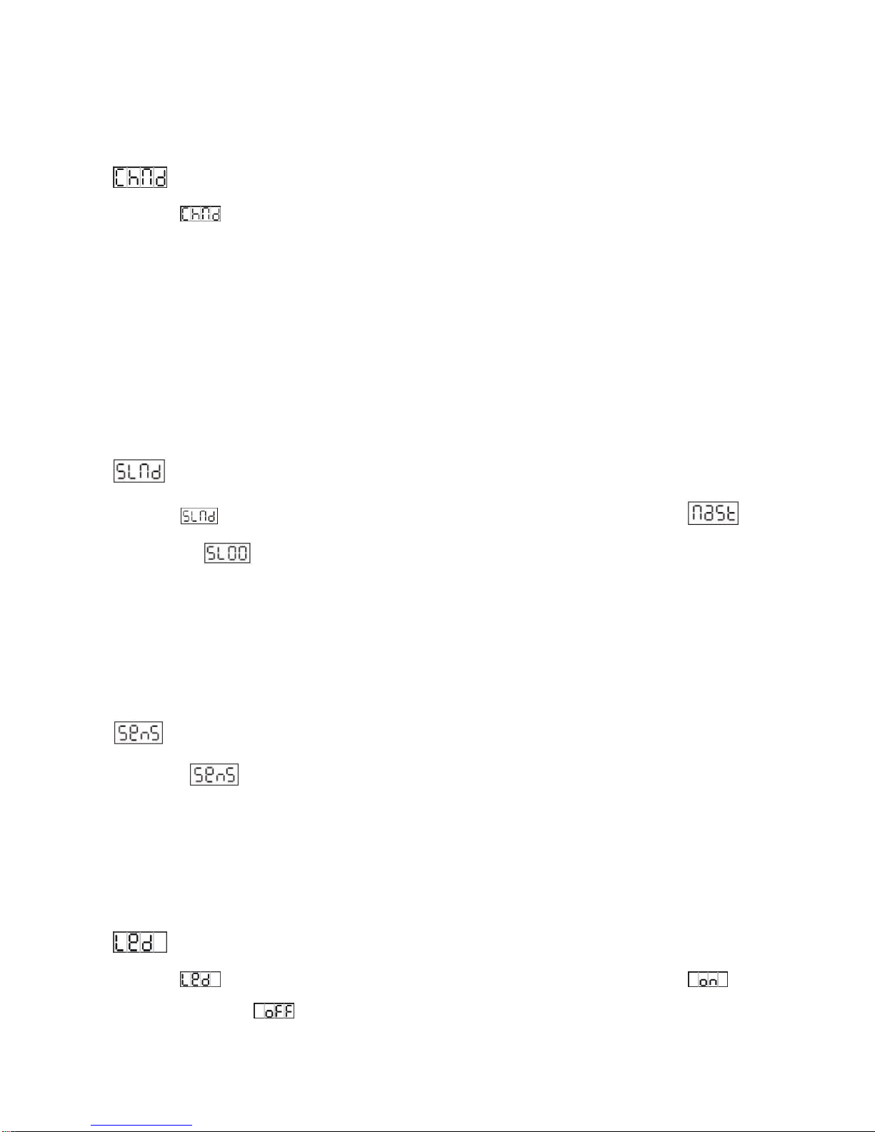
Channel Mode
Select the , press the ENTER button. Use the DOWN and UP button to select the
channel mode (1/ 2/4/5CH)( 1 channel mode control bright of 4 LED, 2 channel mode means
1st channel mode control bright of 4 LED , 2nd channel control effect of 4 LED, 4 channel
mode control bright of 4 LED by separate, 5 channel mode control bright of 4 LED by
separate, and 5th channel control effect of 4 LED ). Once selected, press the ENTER button to
setup or exit menu mode without any change after 8 seconds automatically. To go back to the
functions without any change,pls press the MENU button
Master/Slave Mode
Select the, press the ENTER button. Use the DOWN and UP button to select
(Master) 、(Slave)(Note: Each 2 units as one group, such as MAST, SL01 as one
group, SL00, SL01 as another group.), after selected, press the ENTER button. Or exit menu
mode without any change after 8 seconds automatically. To go back to the functions without
any change press the MENU button.
Sensitivity
Select the ,press the ENTER button. Use the DOWN and UP button to select the
sensitivity (000-100).Once selected, press the ENTER button to setup or exit menu mode
without any change after 8 seconds automatically. To go back to the functions without any
change press the MENU button
LED display
Select the , press the ENTER button. Use the DOWN and UP button to select
(LED display on) or (LED display off, after 30 sec. without any move, display will off

9B
again). Once selected, press the ENTER button to setup or exit menu mode without any
change after 8 seconds automatically. Back to the functions without any change press the
MENU button again.
Display direction
Select the , press the ENTER button. Use the DOWN and UP button to select
(positive display) or (reverse display). Once selected, press the ENTER button to
setup or exit menu mode without any change after 8 seconds automatically. Back to the
functions without any change press the MENU button again.
Blackout Mode
Select the , press the ENTER button. Use the DOWN and UP button to select
(when without DMX signal, the output will be “0”) or (when without DMX signal, the
master will run the built-in CHASE ,and the slave will keep the same running status ). Once
selected, press the ENTER button to setup or exit menu mode without any change after 8
seconds automatically. Back to the functions without any change press the MENU button
again.
Temperature Display
Select the , press ENTER button and the display will show the temperature of each
unit ,. To go back to the functions press the MENU button.
Firmware version
Select the , press ENTER button and the display will show the version of software of the
unit. To go back to the functions press the MENU button.

10B
5. How To Control The Unit
5.1 Two ways to operate the unit:
1. By master/slave
2. By DMX controller
No need to turn the unit off when you change the DMX address, as new DMX address setting
will be affected at once. Turn on the unit, under the DMX signal , the LED will display the
saved channel address(001-512); If without DMX signal,
The master will show SH00-SH12(Chase Mode )、STRO(Strobe Mode) or DIM (Dimming
Mode ),the slave will show SL00-SL01; If there is something wrong in the temperature
checkout console or the temperature over high/low, the LED will display TERR, and the unit
will flash (light on /light off) in a very low brightness continually. The master/slave on line can
use easy controller CA-8 to control the master to change the mode (Sound active Chase、
Chase automatically、Strobe and Dimming )
5.2 Easy controller (by CA-8)
The easy remote control is used only in master/slave mode. By connecting to the first master
unit, you will find that the remote controller on the first unit will control all the other units for
Standby, Function and Mode selection
6.
DMX512
Channel
Mode
STAND BY
Blackout the unit (the LED indicator will light on/off
accordingly)
FUNCTION
1. Short Enter can be shifted Synchronous Strobe/Random
Strobe/ sound Strobe;( Mode1)
2. Change the SHOW effect (0-12);(Mode2)
3. Change the lightness;( Mode3)
MODE
1,Run the SHOW by sound (LED indicator off);( default
mode);
2,Run the SHOW by auto. (LED indicator flash);
3,Dimming(LED indicator on);

11B
Channel mode:

12B
7. DMX512 Connections
Mode connection:
1. Connect the fixture together in a “daisy chain” by XLR plug cable from the output of the
fixture to the input of the next fixture. The cable cannot be branched or split to a “Y”
cable. Inadequate or damaged cables, soldered joints or corroded connectors can easily
distort the signal and shut down the system
2. The DMX output and input connectors are pass-through to maintain the DMX circuit

13B
when one of the units’ power is disconnected.
3. At last fixture, the DMX cable has to be terminated with a terminator to reduce signal
errors. Solder a 120-ohm 1/4W resistor between pin 2(DMX-) and pin 3(DMX+) into a
3-pin XLR-plug and plug it in the DMX-output of the last fixture.
4. Each lighting fixture needs to have an address set to receive the data sent by the controller.
The address number is between 0-511 (usually 0 & 1 are equal to 1).
5. 3 pin XLR connectors:.
3 pin XLR: Pin 1: GND, Pin 2: Negative signal (-), Pin 3: Positive signal (+)
8. Troubleshooting
Following are a few common problems that may occur during operation. Here are some
suggestions for easy troubleshooting:
A. The fixture does not work, no light
1. Check the connection of power and main fuse.
2. Measure the mains voltage on the main connector.
B. Not responding to DMX controller
1. DMX LED should be on. If not, check DMX connectors, cables to see if link properly.
2. If the DMX LED is on and no response to the channel, check the address settings and DMX
polarity.
3. If you have intermittent DMX signal problems, check the pins on connectors or on PCB of
the fixture or the previous one.
4. Try to use another DMX controller.
5. Check if the DMX cables run near or run alongside to high voltage cables that may cause
damage or interference to DMX interface circuit.
9. Fixture Cleaning
The cleaning of internal must be carried out periodically to optimize light output. Cleaning

14B
frequency depends on the environment in which the fixture operates: damp, smoky or
particularly dirty surrounding can cause greater accumulation of dirt on the fixture’s optics.
Clean with soft cloth using normal glass cleaning fluid.
Always dry the parts carefully.
Clean the external optics at least every 20 days. Clean the internal optics at least every
30/60 days.
Fresnel lens:
Clean the lens with neutral soap and water, and then dry it with soft cloth. Be aware that
alcohol or other detergent could cause damage to lens. Please note the lens would be burnt
yellow or cracked after three-month use of average 8 hours per day, which can reduce the
output in some degree. The lens is consumable with a warranty of three months only. Please
change with genuinely new lens when necessary.
Declaration of Conformity
We declare that our products (lighting equipments) comply with the
following specification and bears CE mark in accordance with the
provision of the Electromagnetic Compatibility (EMC) Directive
2004/108/EC.
EN55103-1: 2009 ; EN55103-2: 2009;
EN61000-3-2: 2006 + A1:2009 + A2:2009; EN61000-3-3: 2008.
&
Harmonized Standard
EN 60598-1:2008 + All:2009; EN 60598-2-17:1989 + A2:1991;
EN 62471:2008; EN 62493: 2010
Safety of household and similar electrical appliances
Part 1: General requirements

15B

16B
Innovation, Quality, Performance
Table of contents
Other ACME Dj Equipment manuals

ACME
ACME ENERGY SPOT XA-400 SPOT User manual

ACME
ACME Genesis move 25R User manual

ACME
ACME Color Fusion CF-805 User manual

ACME
ACME LP-TS200 CW User manual

ACME
ACME Ellipsoidal User manual

ACME
ACME LED-RC8 User manual

ACME
ACME LED-MB50 User manual

ACME
ACME MACE User manual

ACME
ACME LED-MS150 User manual

ACME
ACME LED-MTX36 HEX User manual

ACME
ACME Festival LED-787 User manual

ACME
ACME IU-01 User manual

ACME
ACME CP-21TC User manual

ACME
ACME MH-275R User manual

ACME
ACME E-40D TC DXX User manual

ACME
ACME PAGEANT 300ZR II User manual

ACME
ACME SAM-50 User manual

ACME
ACME LED-BL8 User manual

ACME
ACME Color Spot User manual

ACME
ACME RAYZOR HYBRID XA-100 BSW User manual