ACME Elf Laser User manual

Elf Laser
UserGuide
Professional Entertainment Technology
1-
TABLE OF CONTENTS
1. Safety Instruction
2. Technical Specification
3. How To Set The Unit
4. How To Control The Unit
5. Troubleshooting
6. Fixture Cleaning

2-
1. Safety Instruction
WARNING
yPlease keep this User Guide for future consultation. If you sell the unit to another user, be
sure that they also receive this instruction booklet.
yUnpack and check carefully there is no transportation damage before using the unit.
yBefore operating, ensure that the voltage and frequency of power supply match the power
requirements of the unit.
yIt’s important to ground the yellow/green conductor to earth in order to avoid electric
shock.
yThe unit is for indoor use only. Use only in a dry location.
yThe unit must be installed in a location with adequate ventilation, at least 50cm from
adjacent surfaces. Be sure that no ventilation slots are blocked.
yDisconnect main power before replacement or servicing.
yMake sure there is no flammable materials close to the unit while operating as it is fire
hazard.
yUse safety cable when fixes this unit.
yMaximum ambient temperature is Ta: 40℃. Don’t operate it where the temperature is
higher than this.
yIn the event of serious operating problem, stop using the unit immediately. Never try to
repair the unit by yourself. Repairs carried out by unskilled people can lead to damage or
malfunction. Please contact the nearest authorized technical assistance center. Always
use the same type spare parts.
yDo not touch any wire during operation as high voltage might be causing electric shock.
Warning
yTo prevent or reduce the risk of electrical shock or fire, do not expose the unit to rain or
moisture.
yDo not open the unit within five minutes after switching off.
yThe housing, the lenses, or the ultraviolet filter must be replaced if they are visibly
damaged.
Please read carefully the instruction, which includes important information
about the installation, usage and maintenance.
3-
Caution
There are no user serviceable parts inside the unit. Do not open the housing or attempt
any repairs yourself. In the unlikely event your unit may require service, please contact
your nearest dealer.
Installation
The unit should be mounted via its screw holes on the bracket. Always ensure that the
unit is firmly fixed to avoid vibration and slipping while operating. Always ensure that the
structure to which you are attaching the unit is secure and is able to support a weight of 10
times of the unit’s weight. Also always use a safety cable that can hold 12 times of the
weight of the unit when installing the fixture.
The equipment must be fixed by professionals. And it must be fixed at a place where is
out of the touch of people and has no one pass by or under it.
2. Technical Specification
•4 DMX Channels:
Channel 1 = Pan
Channel 2 = Tilt
Channel 3 = Pattern
Channel 4 = Line
•Voltage: 120V/230V~50/60Hz
•Laser Power: Green 30mW
•Fuse: 1A
•Power Consumption: 21W
•Dimension: 248 x 194 x 298 mm
•Weight: 4.4 kg

4-
3. How To Set The Unit
3.1 Main Function
To select any of the given functions, press the MENU button up to when the required one is
showing on the display. Select the function by ENTER button and the display will blink. Use
DOWN and UP button to change the mode. Once the required mode has been selected,
press the ENTER button to setup or it will automatically return to the main functions without
any change after idling 8 seconds. To go back to the functions without any change press the
MENU button. The main functions are showing below:
5-
DMX 512Address Setting
Press the MENU button up to when the is showing on the display. Pressing ENTER
button and the display will blink. Use DOWN and UP button to change the DMX512 address.
Once the address has been selected, press the ENTER button to setup or automatically
return to the main functions without any change after 8 seconds. To go back to the functions
without any change press the MENU button again.
ShowMode
Press the MENU button up to when the is showing on the display. Pressing ENTER
button and the display will blink. Use DOWN and UP button to select the (show 1)
or (show 2) or (show 3) or (show 4) mode. Once the mode has
been selected, press the ENTER button to setup or automatically return to the main
functions without any change after 8 seconds. To go back to the functions without any
change press the MENU button again.
Show 1 mode - Fixture is placed on the floor. Tilt movement angle 210°.
Show 2 mode - Fixture is fixed under ceiling. Tilt movement angle 90°.
Show 3 mode - Fixture is placed on the speaker, The spot is always projecting
to the audience’s direction; i.e in front of the stage. Pan movement angel (left to right to
left): 160°. Tilt movement angel: 90° (60° above horizon; 30° below horizon.)
Show 4 mode - Fixture is fixed under ceiling. The spot is mainly projecting in
front of the stage. Pan movement angel (left to right to left):160°. Tilt movement angel:
90° (vertically, front 75°; back 15°)
Slave Mode
Press the MENU button up to when the is showing on the display. Pressing
ENTER button and the display will blink. Use DOWN and UP button to select the
(normal) or (2 light show) mode. Once the mode has been selected, press the
ENTER button to setup or automatically return to the main functions without any change
after 8 seconds. To go back to the functions without any change press the MENU button
again.
Sound Mode
Press the MENU button until the is showing on the display. Pressing ENTER button

6-
and the display will blink. Use DOWN and UP button to select the (sound on) or
(sound off) mode. Once the mode has been selected, press the ENTER button to
setup or automatically return to the main functions without any change after 8 seconds. To
go back to the functions without any change press the MENU button again.
Blackout Mode
Press the MENU button up to when the is showing on the display. Pressing
ENTER button and the display will blink. Use DOWN and UP button to select the
(yes blackout) or (no blackout) mode. Once the mode has been selected, press the
ENTER button to setup or automatically return to the main functions without any change
after 8 seconds. To go back to the functions without any change press the MENU button
again.
Pan Inversion
Press the MENU button up to when the is showing on the display. Pressing ENTER
button and the display will blink. Use DOWN and UP button to select the (normal)
or (pan inversion) mode. Once the mode has been selected, press the ENTER
button to setup or automatically return to the main functions without any change after 8
seconds. To go back to the functions without any change press the MENU button again.
Tilt Inversion
Press the MENU button up to when the is showing on the display. Pressing ENTER
button and the display will blink. Use DOWN and UP button to select the (normal)
or (tilt inversion) mode. Once the mode has been selected, press the ENTER
button to setup or automatically return to the main functions without any change after 8
seconds. To go back to the functions without any change press the MENU button again.
Led Display
Press the MENU button up to when the is showing on the display. Pressing
ENTER button and the display will blink. Use DOWN and UP button to select the
(Led on) or (Led off) mode. Once the mode has been selected, press the ENTER
button to setup or automatically return to the main functions without any change after 8
seconds. To go back to the functions without any change press the MENU button again.
7-
Display Inversion
It is good for you to install the unit on the floor or under ceiling. Press the MENU button up to
when the is blinking on the display. Use the ENTER button to change to the mode
(display normal), It will automatically store after 8 seconds. Or press the ENTER
button again return to the mode (display inversion). To go back to the functions
press the MENU button.
Display normal mode for the fixture putting on the floor.
Display inversion mode for the fixture fixing under ceiling.
Self-Test
Press the MENU button up to when the is blinking on the display. Pressing ENTER
button and the unit will run self-test by built-in program. To go back to the functions press the
MENU button again.
Fixture Hours
Press the MENU button up to when the is blinking on the display. Pressing ENTER
button and the display will show the number of working hours of the unit. To go back to the
functions press the MENU button again.
Software version
Press the MENU button up to when the is blinking on the display. Pressing ENTER
button and the display will show the version of software of the unit. To go back to the
functions press the MENU button again.
Reset
Press the MENU button up to when the is blinking on the display. Pressing ENTER
button and all channels of the unit will return to their standard position. To go back to the
functions without any change press the MENU button again.

8-
4. How To Control The Unit
You can operate the unit in three ways:
1. By master/slave built-in preprogram function
2. By easy controller
3. By universal DMX controller
No need to turn the unit off when you change the DMX address, as new DMX address
setting will be effected at once. Every time you turn the unit on, it will show on the
display and move all the motors to their ‘home’ position. After that the unit will be ready to
receive DMX signal or run the built in programs.
4.1 Master/Slave Built In Preprogrammed Function
By linking the units in master/slave connection, the first unit will control the other units to
give an automatic, sound activated, synchronized light show. This function is good when you
want an instant show.
2-light show
In (slave mode), means the unit works normally and means
2-light show. In order to create a great light show, you can set on the second unit to
get contrast movement to each other, even if you have two units only.
4.2 Easy Controller
The easy remote control is used only in master/slave mode. By connecting CA-8 to the 1/4”
microphone jack of the first unit, you will find that the remote control on the first unit will
control all the other units functions press the MENU button again.
4.3 DMX Controller
Use universal DMX controller to control the units, you have to set DMX address from 1 to
512 so that the units can receive DMX signal.
Press the MENU button up to when the is showing on the display. Pressing ENTER
Stand By Blackout the unit
Function 1. Continuous line
2.Hold for Incontinuous line
Show
1-4
Pattern
21
Mode Sound (LED OFF) LED Blinking LED ON
9-
button and the display will blink. Use DOWN and UP button to change the DMX512 address.
Once the address has been selected, press and keep ENTER button pressed up to when
the display stops blinking or storing automatically 8 seconds later. To go back to the
functions without any change press the MENU button again. Please refer to the following
diagram to address your DMX512 channel for the first 4 units:
4.4 DMX 512 Configuration

10-
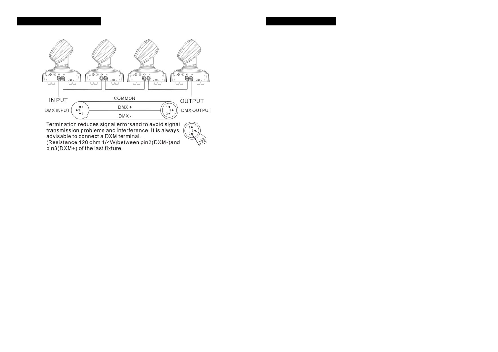
4.5 DMX512 Connection
The DMX 512 is widely used in intelligent lighting control, with a maximum of 512 channels.
1. If you using a controller with 5 pins DMX output, you need to use a 5 to 3 pin
adapter-cable.
2. At last unit, the DMX cable has to be terminated with a terminator. Solder a 120 ohm
1/4W resistor between pin 2(DMX-) and pin 3(DMX+) into a 3-pin XLR-plug and plug it
in the DMX-output of the last unit.
3. Connect the unit together in a `daisy chain` by XLR plug from the output of the unit to
the input of the next unit. The cable can not branched or split to a `Y` cable. DMX 512 is
a very high-speed signal. Inadequate or damaged cables, soldered joints or corroded
connectors can easily distort the signal and shut down the system.
4. The DMX output and input connectors are pass-through to maintain the DMX circuit,
when one of the units’ power is disconnected.
5. Each lighting unit needs to have an address set to receive the data sent by the
controller. The address number is between 0-511 (usually 0 & 1 are equal to 1).
6. The end of the DMX 512 system should be terminated to reduce signal errors.
7. 3 pin XLR connectors are more popular than 5 pin XLR.
3 pin XLR: Pin 1: GND, Pin 2: Negative signal (-), Pin 3: Positive signal (+)
5 pin XLR: Pin 1: GND, Pin 2: Negative signal (-), Pin 3: Positive signal (+)
11-
5. Troubleshooting
Following are a few common problems that may occur during operation. Here are
some suggestions for easy troubleshooting:
A. The unit does not work, no light and the fan does not work
1. Check the connection of power and main fuse.
2. Measure the mains voltage on the main connector.
3. Check the power on LED.
B. Not responding to DMX controller
1. DMX LED should be on. If not, check DMX connectors, cables to see if link properly.
2. If the DMX LED is on and no response to the channel, check the address settings and
DMX polarity.
3. If you have intermittent DMX signal problems, check the pins on connectors or on PCB
of the unit or the previous one.
4. Try to use another DMX controller.
5. Check if the DMX cables run near or run alongside to high voltage cables that may
cause damage or interference to DMX interface circuit.
C. Some units don’t respond to the easy controller
1. You may have a break in the DMX cabling. Check the LED for the response of the
master/ slave mode signal.
2. Wrong DMX address in the unit. Set the proper address.
D. No response to the sound
1. Make sure the unit does not receive DMX signal.
2. Check microphone to see if it is good by tapping the microphone
E. One of the channels is not working well
1. The stepper motor might be damaged or the cable connected to the PCB is broken.
2. The motor’s drive IC on the PCB might be out of condition

12-
6. Fixture Cleaning
The cleaning of internal and external optical lenses and/or mirrors must be carried out
periodically to optimize light output. Cleaning frequency depends on the environment in
which the fixture operates: damp, smoky or particularly dirty surrounding can cause greater
accumulation of dirt on the unit’s optics.
yClean with soft cloth using normal glass cleaning fluid.
yAlways dry the parts carefully.
yClean the external optics at least every 20 days. Clean the internal optics at least every
30/60 days.
13-
Innovation, Quality, Performance
This manual suits for next models
1
Table of contents
Other ACME Dj Equipment manuals

ACME
ACME Ellipsoidal E-300 D2550 User manual

ACME
ACME LED-PAR 100 WW/CW User manual

ACME
ACME THUNDERBOLT User manual

ACME
ACME Genesis move 25R User manual

ACME
ACME LED-MB50 User manual

ACME
ACME MP-90 RGBW User manual

ACME
ACME RAYZOR HYBRID XA-100 BSW User manual

ACME
ACME XA-500 User manual

ACME
ACME LED WAVE 100 User manual

ACME
ACME Theatre LED Colour Flood User manual

ACME
ACME MH-640S-ELC User manual

ACME
ACME LP-TS200 CW User manual

ACME
ACME LS-608 RGB User manual

ACME
ACME MP-400Z IP User manual

ACME
ACME LED-747-1W User manual

ACME
ACME GLORY PROFILE User manual

ACME
ACME LED?7TC User manual

ACME
ACME LED-737 User manual

ACME
ACME LED-BL4B User manual

ACME
ACME LED-BL8 User manual