11-
4.1 Master/Slave Built In Preprogrammed Function
The fixture will allow you to link 16 fixtures together and operate without a controller. In
Master/Slave mode, the first fixture whose DMX input jack has with nothing connect will be
master automatically, set other units to slave 1 or slave2 or …slave 16 via menu, then the
first unit will control the others to give an automatic, sound activated, synchronized light
show. This function is good when you want an instant show. Any fixture can act as a Master
or as a Slave
16-light show
In slave mode, slave 1 means the unit works as master, slave 2 means 2-light show, slave 3
means 3-light show and so on, In order to create a great light show, you can set the second
unit to slave 2 to get contrast movement to each other, even if you have two units only.
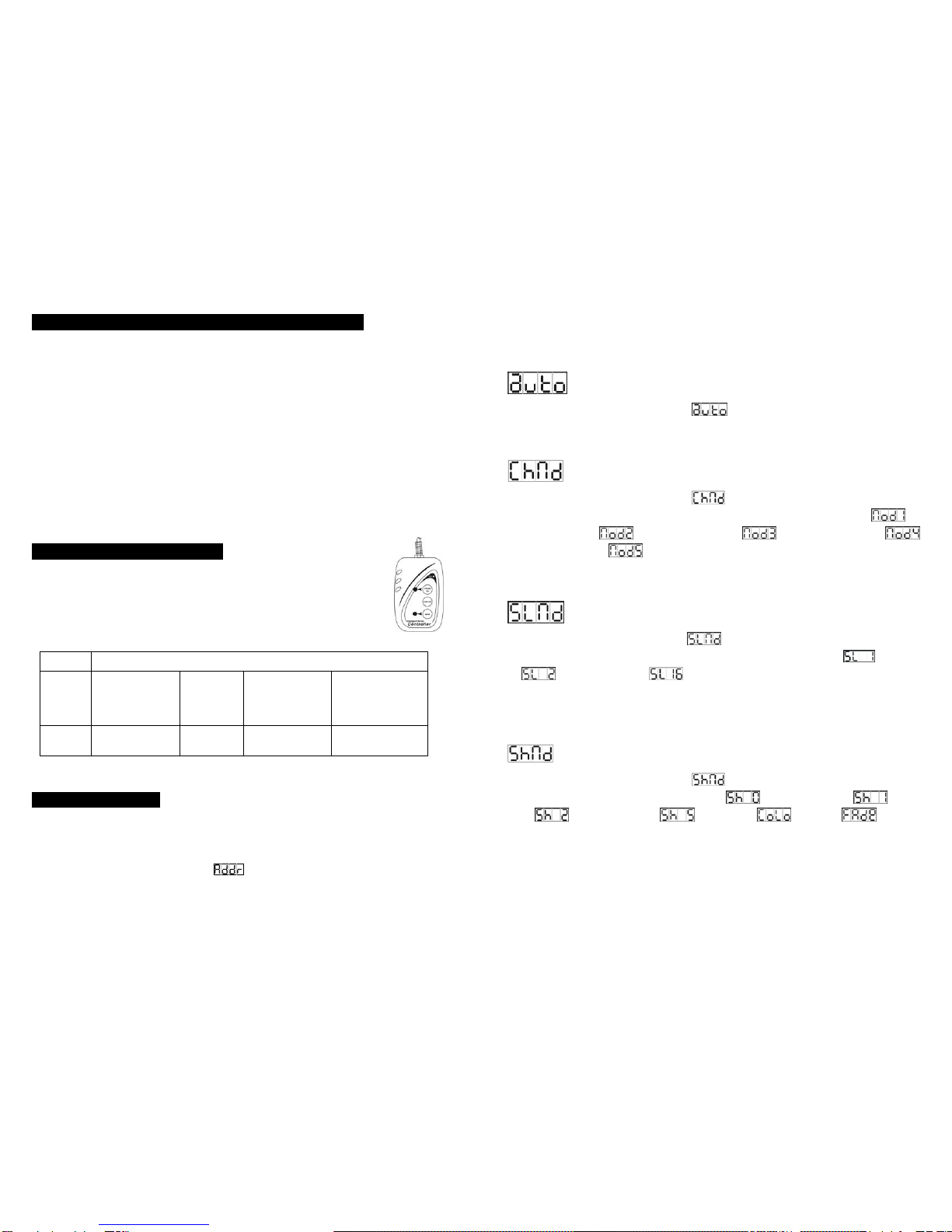
4.2. Easy Controller (by CA-8)
The easy remote control is used only in master/slave mode. By connecting to
the 1/4” microphone jack of the first unit, you will find that the remote controller
on the first unit will control all the other units for Stand by, Function and Mode
selection
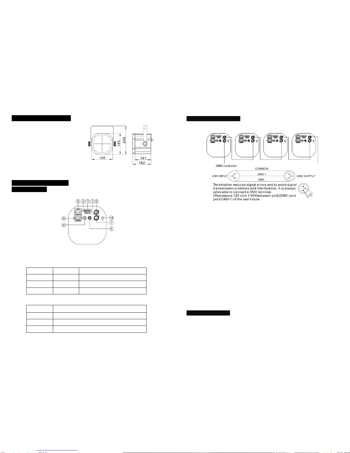
4.3 DMX Controller
Use universal DMX controller to control the units, you have to set DMX address from 1 to
512 channel so that the units can receive DMX signal.
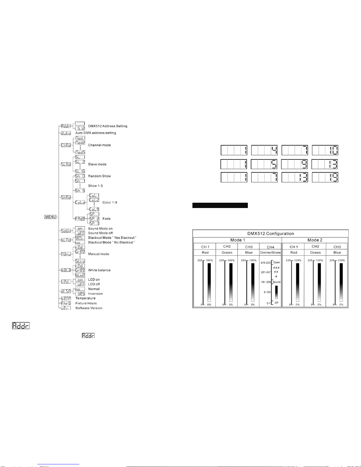
Press the MENU button up to when the is showing on the display. Pressing ENTER
button and the display will blink. Use DOWN and UP button to change the DMX512 address.
Once the address has been selected, press and keep ENTER button pressed up to when
Blackout Blackout the unit
Function 1. Strobe in white
2. Strobe in color
3. Sound Strobe
Select
color 1-9
Select
show 1-5
Fade Speed
1. Slow
2. Middle
3. Fast
Mode Sound/Strobe
(LED OFF) Chase
(LED ON) LED slow blinking LED fast blinking
8-
Once the address has been selected, press ENTER button to setup or automatically exit
menu mode without any change after one minute. Back to the previous functions without
any change press MENU button.
Auto DMX address setting
Press the MENU button up to when the is blinking on the display. Pressing ENTER
button and the DMX address of the fixture can be set automatically by built-in program. To go
back to the functions press the MENU button again.
Channel Mode
Press the MENU button up to when the is shown on the display. Pressing ENTER
button and the display will blink. Use DOWN and UP button to select the (4
channels mode) or (3 channels mode) or (6 channels mode) or
(4 channels mode) or (4 channels mode) mode. Once the mode has been selected,
press the ENTER button to setup or automatically exit menu mode without any change after
one minute. To go back to the functions without any change press the MENU button.
Slave Mode
Press the MENU button up to when the is showing on the display. Pressing ENTER
button and the display will blink. Use DOWN and UP button to select the (normal)
or (slave 2) or …or (16 light show) mode. Once the mode has been
selected, press the ENTER button to setup or automatically return to the main functions
without any change after one minute. To go back to the functions without any change press
the MENU button again.
Show Mode
Press the MENU button up to when the is shown on the display. Pressing ENTER
button, Use DOWN and UP button to select the (Random show) or (show
1) or (Show 2) or … or (show 5) or (color) or (fade), if
you select the color or fade mode, press ENTER button to confirm, and use DOWN and UP
button to select color 1-9 or fade speed (speed 1: slow, speed 2: middle, speed 3: fast).
Once select, press ENTER button to setup or automatically exit menu mode without any
change after one minute. To go back to the last function without any change press the
MENU button.