Addspace 041 5500 Series User manual

Assembly Instructions -Please keep for future reference
Width - 116cm
Sideboard
Important - Please read these instructions fully before starting assembly
If you need help or have damaged or missing parts, call the Customer Helpline: 01709 534123
Please turn to back page for important information when contacting Customer Helpline.
Dimensions
Depth - 39cm
Height - 73cm
Rev A - 31.03.15
041 xx 5500

Important - Please read these instructions fully before starting assembly
Safety and Care Advice
Check you have all the
components and tools listed on
pages 2 and 4.
Remove all fittings from the
plastic bags and seperate them
into their groups.
Keep children and animals
away from the work area, small
parts could choke if swallowed.
Make sure you have enough
space to layout the parts before
starting.
Do not stand or put weight on
the product, this could cause
damage.
Assemble the item as close
to its final position (in the same
room) as possible.
Assemble on a soft level
surface to avoid damaging the
unit or your floor.
Parts of the assembly will be
easier with 2 people.
We do not
recommend the
use of power
drill/drivers for
inserting screws,
as this could damage the unit.
Only use hand screwdrivers.
Care and maintenance
Always lift furniture when
moving it (do not drag)
otherwise the joints may be
damaged.
From time to time check that
there are no loose screws on
this unit.
This product should not be
discarded with household
waste. Take to your local
authority waste disposal centre.
1
Dust surfaces with a soft, dry,
lint free cloth.
More stubborn marks can be
removed using a damp
(not wet) cloth. Wipe the
surface dry immediately
using a soft lint free cloth.
Do not use detergants, abrasive
cleaning products or cleaning
products that contain ammonia,
solvents or silicone as these
may damage the surface finish.
To protect the furniture,
position the furniture out of
direct sunlight and away from
direct heat sources such as
radiators and fires.
Do not place the furniture in
excessively dry and humid
conditions.
Do not place hot or cold
objects on the surface, always
use protective mats to avoid
marking the furnture.
Clean spills up immediately
Dispose of all packaging
carefully and responsibly
when assembly complete.
Do Not dispose of packaging
until assembly complete.
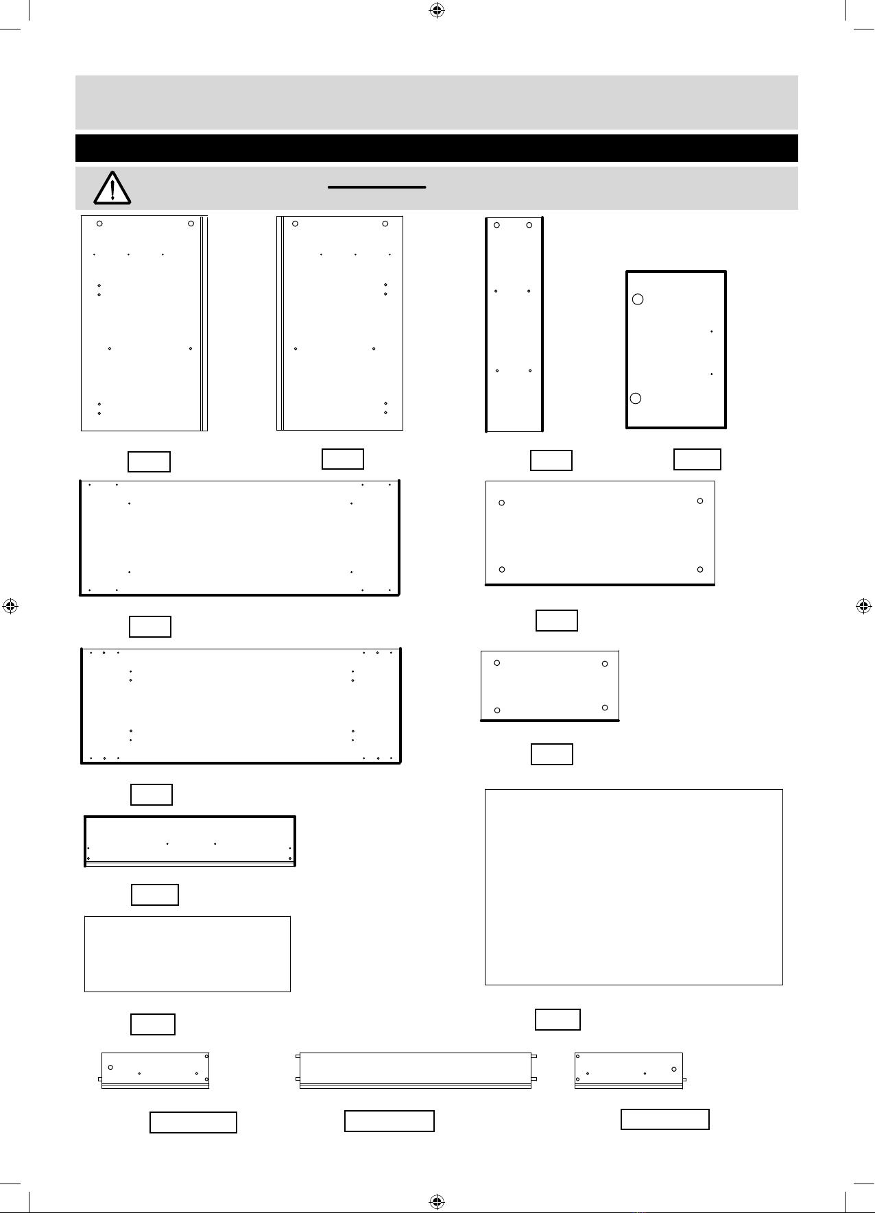
Please check you have all the panels listed below
Components -Panels
Left hand division (65x35cm) Right hand division (65x35cm)
Code - Code -
2
Important - Thick lines indicate finished edges
7498 7499
Shelf x 4 (35x17cm)
Backpanel (78.8x65cm)
Code - 7506
Drawer front (77.2x15.7cm)
Code - 7505
Top (116x39cm)
Drawer bottom (75.6x29.8cm)
Code -
7019
7500
7504
Code -
Code -
Left drawer side (30x10cm)
Code -
Drawer back (74.5x10cm)
Code -
Right drawer side (30x10cm)
Code -
622xx7002 624xx7007 623xx7002
Door x 2 (48.4x38.4cm)
Code - 7010
Bottom (116x39cm)
7501
Code -
Rail x 4 (65x18.8cm)
Code - 7502
Shelf (77.8x33cm)
7503
Code -

3
Components -Exploded View
Important - Thick lines indicate finished edges
7500
7504
7502
7502
7498
7398
7010
622xx7002
624xx7007
623xx7002
7019
7505
7502
7504
7504
7503
7499
7502
7501
7010
7504
7506

70 80 90 100 110 120
0 10 20 30 40 50 60
mm
130 140 150 160 170
Ruler - Use this ruler to help correctly identify the screws
Please check you have all the fittings listed below
Components-Fittings
Note: The quantities below are the correct amount to complete the assembly, In some case more fittings
may be supplied than are required.
Tools required
If you have damaged or missing components, call the
Customer Helpline: 01709 534123 Please turn to back page
for important information when contacting Customer Helpline.
4
Cross headed screwdriver
(small & large )
Small Hammer
Tape Measure
Eye protection
(when using a
hammer)
Large cam x 32 - Code 760001103 Metal dowel x 34 - Code 760003004 Small cam x 2 - Code 760003005
12mm screw x 14 - Code 690001008 Runner x 2 - Code 760001040
9mm bolt x 2 - Code 690001078
A B C
D E H
IJ
L
45mm screw x 12 - Code 690001075
MN
Wooden dowel x 8
Code 770001006
O
Fully cranked 26mm
hinge x 4
Code 652001120
P
Hingeplate x 4
Code 653006000
Bradawl
K
Handle x 3
Code 644396000
22mm screw x 16- Code 690001018
Square foot x 5
Code 720396000
Tube of glue x 1 - Code 680001037
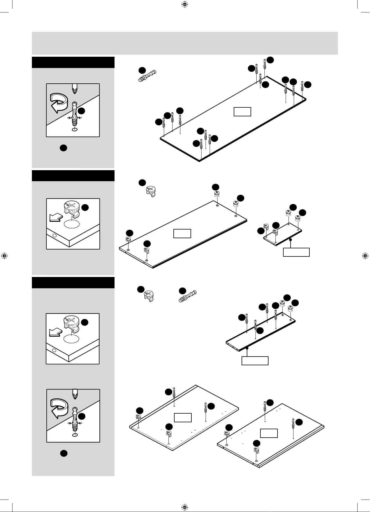
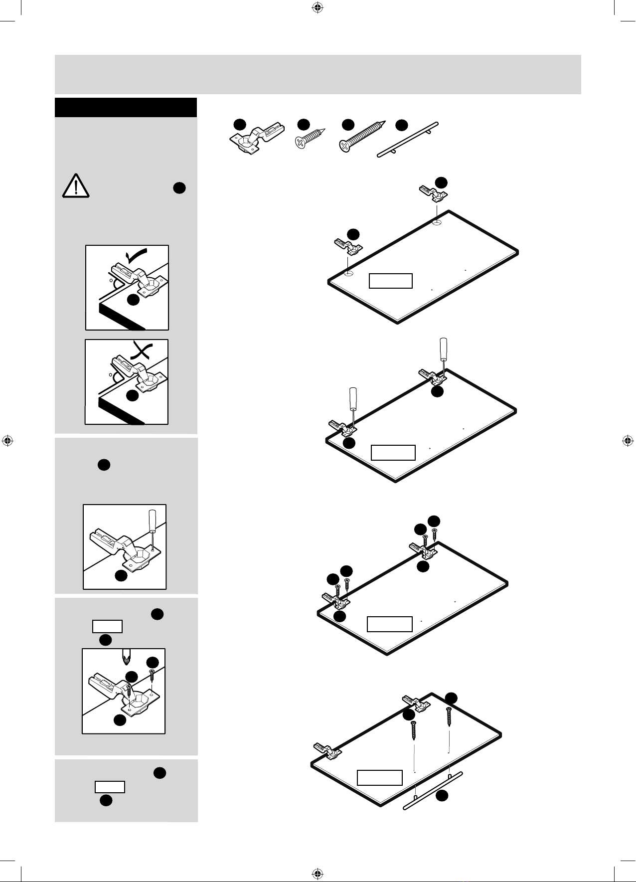
Step 1
Assembly Instructions
5
Fittings you will need for this step:
A
B
B
B
(x12)
Note: Insert metal
dowels as far as
shown by arrows.
Do not over tighten.
B
Fittings you will need for this step:
A
(x20)
Note: Ensure cam
arrow points towards
the edge with hole.
A
Fittings you will need for this step:
A
(x12)
Fitting dowels to top
panel
Fitting cams to
shelves
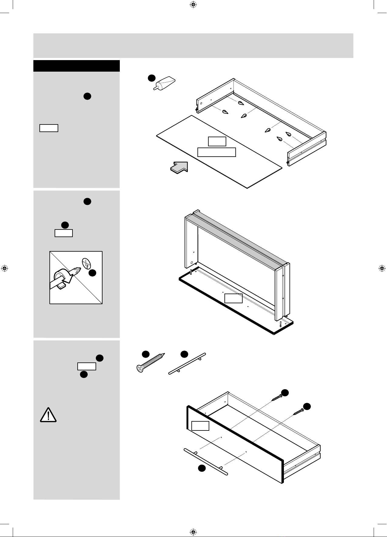
Step 2
Step 3
Fitting cams and
dowels to left, right
divisions and rails
Large
Large
7500
B
7504 x4
Note: Ensure cam
arrow points towards
the edge with hole.
A
B
B
A
A
A
7503
Note: Insert metal
dowels as far as
shown by arrows.
Do not over tighten.
B
B
B
(x20)
A
A A
A
B
B
B
B
7498
7499
B
B
B
B
B
B
B
B
B
A
A
A
A
A
A
7502 x4
B
B
B

B
7499
7498
Step 4
Assembly Instructions
6
Fittings you will need for this step:
Fittings you will need for this step:
Fittings you will need for this step:
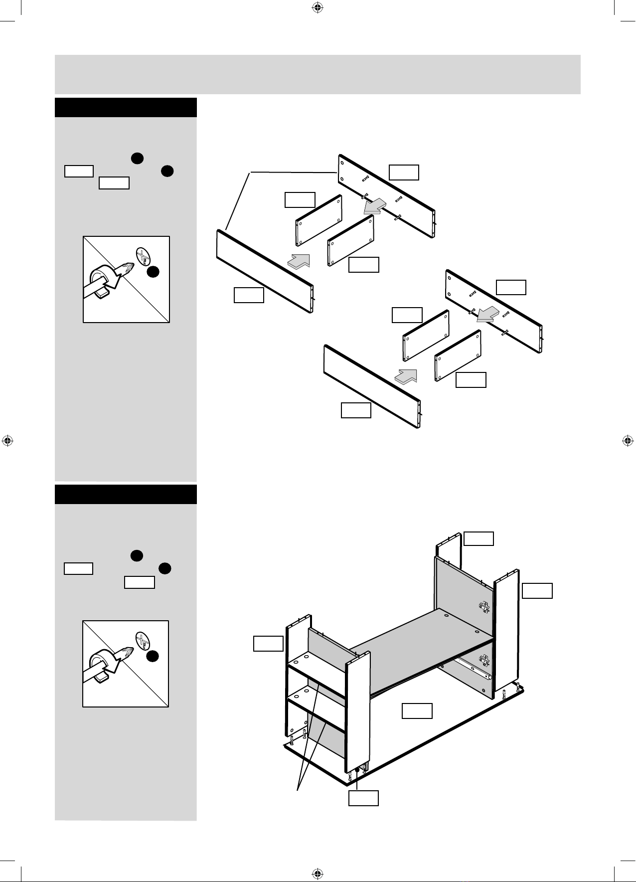
Fitting hingeplates
to left hand division
Step 5
Step 6
Fitting wooden
dowels to left, right
hand divisions
Notch in Hingeplate points
towards edge.
P
P
P
P
(x2)
P
Notch in Hingeplate points
towards edge.
P
Fitting hingeplates
to right hand division
P
(x2)
P
N
(x8)
N
N N
N
Use a hammer to
knock in wooden dowels
into inner holes.
N
N
7502 x4
N
7499
7498
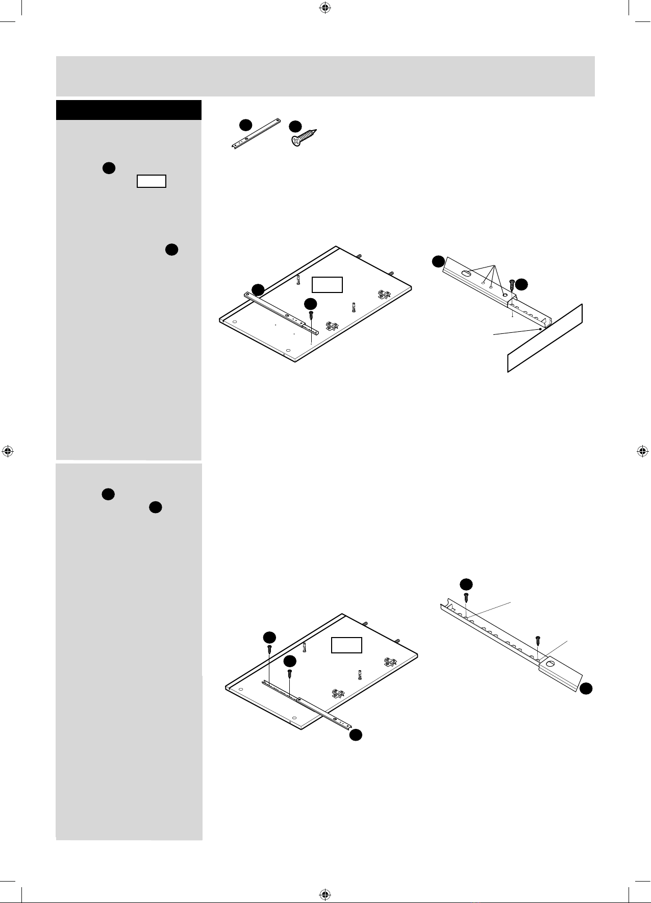
7498
a:Align the drawer
runner with the
edge of panel ,
the 2nd hole from
the front will then line up
with a pre-drilled hole,
secure the runner to the
panel using screws .
7
2ND
Middle
Fittings you will need for this step:
(x1)
D
Attaching runners
H
b:Slide the drawer
runner forward to
secure 2 screws .
The 2nd to last and
middle hole in the
runner will line up with
the pre-drilled holes in
the panel.
D
H
D
H
(x3)
H
D
Assembly Instructions
Step 7
a:
b:
7498
H
D
H
Note:
Please note
runner sits
flush with
edge.
Note:
Ensure these
holes are
positioned as shown.
D
H
D
D
7498
7499
8
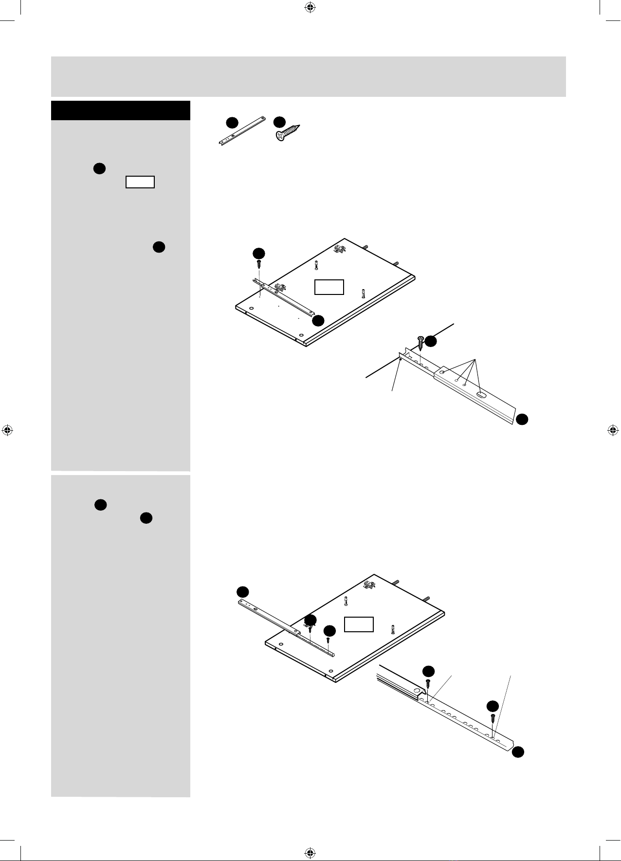
Fittings you will need for this step:
(x1)
D
H
(x3)
Note:
Ensure these
holes are
positioned as
shown.
Assembly Instructions
Step 8
a: Align the drawer
runner with the
edge of panel ,
the 2nd hole from
the front will then line up
with a pre-drilled hole,
secure the runner to the
panel using screws .
D
Attaching runners
H
b: Slide the drawer
runner forward to
secure 2 screws .
The 2nd to last and
middle hole in the runner
will line up with the
pre-drilled holes in the
panel.
D
H
D
H
2ND
Middle
D
H
H
D
D
H
D
a:
b:
7499
Note:
Please note
runner sits
flush with
edge.
D
7499
9
Fittings you will need for this step:
Assembly Instructions
Step 9
Attach hinges and
handles to doors
a: Insert hinges
into holes, ensure
the hinge is straight
(90 degree angle).
b: Before securing the
hinges , we recommend
you pre - mark the doors
using a bradawl.
Important:
(x4)
J
M
(x2)
(x8)
D
(x4)
O
O
O
90
O
98
O
O
O
7010x2
O
Bradawl
O
D
D
c: Secure hinges to
doors using
screws .
O
7010
D
d: Secure handle to
doors using
screws .
J
M
7010
O
7010x2
J
7010x2
O
O
O
7010x2
a:
b:
c:
d:
D
D
D
D
M
M

a: Insert dowels into
drawer fronts .
Note: Insert metal
dowels as far as
shown by arrows.
Do not over tighten.
10
Fittings you will need for this step:
(x2)
Drawer assembly
B
B
C
(x2)
Step 10
c: Insert wooden dowels
in drawer back
into holes in
left
right hand
drawer sides.
B
b: Insert small cams
into left
and right
drawer sides.
Note: Ensure cam arrow
points towards the edge
with hole.
C
C
B
B
Fittings you will need for this step:
Small
C
C
a:
b:
c:
Left hand side
Right hand side
Left hand side
Right hand side
Drawer Back
Continued on next page.
7505
7505
622xx7002
624xx7007
623xx7002
622xx7002
623xx7002
622xx7002
623xx7002
623xx7002
624xx7007
622xx7002
Assembly Instructions
J
e:Insert cams already
inserted in left and right
drawer sides onto
dowels in drawer
front .
11
Fittings you will need for this step:
(x2)
Drawer assembly
Continued...
C
J
(x1)
Assembly Instructions
Step 10 - Continued
d: Using glue put a
few drops into grooves in
drawer sides and back.
Slide drawer bottom
into grooves in
left,right drawer sides
and drawer back.
Ensure foil on the
drawer bottom is facing
upwards.
B
Turn cam 180 degrees
to lock
f: Secure handles to
drawer front
using screws .
C
J
M
d:
e:
f:
7019
7505
7019
7505
7505
FOIL FACE
Fittings you will need for this step:
E
(x1)
E
7505
Important:
Please allow 40 minutes
for the glue to set before
using the drawer.
M
M
M

Locate cams in shelf
onto dowels in
left and right
hand divisions.
Then lock.
B
A
Turn cam 180 degrees
to lock
A
12
Attach left and right
hand divisions to
shelf
Assembly Instructions
Step 11
Attach left and right
hand divisions to top
panel
Step 12
7503
7498 7499
Locate cams in left
and right
hand divisions onto
dowels in top .
Then lock.
B
A
Turn cam 180 degrees
to lock
A
7498 7499
7499
7503
7498
7500
7499
7498
7500
13
Locate shelves to
rails
Assembly Instructions
Step 13
Attach rails to top
panel
Step 14
Turn cam 180 degrees
to lock
A
7504
7502
Locate cams in panels
onto dowels
in top panel .
Then lock.
B
A
7502
7500
7504
7502
7504
7502
7504
7502
Turn cam 180 degrees
to lock
A
Locate cams in shelves
onto dowels
in rails .
Then lock.
B
A
7504
7502
7502
4755
6086
7502
7502
7502
7500
Ensure cam holes to
top.
Finished edge

14
Assembly Instructions
Step 15
Locate backpanels
into grooves in left
and right hand end
divisions
Step 16
Locate backpanel
into grooves in left hand
and right hand
slide the
backpanel all the
way down to the top
panel.
7506
7499
7498
7506
4755
6086
7506
4755
6086
7502
7499
7498
L
Locate wooden dowels
already inserted in
divisions and
and rails into holes
in bottom panel .
Now locate screw
through holes in bottom
panel and screw
into holes in divisions
. , and rails
.
N
7498
7501
L
7501
7498
L
L
7499
7499
(x12)
L
Fittings you will need for this step:
Attach bottom to rails
and divisions
7501
7502
7502
7502
7499
7498
L
L
L
L
L L
L
L
L
L
7502
7502
Raw face
FOIL FACE
15
Assembly Instructions
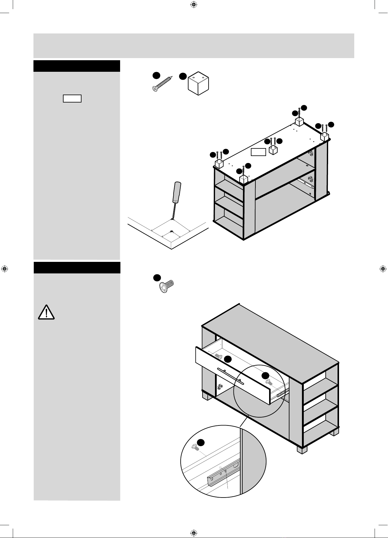
Step 17
Step 18
Attach feet
M
(x10)
K
(x5)
Bradawl
15mm
15mm
38mm
38mm
To locate feet to the
bottom you will
need to mark position
with a bradawl 15mm
and 38mm in as shown,
then screw the foot into
place.
Repeat in each corner.
Attach the 5th foot
centrally.
7501
Fittings you will need for this step:
PLEASE NOTE: BOTTOM PANEL
EDGED IN SILVER.
4755
6086
7501
M
M
M
M
M
M
M
M
M
M
Lift unit onto its feet
then locate drawer
(x2)
I
For this step we
recommend you follow
the helpful hints page
on page 16.
Fittings you will need for this step:
2nd HOLE
I
Warning:
2 people to lift.
Lift with care.
I
I

Assembly Instructions
16
Step 18 continued
a: Pull sliding part of
drawer runners out
so they are fully
extended.
Locate drawers helpful
hints
H
b: Locate drawer onto
runners.
c: Locate screwdriver
into second threaded
hole in drawer runner .
d: Keeping screwdriver
in place push the drawer
in until the screwdriver
pushes against the
panel.
Remove the screwdriver.
e/f: Pull drawer out slowly
and line the front hole in the
drawer side with the 2nd
threaded hole in runner .
Holding runner and
drawer side together
insert bolts through the
drawer side and
into threaded hole in
runner .
I
J
Now repeat these
steps for the other
side of the drawer.
J
D
EF
AB
C
2nd Hole
H
2nd Hole
J
L
L
L
L
L
I
H
H
H
H
H
H

Assembly Instructions
Step 19
17
a: With help, slot door
hinges onto hinge
plates .
Ensure screw on hinge
slides into the slot
on hingeplate .
See Diagrams 1,2 and 3.
Hanging doors
O
b: Tighten screw shown
to lock hinges in
position.
Repeat a and b for
opposite door.
See ‘Hinge adjustment’
in step 20 if the doors
need adjusting.
a:
b:
B
B
B
O
P
O
O
P
P
P
O
P
Underside view
Ensure the underside of screw
B slides into slot on hingeplate.
Hinge correctly attached to
hingeplate.
Hinge incorrectly attached to
hingeplate.
Diagram 1
Diagram 2
Diagram 3
7010
O
P

Assembly Instructions
Step 20
18
a: To move doors up
or down: loosen screws
shown and move doors
to suit.
Re-tighten screws.
Hinge adjustment
b: To move doors in or
out: loosen screw
shown and move doors
to suit.
Re-tighten screws.
a:
O
P
b:
O
P
O
P
c:
c: To move doors left
or right: loosen or
tighten screw as shown
Be careful not to fully
unscrew.
Congratulations!
Your unit is complete

19
If you need help or have damaged or missing parts, call the Customer Helpline: 01709 534123
Please have the following information: Unit Description, Product Code, Product Colour,
Place of Purchase, Catalogue Ref. No., Item Code, and have the assembly instructions close
to hand.
You can also e-mail your requests to us at: customer.helpdesk@addspacefl.co.uk
Simply contact us on CUSTOMER HELPLINE : 01709 534123 Between 8am - 4.30pm
Monday to Thursday and 8am - 2.30p.m friday. Your statutory rights are not affected.
Alternatively Write to us at: Customer Service Department, Addspace Furniture Limited,
Braithwell Way, Hellaby Industrial Estate, Hellaby, Rotherham, South Yorkshire, S66 8QY.
We do have an answer machine should you contact us out of office hours, so in addition to
the above information could you leave your name, address, daytime telephone number and
the nature of your call on the answerphone. All calls will be actioned asap.
Important Information
Table of contents
Other Addspace Indoor Furnishing manuals

Addspace
Addspace 051 0510 Series User manual

Addspace
Addspace 033 7500 Series User manual

Addspace
Addspace 041 5527 Series User manual

Addspace
Addspace 052 7921 Series User manual

Addspace
Addspace OFW00124 User manual

Addspace
Addspace 01709 534123 User manual

Addspace
Addspace Helsinki OA580 User manual

Addspace
Addspace 011 7027 Series User manual

Addspace
Addspace 482/4536 User manual

Addspace
Addspace 3 Door Robe 001 6026 Series User manual


