Addspace 3 Door Robe 001 6026 Series User manual
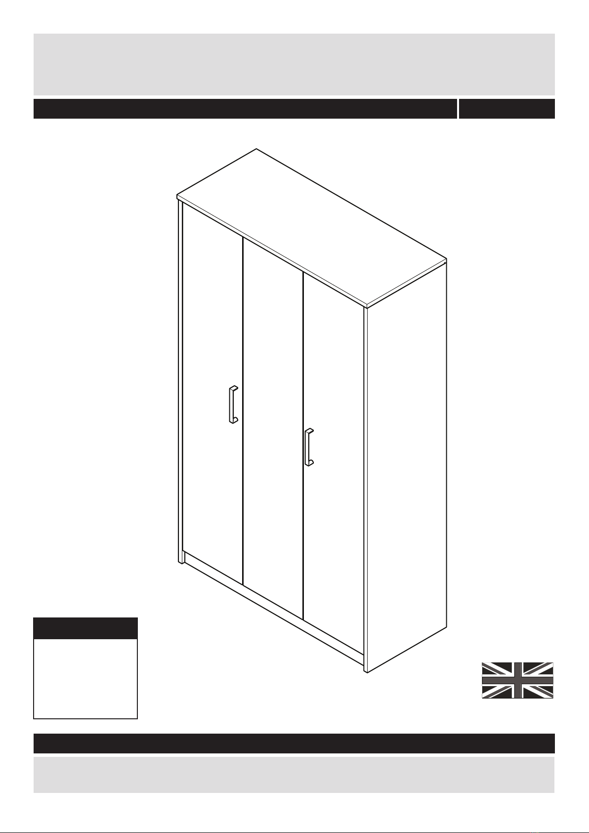
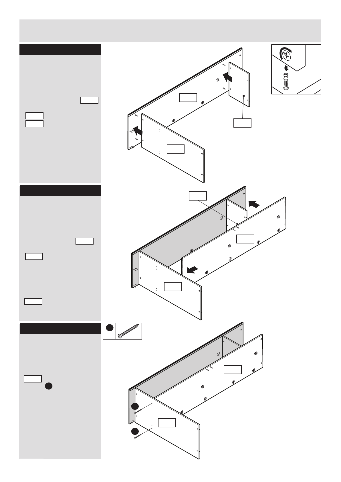
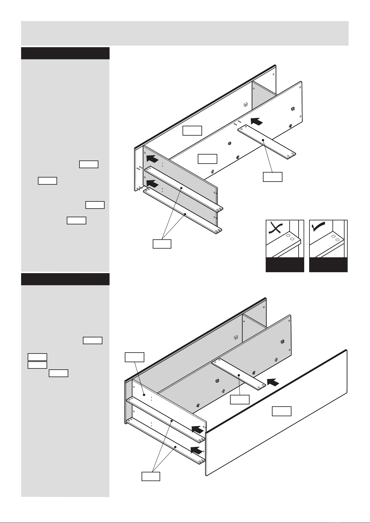
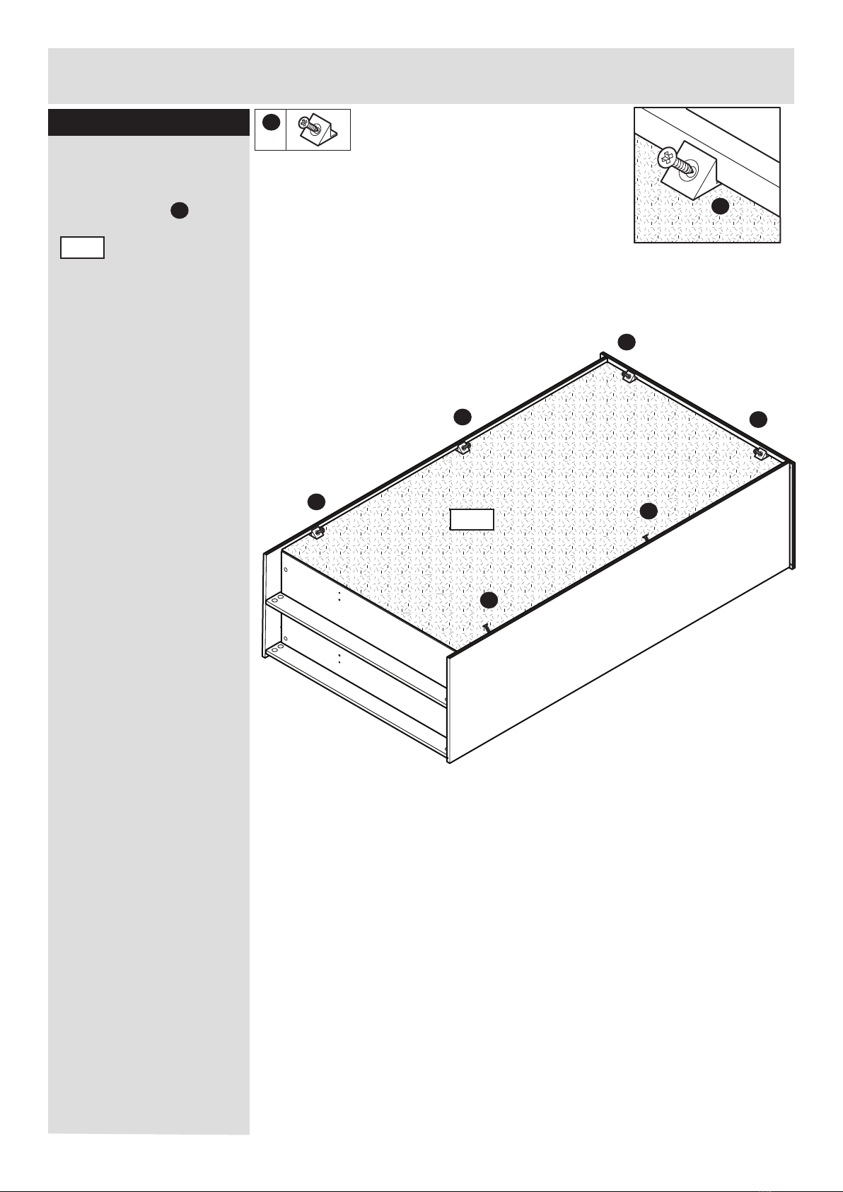
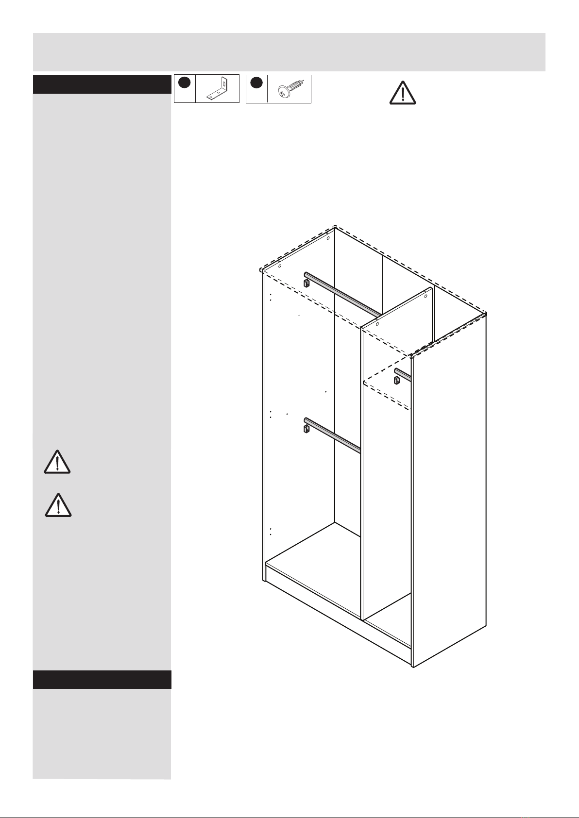
Assembly Instructions - Please keep for future reference
Width - 119.2cm
3 Door Robe
Important - Please read these instructions fully before starting assembly
If you need help or have damaged or missing parts, call the Customer Helpline: 01709 534123
Please turn to back page for important information when contacting Customer Helpline.
Dimensions
Depth - 49.8cm
Height - 200.0cm
Rev C - 07/02/17
001 xx 6026
MADE IN
GREAT BRITAIN

Important - Please read these instructions fully before starting assembly
Safety and Care Advice
Check you have all the
components and tools listed on
pages 2 and 3.
Remove all fittings from the
plastic bags and seperate them
into their groups.
Keep children and animals
away from the work area, small
parts could choke if swallowed.
Make sure you have enough
space to layout the parts before
starting.
Do not stand or put weight on
the product, this could cause
damage.
Assemble the item as close
to its final position (in the same
room) as possible.
Assemble on a soft level
surface to avoid damaging the
unit or your floor.
Parts of the assembly will be
easier with 2 people.
We do not
recommend the
use of power
drill/drivers for
inserting screws,
as this could damage the unit.
Only use hand screwdrivers.
Care and maintenance
Always lift furniture when
moving it (do not drag)
otherwise the joints may be
damaged.
From time to time check that
there are no loose screws on
this unit.
This product should not be
discarded with household
waste. Take to your local
authority waste disposal centre.
1
Dust surfaces with a soft, dry,
lint free cloth.
More stubborn marks can be
removed using a damp
(not wet) cloth. Wipe the
surface dry immediately
using a soft lint free cloth.
Do not use detergents, abrasive
cleaning products or cleaning
products that contain ammonia,
solvents or silicone as these
may damage the surface finish.
To protect the furniture,
position the furniture out of
direct sunlight and away from
direct heat sources such as
radiators and fires.
Do not place the furniture in
excessively dry and humid
conditions.
Do not place hot or cold
objects on the surface, always
use protective mats to avoid
marking the furniture.
Clean spills up immediately
Dispose of all packaging
carefully and responsibly
when assembly complete.
Do Not dispose of packaging
until assembly complete.

Please check you have all the panels listed below
Components -Panels
2
Important - Thick lines indicate finished edges
Top (119.2x49.8cm)
9869
Left End Panel
(197.8x49.6cm)
9865
Right End Panel
(197.8x49.6cm)
9871 Divider
(188.5x46.4cm)
9872
Bottom (114.6x46.4cm)9870
Plinth x 2 (114.6x7.6cm)9860
Back Rail (75.3x12.4cm)9334
Small Shelf
(37.8x46.4cm)
9875
9876
Back Panel (Folded)
(190.3x115.5m)
Door x 2
(189.4x38.9cm)
0049
Central Door
(189.4x35.7cm)
9874
Large Shelf
(75.3x44.8cm)
9884
Hanging rail x 2
(74.8cm Long)
740006009
Hanging rail
(37.3cm Long)
740006011
Top Rail (62.4x6.0cm)
7194
Top Rail (30.1x6.0cm)
7200

3
70 80 90 100 110 120
010 20 30 40 50 60
mm
130 140 150 160 170
Ruler - Use this ruler to help correctly identify the screws
Please check you have all the fittings listed below
Components - Fittings
Note: The quantities below are the correct amount to complete the assembly, In some case more
fittings may be supplied than are required.
Tools required
If you have damaged or missing components, call the
Customer Helpline: 01709 534 123 Please turn to back page
for important information when contacting Customer Helpline.
Cross headed screwdriver
(medium & large )
Small Hammer
Tape Measure
Eye protection
(when using a
hammer)
Large cam x 26
Code 760001103
Metal dowel x 26
Code 760003004
ABC
E
DF
I
Panel pin x 12
Code 760001012
Panel pin guide x 1
Code 684004501
G
20mm bolt x 4
Code 700002006
H
J
Support bracket x 2
Code 760001901
K
Hingeplate x 12
Code 653006000
Hanging supports x 6
Code 680006003
L
M
12mm screw x 36
Code 690001008
NP
12mm screw x 4
Code 690001099
Wooden dowel x 2
Code 770001006
Assembly Screw x 2
Code 690001075
Handle x 2
Code 644003512
Panel Holder x 6
Code 680003505
Q
25mm Screw x 4
Code 690001021
Shelf Pin x 4
Code 760001137
R
Fully cranked 26mm
hinge x 12
Code 652001120
Drill

Exploded View
4
7194
7200
0049
0049
9874
9875
9876
9884
9865
9872
9871
9870
9860
9334
9869

Step 1
Assembly Instructions
5
B
x6
B
Fitting dowels to top
panel.
B
A
Step 3
A
AAA
A
A
A
A
Fitting cams into the
bottom panel.
Insert 6 metal dowels
into the top panel 9869
Insert 4 metal cams
into bottom panel .
9870
Note: Tighten metal
dowels up fully against
the panel.
Do not over-tighten.
A
x4
A
A
x12
Step 4
Fitting cams into the
back rail and plinths
panels.
Insert 4 metal cams
into the back rail .
9334
A
B
BB
B
B
B
9869
9870
9860 x2
AAAA
9334
Insert 4 metal cams
into plinth panel &
on the remaining plinth.
9860
A
Step 2
9869
7194
7200
Q
Q
Q
Q
x4
Connect the top rail
to the top panel.
Using 4 screws secure
the top rails and
to the top panel
.
9869
7194
7200
Q
Q

Assembly Instructions
6
Step 5
Attach hinges to the
3 doors and handles
to 2 doors.
A: Insert hinges
into holes, ensure
the hinge is straight
(90 degree angle).
B: Before securing the
hinges , we recommend
you pre - mark the doors
using a bradawl.
I
I
Bradawl
C: Secure hinges to
doors using screws .
Repeat on the remaining
doors.
I
F
I
x12
F
x24
0049
0049
0049
0049
F
F
F
F
F
F
F
F
A
B
C
D
90
Correct
98
Incorrect
I
I
I
I
D:
Fit 2 bolts through
the pre-drilled holes in
the door
and connect to the handle
.
D
D
D
G
0049
D
x4
G
x2
G
Repeat on the remaining
door.
0049
)FÖTHESEÖFRONTSÖHAVEÖAÖ
GLOSSÖFINISHÖTHEYÖMAYÖ
REQUIREÖAÖPROTECTIVEÖFILM
TOÖBEÖREMOVEDÖ
0LEASEÖPEELÖOFFÖBEFOREÖ
ATTACHINGÖHANDLES

Assembly Instructions
7
Step 6
K
x4
F
x4
P
x2
Insert 4 hinge plates
into the left end panel
.
Insert 4 screws through
the holes in the hanging
rail supports .
Note: A bradawl may be
required when attaching
the hanging rail support
to create the lower hole.
F
P
9865
K
K
K
K
F
P
F
P
9865
Fitting hanging rail
support & hingeplates
to left end.
Step 7
Fitting cams & dowels
to the left end panel.
B
x8
A
x2
Insert 8 metal dowels
and 2 cams into
left end panel
BA
9865
B
B
BBB
BB
A
9865
A
K

Assembly Instructions
8
A
x4
Step 10
Fitting cams the
shelf panels.
Insert 4 cams into the
shelf panel
A
9875
A
A
A
A
9875
Fitting hanging rail
support & hingeplates
to right end.
Insert 4 hinge plates
into the right end panel
.
Insert 2 screws through
the holes in the hanging
rail supports .
Note: A bradawl may be
required when attaching
the hanging rail support
to create the lower hole.
F
P
9871
Step 8
K
K
K
K
x4
F
x2
P
x1
F
P
9871
B
x8
A
x2
Step 9
B
B
B
B
BB
BB
Fitting cams & dowels
to the right end panel.
Insert 8 metal dowels
and 2 cams into
right end panel
BA
9871
9871
A
A
K
K

Assembly Instructions
9
Step 11
Step 12
Step 13
K
K
K
K
F
x4
P
x2
K
x4
B
x2
B
B
x2
A
x2
B
F
x2
P
x1
J
J
J
x2
9872
9872
9872
Attach haing rail
support and cams to
the divider panel.
Insert 2 metal cams
into the divider panel
.
Secure the hanging rail
support bracket with 2
screws .
9872
A
Attach dowels and
hinge plates.
Insert 2 metal dowels
and 4 hingeplates
into the divider panel and
insert 2 wooden dowels
into the central holes
of the divider panel
.
F
P
K
B
TURN PANEL OVER
Attach hanging rail
support and metal
dowels.
Secure the hanging rail
support bracket with 2
screws .
Insert 2 metal dowels
9872
F
P
J
B
B
P
A
A
F
P
F
F
P
B
Use the packaging
your unit came in to
ensure that the fittings
in the reverse face do
not damage the floor.

Assembly Instructions
10
Step 14
Connect the right end
panel to the bottom,
and small shelf.
Connect the dowels in
the right end panel
to the cams in the bottom
and the small shelf
.
Turn cams 180 degrees
clockwise to lock.
9871
9870
9875
Step 15
Step 16
Connect the divider
panel to the small shelf
and the bottom panel.
Connect the dowels in
the divider panel
to the cams in the shelf
.
Connect the wooden
dowels in the bottom of
the divider to the central
holes in the bottom panel
.
Secure the bottom
panel to the divider
panels.
(x2)
M
Secure the bottom panel
in place with 2
screws in the outer
holes.
M
9875
9875
9872
M
M
9870
9872
9875
9870
9871
9870
9872
9870
9870

Assembly Instructions
11
9860
9870
9860
Step 17
Connect the right end
panel to the plinths
and back rail. Connect
the large shelf to the
divider.
Connect the dowels in
the divider panel
to the cams in the back
rail .
Connect the dowels in
the right end panel
to the cams in both of the
plinth panels .
9872
9334
9871
9860
Step 18
Connect the left end
panel to the bottom,
large shelf, rail and
plinth panels.
Connect the dowels in
the left end panel
to the cams in the bottom
, the back rail
and the plinths
panels .
9865
9870
9334
9860
Ensure plinth is
not overhanging.
Ensure plinth sits
flush.
9334
9865
9872
9871
9334
We recommend that an
additional person is used
to support the plinth
panels during this stage
and the next stage.

Assembly Instructions
12
Step 20
Step 19
Slide the back panel into
the grooves in the left and
right hand end panels.
Push the back panel into
the groove in the top
panel.
Slide back panel into
the grooves.
Connect the dowels in the
top panel to the
cams in the left end
, divider and
the right end panel .
Connect the top panel
to the divider and the
end panels.
2 people will be
required to insert the
back panel.
9869
9872
9865
9871
9876
9871
9872
9869
9865
Tape on
this side

Fixing back panel in
place.
Use the panel pin guide
when locating the panel
pins . This will hold the
panel pins vertical and
ensure the correct
distance from the edge.
Assembly Instructions
13
8588
8589
9143
Step 22
9876
N
N
N
x12
E
E
x1
Step 21
DIAG 1 DIAG 2 DIAG 3
XX
XX
XX
YY
YY
YY
YY
XX
XX
YY
YY
XX
XX
YY
YY
Measure to
external corners
Squaring up the unit.
IMPORTANT!
Before securing the back
it is necessary to square
up the unit. Make sure
that the back panel is
still sat in the grooves.
You can do this by
measuring between
XX - XX and YY - YY
ensuring these are the
same (DIAG 1).
If they are not (DIAG 2)
Apply slight pressure as
indicated (DIAG 3) until
they are the same.
Ensure a tape
measure is used
to square unit up.
8588
8589
9143
XX

Assembly Instructions
14
8588
8589
9143
x6
Step 23
Add stability blocks.
Slide the thin point of the
stability blocks
between the back panel
and the grooves.
Once inserted fully,
tighten the screws in the
stability blocks.
L
L
L
L
L
L
L
L
L
9876
9876

Assembly Instructions
15
Step 24
Step 25
We recommend that this
unit is fixed to a suitable
wall to prevent possible
overbalancing. We have
included a fixing bracket
for this. No fixing screws
are provided as they will
need to suit the wall
type, and the length of
screw will depend on
the distance from the
back of the unit to the
wall. Please ensure
fixings used are
appropriate to your wall
type. Locate the bracket
to the top panel or to the
end panel as close to
top as possible. We do
not specify exact
location for the bracket,
this is left to the
customer’s discretion.
Fixing to wall
Please take care when
drilling into the wall,
avoiding any pipes and
wires. Wear safety
goggles when drilling.
The use of residual
current device (RCD) is
recommended when
working with tools.If in
doubt consult a
qualified person.
Warning:
2 people to lift.
Lift with care.
With help move the
unit into position.
Warning:
Locate hanging rails
onto brackets already
attached. The hanging
rail just slots onto the
brackets.
Locate hanging rails
IMPORTANT!
This unit must be secured to the
wall prior to fitting the doors.
Failure to do this could make the unit
unstable and potentially dangerous
when the doors are opened.
H
x2
C
x4

Assembly Instructions
16
Step 26
The internal shelf is
optional and is not
required for unit stability.
If you wish to fit the
shelf, insert the 4 shelf
supports and seat the
shelf panel on top of the
supports.
Fixing the shelf panel
R
R
x4
R
R

Assembly Instructions
17
B
B
B
Underside view
Ensure the underside of screw
B slides into slot on hingeplate.
Hinge correctly attached to
hingeplate.
Hinge incorrectly attached to
hingeplate.
Diagram 1
Diagram 2
Diagram 3
Step 27
a: With help, slot door
hinges onto hinge plates.
Ensure screw on hinge
slides into the slot on
hingeplate.
See Diagrams 1, 2 and 3.
Hanging doors
b: Tighten screw shown
to lock hinges in
position.
See ‘Hinge adjustment’
page if the doors
need adjusting.
Repeat the process on
the remaining doors.
A
B
0049
0049 9874

Assembly Instructions
18
Step 28
a: To move doors up
or down: loosen screws
shown and move doors
to suit.
Re-tighten screws.
Hinge adjustment
b: To move doors in or
out: loosen screw
shown and move doors
to suit.
Re-tighten screws.
c: To move doors left
or right: loosen or
tighten screw as shown.
Be careful not to fully
unscrew.
A
B
C

Assembly Instructions
Congratulations! Your unit is complete.
Important Information
If you need help or have damaged or missing parts, call the Customer Helpline:
01709 534123 8am - 4.30pm (Monday toThursday)
8am - 2.30pm (Fridays)
Please have the following information to hand:
>> Unit Description
>> Product Code
>> Product Colour
>> Place of Purchase
>> Catalogue Ref. No.
>> Item Code
>> Assembly Instructions
You can also e-mail your requests to us at:
customer.helpdesk@addspacefl.co.uk
Alternatively, you can write to us at: Customer Service Department, Addspace Furniture Limited,
Braithwell Way, Hellaby Industrial Estate, Hellaby, Rotherham, South Yorkshire, S66 8QY.
We do have an answer machine should you contact us out of office hours, so in addition to
the above information could you leave your name, address, daytime telephone number and
the nature of your call on the answerphone. All calls will be actioned asap.
(by contacting the customer service line your statutory rights are not affected)
Table of contents
Other Addspace Indoor Furnishing manuals

Addspace
Addspace 052 7921 Series User manual

Addspace
Addspace 003 9500 Series User manual

Addspace
Addspace 01709 534123 User manual

Addspace
Addspace 041 5500 Series User manual

Addspace
Addspace 002 0581 Series User manual

Addspace
Addspace 051 0510 Series User manual

Addspace
Addspace 041 5527 Series User manual

Addspace
Addspace 482/4536 User manual

Addspace
Addspace 033 7500 Series User manual

Addspace
Addspace OFW00124 User manual